eove EOVE-70 User manual
1
102-035 Rev DG _ 13/09/2022 _ Apply from API39 Version
EOVE–70
SECRETION MANAGEMENT DEVICE
TECHNICAL MANUAL
EO-Display version

2
Current version: API39
PAGES
CHANGES AND MODIFICATIONS
71 / 79
Update of preventive maintenance schedule –Pump must be replaced when the counter
reaches 1000h
83-84
Preventive maintenance alarms

3
SUMMARY
1 Warnings........................................................................................................................................ 10
1.1 Warnings and safety rules..................................................................................................... 10
1.2 Responsibilities...................................................................................................................... 10
1.3 Maintenance and guarantee................................................................................................. 10
2 General information...................................................................................................................... 11
2.1 Technical description............................................................................................................. 11
2.2 The Technical data................................................................................................................. 15
2.3 Structure and operation........................................................................................................ 15
2.3.1 EOVE-70 SMD module structure ................................................................................... 15
2.3.2 EO-Display housing unit structure................................................................................. 16
2.3.3 Operation of EOVE-70 SMD module ............................................................................. 17
3 EOVE-70 Interface ......................................................................................................................... 22
3.1 Main menu ............................................................................................................................ 22
3.2 Preferences............................................................................................................................ 24
3.3 Maintenance menu ............................................................................................................... 25
3.3.1 Maintenance menu interface........................................................................................ 25
3.4 EOVE-70 interface servicing .................................................................................................. 28
3.4.1 Interface software update............................................................................................. 28
3.4.2 API version change ........................................................................................................ 32
3.4.3 Android system update ................................................................................................. 33
3.4.4 Help interface and user manual update........................................................................ 36
3.4.5 Language selection........................................................................................................ 40
3.4.6 Brightness of the screen................................................................................................ 42
3.4.7 Transition Beep.............................................................................................................. 42
3.5 Clear patient data.................................................................................................................. 43
4 SMD management......................................................................................................................... 44
4.1 Communication ..................................................................................................................... 44
5 Calibration ..................................................................................................................................... 47
6 EOVE-70 SMD Servicing................................................................................................................. 50
6.1 EO-Toolkit presentation & settings ....................................................................................... 50
6.2 Events Log menu / Data retrieval.......................................................................................... 51
6.2.1 Events log ...................................................................................................................... 51
6.2.2 Export Clinical data from EO-Display............................................................................. 52

4
6.2.3 Download Clinical data from EO-Toolkit ....................................................................... 55
6.3 Display the observance ......................................................................................................... 56
6.4 Software update.................................................................................................................... 58
6.5 Serial numbers management ................................................................................................ 62
6.6 Counters management.......................................................................................................... 65
7 Conditions and procedures of the EOVE-70 maintenance............................................................ 68
7.1 Preventive maintenance requirements................................................................................. 68
7.2 Repair requirements in case of EO-70 SMD failure............................................................... 68
8 Cleaning and disinfection .............................................................................................................. 68
8.1 Surface disinfection............................................................................................................... 68
8.2 Keredusy disinfection............................................................................................................ 69
8.3 Guarantee of the cleanliness of the appliance...................................................................... 69
9 Periodical controls......................................................................................................................... 70
10 Preventive maintenance operations......................................................................................... 71
10.1 Preventive maintenance schedule ........................................................................................ 71
10.2 List of required preventive maintenance.............................................................................. 71
10.2.1 1-year servicing operation............................................................................................. 71
10.2.2 2 years maintenance operation .................................................................................... 72
10.2.3 4 years maintenance operation .................................................................................... 72
10.2.4 Other maintenance operation....................................................................................... 72
10.3 Filter and valves..................................................................................................................... 72
10.3.1 Control the pneumatic sealing of the patient circuit port ............................................ 73
10.3.2 Inhalation & Exhalation valves ...................................................................................... 74
10.4 Battery................................................................................................................................... 74
10.4.1 Internal battery information ......................................................................................... 74
10.4.2 Configuration of the new battery.................................................................................. 76
10.5 Pump ..................................................................................................................................... 79
10.6 Turbine .................................................................................................................................. 79
10.7 Solenoid valve........................................................................................................................ 79
10.8 Inspiratory flow sensor.......................................................................................................... 80
11 Curative maintenance ............................................................................................................... 81
11.1 Alarms.................................................................................................................................... 81
11.1.1 Failure warning alarm.................................................................................................... 81
11.1.2 Alarms conditions.......................................................................................................... 82
11.2 EO-Toolkit Event log .............................................................................................................. 84

5
11.3 Troubleshooting .................................................................................................................... 84
11.3.1 Troubleshooting trees ................................................................................................... 84
11.3.2 EO-Toolkit troubleshooting assistance.......................................................................... 84
11.3.3 Common SMD failure .................................................................................................... 86
12 EO-70 SMD module: Replacement procedures......................................................................... 87
12.1 List of components................................................................................................................ 87
12.1.1 EOVE-70 SMD module structure ................................................................................... 87
12.2 Air Filter................................................................................................................................. 88
12.3 Battery................................................................................................................................... 89
12.4 Module disassembly.............................................................................................................. 90
12.4.1 Opening the module...................................................................................................... 90
12.4.2 Closing the module........................................................................................................ 90
12.5 Pneumatic subassembly........................................................................................................ 91
12.5.1 Turbine .......................................................................................................................... 91
12.5.2 Pneumatic block ............................................................................................................ 91
12.5.3 Patient circuit port......................................................................................................... 92
12.5.4 Pump.............................................................................................................................. 92
12.5.5 Inhalation/exhalation valves block................................................................................ 93
12.5.6 Motherboard................................................................................................................. 93
12.6 Pneumatic connections......................................................................................................... 94
12.6.1 Left view of pneumatic block assembled ...................................................................... 95
12.6.2 Right view of pneumatic block assembled.................................................................... 95
12.7 Electrical wiring ..................................................................................................................... 96
12.7.1 Motherboard electrical connections............................................................................. 96
12.8 Internal pneumatic circuit..................................................................................................... 97
12.9 Pneumatic block .................................................................................................................... 99
12.10 Turbine ............................................................................................................................ 101
12.11 Turbine board.................................................................................................................. 101
12.12 Inhalation / exhalation valves ......................................................................................... 102
12.12.1 Inhalation / exhalation valves installed in pneumatic block ................................... 102
12.12.2 Inhalation / exhalation valves installed in valves block........................................... 103
12.13 Solenoid valves................................................................................................................ 104
12.14 Pump................................................................................................................................ 105
12.15 Inspiratory flow sensor.................................................................................................... 107
12.16 Motherboard................................................................................................................... 108

6
12.17 Keyboard.......................................................................................................................... 110
13 Performances controls via EO-Toolkit..................................................................................... 110
13.1 Materials requirement ........................................................................................................ 110
13.2 Performance controls.......................................................................................................... 111
13.2.1 EO-Toolkit Configuration............................................................................................. 112
13.2.2 Generate a snapshot ................................................................................................... 114
13.2.3 Update software versions ........................................................................................... 115
13.2.4 Test of the LEDs and the keyboard.............................................................................. 116
13.2.5 Electrical interfaces and communication.................................................................... 118
13.2.6 Performance and turbine tests ................................................................................... 120
13.2.7 Battery charge control................................................................................................. 124
14 Manual performance controls................................................................................................. 125
14.1 Inspection sheet .................................................................................................................. 125
14.2 OP1: Software controls........................................................................................................ 125
14.3 OP2: Control of keyboard LEDs and buttons....................................................................... 128
14.3.1 OP2-1: Turn on and configurate external DC power on 28V - 4A. .............................. 128
14.3.2 OP2-2: Press the ventilation button on the keyboard ................................................ 129
14.4 OP3: Control of electrical interfaces and communication with docking station ................ 129
14.4.1 OP3-1: Operation on 12VDC power ............................................................................ 129
14.4.2 OP3-2 : Operation on AC power.................................................................................. 129
14.4.3 OP3-3 : Operation on internal battery ........................................................................ 130
14.4.4 OP4-1: Set point ± 60 mbar in automatic mode.......................................................... 130
14.4.5 OP4-2: Inspiratory trigger control ............................................................................... 132
14.4.6 OP4-3: Set point ± 60 mbar in manual mode.............................................................. 133
14.5 OP4-4: Turbine performance controls ................................................................................ 135
14.6 OP5: Battery charge control................................................................................................ 135
15 Test of the pneumatic block.................................................................................................... 136
15.1 Pneumatic sealing control................................................................................................... 136
15.2 Solenoid valves electrical operation.................................................................................... 138
16 Test of rear valves block.......................................................................................................... 139
16.1 Pneumatic sealing of the rear valves block subassembly ................................................... 139
17 EO-Display housing unit: replacement procedures................................................................. 140
17.1 Opening and closing the EO-Display housing unit............................................................... 140
17.1.1 Docking station structure............................................................................................ 140
17.1.2 EO-Display Opening..................................................................................................... 141

7
17.1.3 EO-Display CPU Board electrical connections ............................................................. 142
17.1.4 Electronic boards removal........................................................................................... 143
17.1.1 EO-Display CPU board assembly ................................................................................. 146
17.1.2 EO-Display handle removal ......................................................................................... 147
17.1.3 EO-Display screen connections ................................................................................... 148
17.1.4 Cooling fan removal..................................................................................................... 150
17.1.5 EO-Display keyboard replacement.............................................................................. 151
17.2 EO-Display assembly............................................................................................................ 152
17.2.1 EO-Display peripheral connections ............................................................................. 152
17.2.2 EO-Display handle assembly........................................................................................ 154
17.2.3 EO-Display screen assembly........................................................................................ 155
17.2.4 EO-Display fan assembly ............................................................................................. 157
17.2.5 EO-Display closing ....................................................................................................... 159
18 EO-Display housing unit: Performance controls ..................................................................... 160
18.1 OP6-1: Operation on power source and charge control..................................................... 160
18.2 OP6-2: Software versions.................................................................................................... 161
18.3 OP6-3: Test of the communication with the module.......................................................... 162
18.4 OP6-4: Operation on internal battery of EO-70 SMD module ............................................ 163
18.5 OP6-5: Check USB ports ...................................................................................................... 163
18.6 OP6-6: Wi-Fi feature test (optional).................................................................................... 164
18.7 OP6-7: Interface setting ...................................................................................................... 164
18.8 OP6-8: EO-Display switch off from EO-70 SMD module ..................................................... 164
18.9 OP6-9: Visual inspection...................................................................................................... 164
19 EO-70SMD disposal ................................................................................................................. 165
19.1 Use of dangerous substance ............................................................................................... 166
19.2 Emissions in the air.............................................................................................................. 166
19.3 Rejects in surface water and groundwater table................................................................ 166
19.4 Waste, especially dangerous substance.............................................................................. 166
19.5 Use of raw material, energy................................................................................................ 167
19.6 Noise, vibrations, smell, dust, electromagnetic field.......................................................... 167
19.7 Transportation..................................................................................................................... 167
19.8 Risks caused by environmental accidents........................................................................... 167
19.9 Biosphere contamination.................................................................................................... 167
20 APPENDIX 1: Troubleshooting trees........................................................................................ 169
20.1 Supply Fail............................................................................................................................ 169

8
20.2 Battery Fail........................................................................................................................... 170
20.3 Turbine Fail.......................................................................................................................... 171
20.4 Speed Fault.......................................................................................................................... 172
20.5 Sensors failure / CPU Fail / Memory Fail / Device information lost.................................... 173
20.6 Insp. Flow Fail...................................................................................................................... 174
20.7 Keyboard Fail....................................................................................................................... 175
20.8 No communication between the unit and the ventilator ................................................... 176
21 APPENDIX 2: Software installation.......................................................................................... 177
21.1 EO TOOLKIT.......................................................................................................................... 177
22 APPENDIX 3: Inspection sheet................................................................................................. 181
23 APPENDIX 4: Spare parts list.................................................................................................... 182
24 Appendix 5: Components serial numbers ............................................................................... 186

9
INTRODUCTION

Technical Manual –EOVE-70 MANAGEMENT
10
1Warnings
1.1 Warnings and safety rules
This manual is specific to the EOVE-70 (ref EO70) Secretion Management Device (SMD). It provides
information for maintenance technicians and operators.
Anyone who installs or conducts maintenance operations on the device must be qualified and trained
and must have read and understood the entire manual before beginning any operations. Any
temporary personnel or those in training must be supervised by a qualified technician.
For other warnings or safety rules, refer to the user manual.
1.2 Responsibilities
EOVE will not be responsible for damages or injuries caused by non-compliance with safety instructions
and other instructions in this manual or by negligence during servicing, maintenance or repair of the
ventilator.
1.3 Maintenance and guarantee
The guarantee of the appliance will only apply if maintenance is performed in strict compliance with
the instructions in this manual. Maintenance of the appliance is compulsory.
Maintenance and replacement components are guaranteed and delivered by EOVE. In case of use of
incorrect replacement components, EOVE cannot certify and ensure the proper functioning of the
ventilator and the safety of the user and their entourage.
Replacement components are available from the EOVE catalogue and the EOVE Spare Parts List.
Technical Manual –EOVE-70 MANAGEMENT
11
2General information
The EOVE 70 (ref EO70) Secretion Management Device (SMD) provides treatment for patients not able
to manage their secretions on their own. It provides Insufflation –Exsufflation mode for adults and
pediatric patients as prescribed by an attending doctor.
2.1 Technical description
The EOVE-70 SDM consists of a ventilation module and a housing unit.
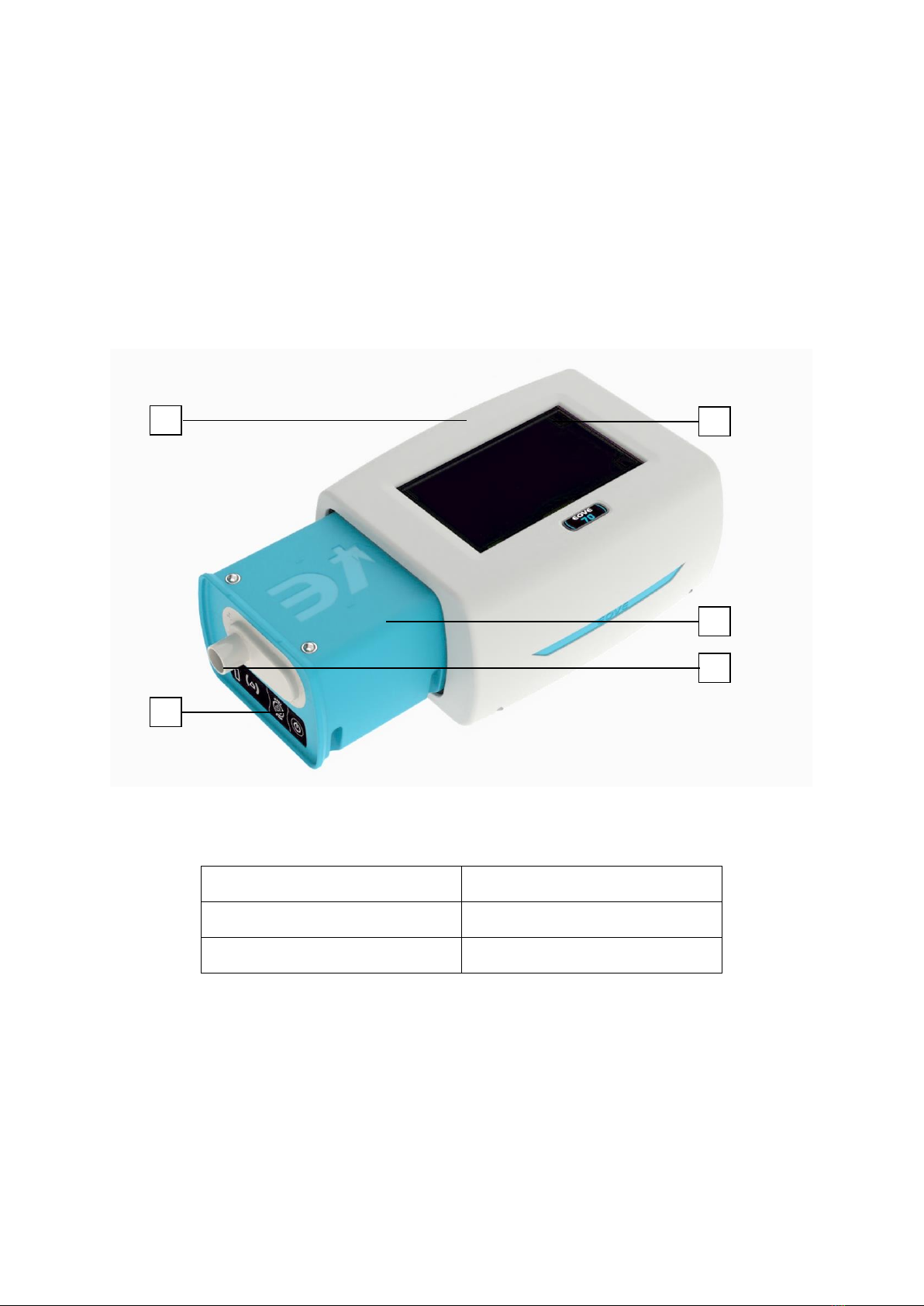
FRONT PANEL
EOVE-70 –Removable module
1. EO-Display housing unit
2. Display screen
3. Keyboard
4. SDM module
5. Circuit port
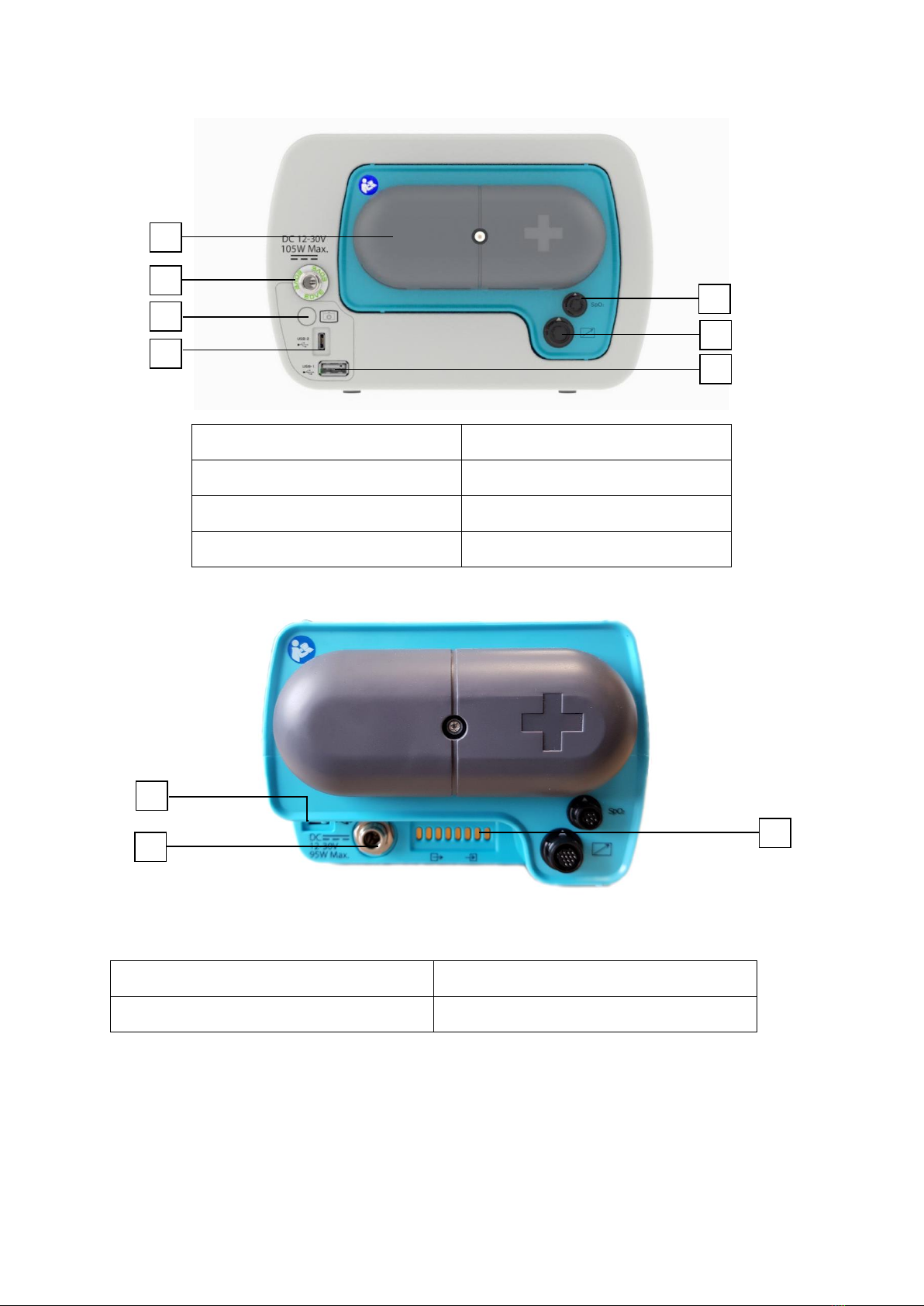
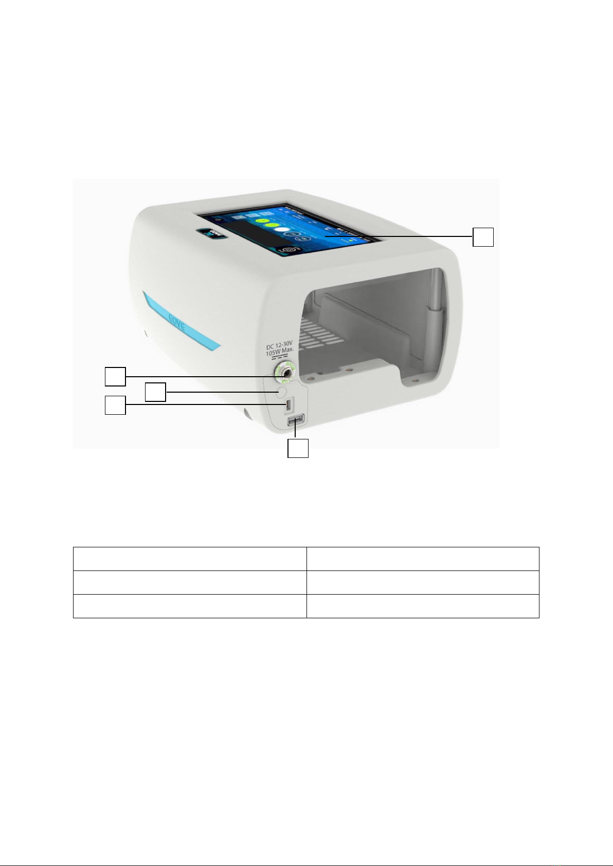
REAR PANEL
1
3
2
4
5
Technical Manual –EOVE-70 MANAGEMENT
12
1. Air inlet/outlet filters cover
2. SpO2 plug
3. DC Power plug
4. Remote control plug
5. Standby button
6. USB port 1
7. USB port 2
REAR VIEW OF DEVICE WITHOUT DOCKING STATION
1. USB port
2. Electrical connection to housing unit
3. DC Car charger connection
1
3
5
2
4
3
2
1
7
6
Technical Manual –EOVE-70 MANAGEMENT
13
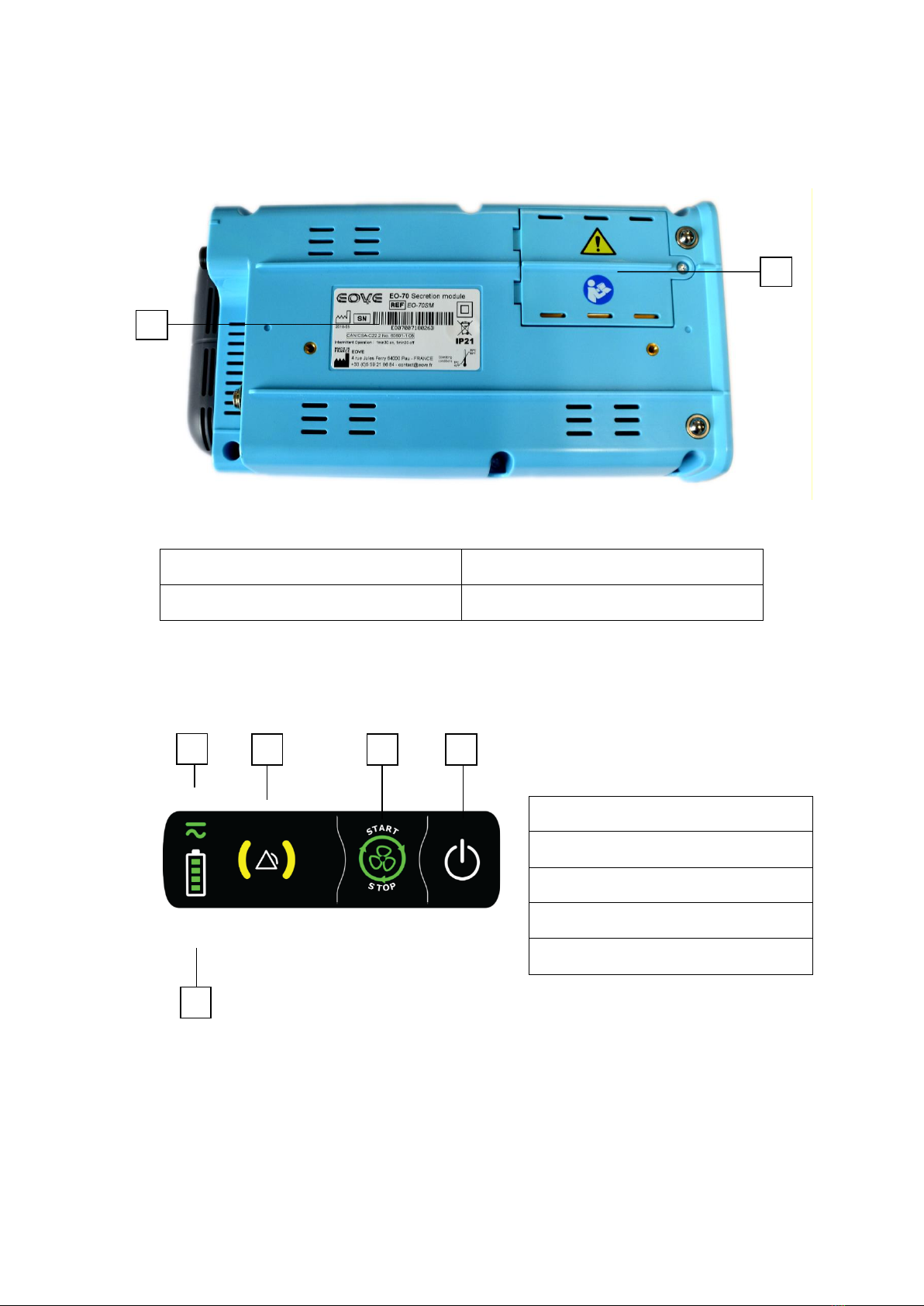
VIEW FROM BELOW OF EOVE-70 SMD MODULE
1. Module label with serial number
2. Battery flap
KEYBOARD
1. Power source indicator
2. Alarm indicators
3. Treatment start / stop button
4. Power on/off button
5. Battery level indicator
1
2
1
2
3
4
5
Technical Manual –EOVE-70 MANAGEMENT
14
EO-DISPLAY HOUSING UNIT
The EO-Display housing permits to control the EOVE-70 SMD module when it is inserted inside. The
screen of the unit displays various information from the EOVE-70 SMD module and enables to set the
different parameters.
EO-Display housing unit –Inputs and outputs
1. DC Plug
4. USB connector
2. On/Off button
5. Display screen
3. Micro USB connector
1
2
3
4
5
Technical Manual –EOVE-70 MANAGEMENT
15
2.2 The Technical data
For technical data, refer to the EOVE-70 user guide.
2.3 Structure and operation
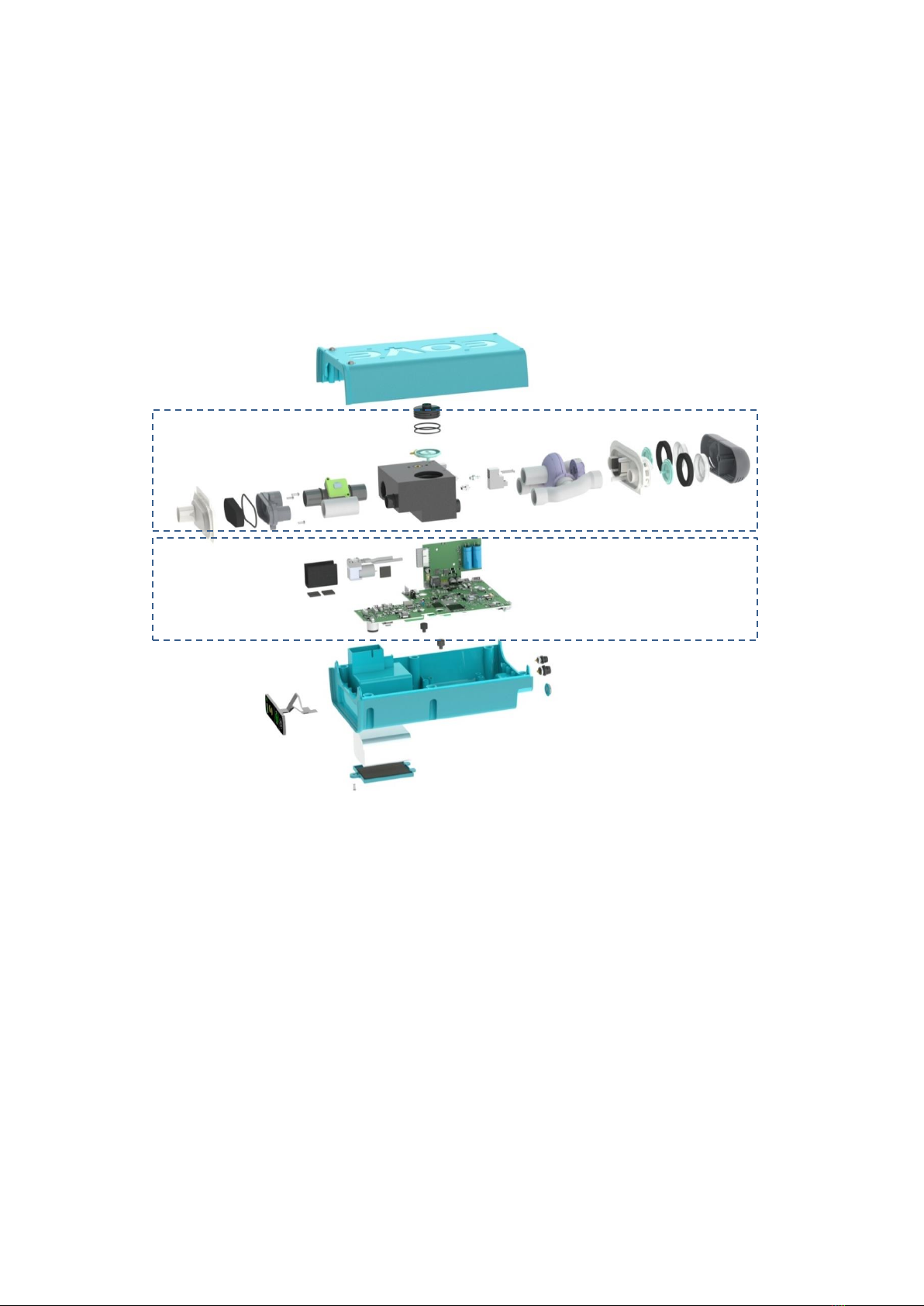
2.3.1 EOVE-70 SMD module structure
EOVE-70 SMD module architecture
Pneumatic
subassembly
Electrical
subassembly
Technical Manual –EOVE-70 MANAGEMENT
16
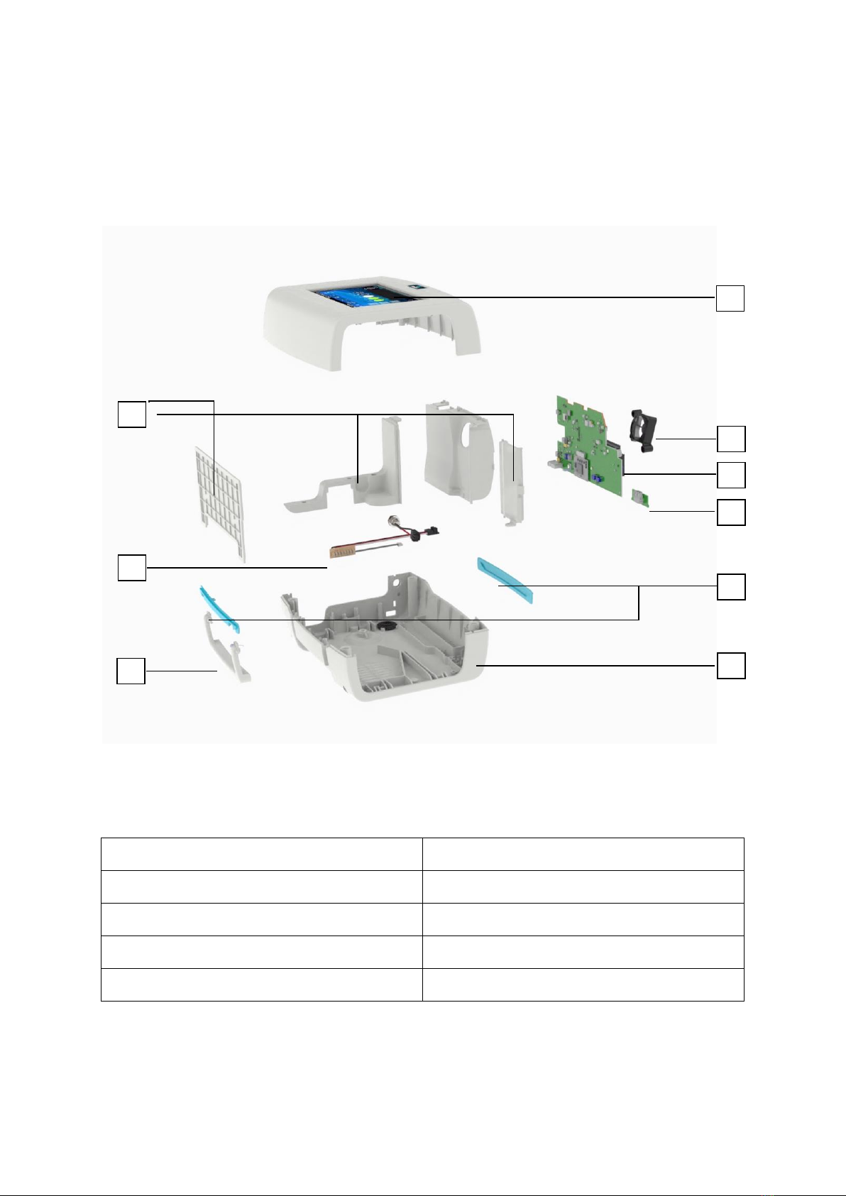
2.3.2 EO-Display housing unit structure
EO-Display Housing unit architecture
1. Upper shell & display screen
6. Lower shell
2. Cooling fan
7. Covers
3. EO-Display CPU board
8. Connection board & DC plug cable
4. USB board
9. Handle
5. Insert
1
2
3
4
7
8
5
9
6
Technical Manual –EOVE-70 MANAGEMENT
17
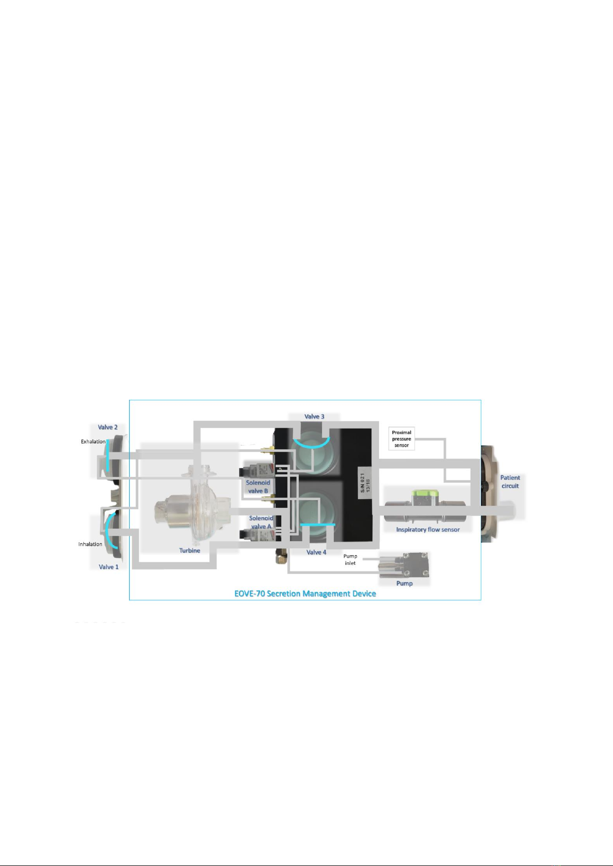
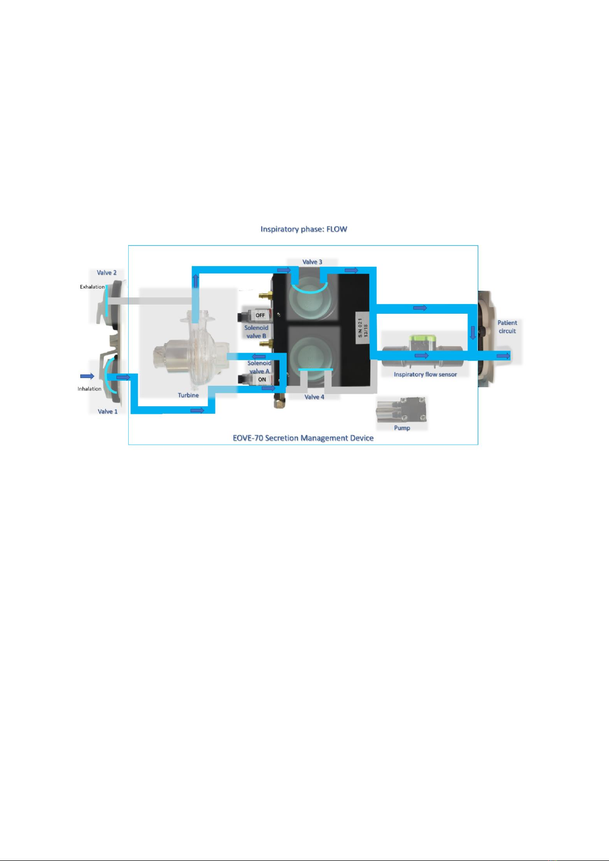
2.3.3 Operation of EOVE-70 SMD module
The operation of the EOVE-70 secretion management device is based on a closed control loop of the
proximal pressure. There are two distribution mode, automatic and manual. In both modes, a pressure
set point is send to the main actuator, the turbine. This pressure set point affectsdirectly turbine speed
which is proportional to pressure evolution. A high pressure set point will increase the turbine speed.
This pressure is measured by the proximal pressure sensor. Thus, the determination of distribution
parameters, especially the flow ramp rate affects the level of the turbine acceleration at the start of
each phase of respiratory cycle.
At the same time, the two solenoid valves control the four valves to manage phases of respiratory
cycles. A solenoid valve controls two valves during inhalation phase and the other one, the two others
during exhalation phase.
The measurement of inspiratory flow completes the system to calculate the peak flow and the tidal
volume on each respiratory cycle.
NOTE: When the EOVE-70 SMD is switched on but the ventilation is off, the turbine stills operate to
remain cool. There are two speeds for cooling during standby. Below 45°C the turbine speed is low,
and above the temperature threshold, the speed is higher. That is why there is always a low ambient
noise when the device is on.
Technical Manual –EOVE-70 MANAGEMENT
18
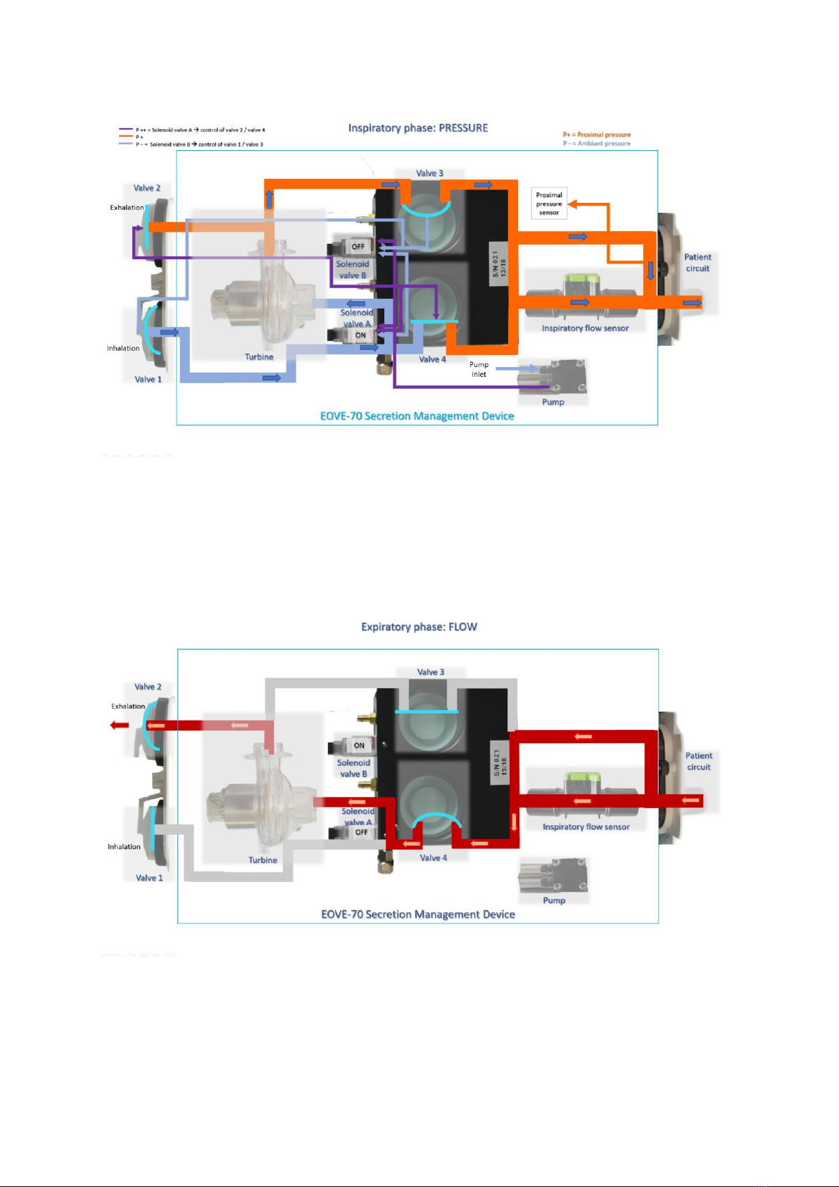
Operation of EOVE-70 SMD during inspiratory phase
During inspiratory phase, the EOVE-70 secretion management device provides positive pressure to the
patient. This pressure value depends on the set point configurated by the user and is proportional to
the turbine speed.
The air is inhaled through valve 1, and flows toward the turbine, then the valve 3 and the inspiratory
flow sensor.
During inspiratory phase, the low pressure (blue circuit on the drawing below) is equal to the
atmospheric pressure. The high pressure (orange circuit)provided by the turbine is equal to the
proximal pressure received by the patient. The difference of pressure between the two circuits is
positive.
Meanwhile, the pump enables to provide additional pressure to the two solenoid valves to control the
four valves. The solenoid valve A switches on to close valve 2 and valve 4. The solenoid valve B is turned
off, so the valves 1 and 3 are opened to permit the air to flow toward the patient.
Technical Manual –EOVE-70 MANAGEMENT
19
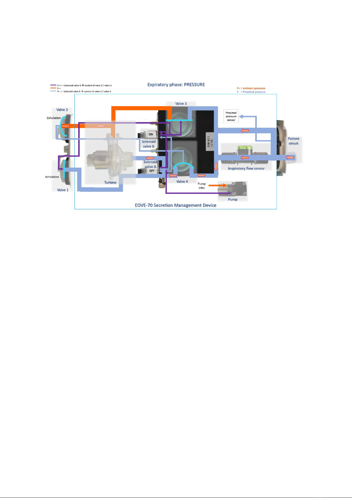
Operation of EOVE-70 SMD during expiratory phase
During the expiratory phase, the EOVE-70 secretion management device creates a suction to assist the
patient when he coughs. The air flows through the inspiratory flow sensor, the valve 4, then the turbine
and is exhaled by the valve 2.
During the expiratory phase, the low pressure is equal to the proximal pressure and the high pressure
is equal to atmospheric pressure. The difference of pressure between the two circuits is negative.
Technical Manual –EOVE-70 MANAGEMENT
20
The pump still provides additional pressure to the two solenoid valves to control the four valves.
However, during the expiratory phase, the solenoid valve B turns on to close the valve 1 and the valve
3 and the solenoid valve A switches off to open the valve 4 and the valve 2 to permit the exhalation.
Table of contents
Other eove Medical Equipment manuals


Popular Medical Equipment manuals by other brands


Getinge
Getinge Arjohuntleigh Nimbus 3 Professional Instructions for use

Mettler Electronics
Mettler Electronics Sonicator 730 Maintenance manual

Pressalit Care
Pressalit Care R1100 Mounting instruction

Denas MS
Denas MS DENAS-T operating manual

bort medical
bort medical ActiveColor quick guide

AccuVein
AccuVein AV400 user manual


