Forza FDC-2012R-I User manual

2-
year
warranty
Ajustes 05_19_2017
User Manual
Uninterruptible Power Supply System
FDC-2012R-I / FDC-3012R-I

Table of content
1. Introduction
1.1 Transportation
1.2 Preliminary steps
1.3 Initial setup
1.4 Important safety instructions
1.5 Maintenance, service and faults
2. Operation
2.1 Unpacking and inspection
2.2 UPS front and rear panel views
2.3 Installation procedure
2.4 UPS connections
2.5 Turning on the UPS
2.6 Battery replacement
2.7 ForzaTracker monitoring software
3. Advanced operation
3.1 Button and function description
3.2 LCD panel
3.3 Audible alarm
3.4 Abbreviations on the LCD display
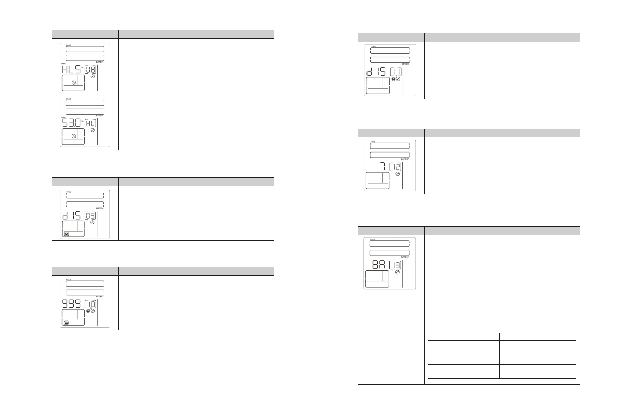
3.5 UPS parameter settings
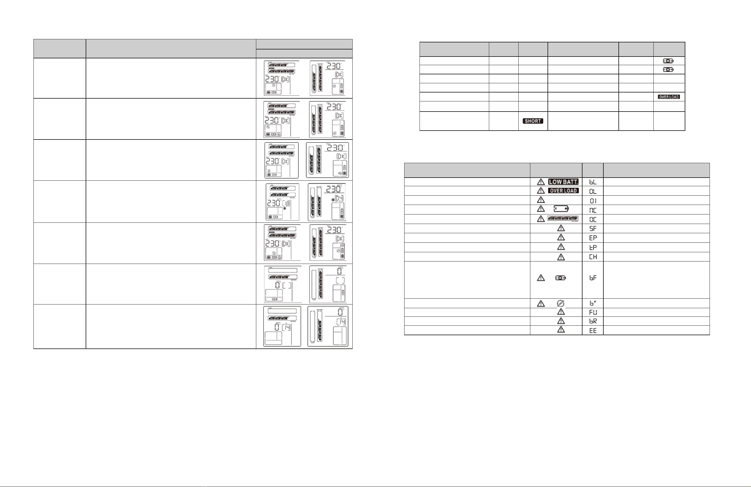
3.6 Operation mode description
3.7 Fault codes
3.8 Warning indicators
4. Troubleshooting
5. Storage and maintenance
6. Technical specifications
1. Introduction
Thank you for purchasing the Forza FDC-2012R-I and FDC -3012R-I Online UPS. To enjoy all the features and benefits of this unit,
please read and follow all installation and operation instructions thoroughly before unpacking, installing or operating this device. After
you have read this manual, keep it in a safe place for future reference.
The information contained in this manual covers the 2000VA / 3000VA uninterruptible power system, its basic functions, operating
procedures, options available and troubleshooting guide. It also includes information on how to ship, store, handle, and install the
equipment.
1-1. Transportation
• Make sure to transport the UPS system only in the original package to protect it against shock and impact.
1-2. Preliminary steps
• Water condensation may occur if the UPS is unpacked in a very cold environment and then moved to a warmer location.
• The UPS must be thoroughly dry before being installed. Failure to do so may increase the risk of electric shock.
• Do not install the UPS system near water or in moist environments.
• Do not install the UPS system where it would be exposed to direct sunlight or near a heater or heating vent.
• Do not block ventilation holes in the UPS housing.
1-3. Initial setup
• Do not connect appliances or equipment that may overload the UPS system (such as a laser printer) to the output sockets.
• Place cables in such a way that no one can step on or trip over them.
• Do not connect domestic appliances, such as hair dryers, to the UPS output sockets.
• Connect the UPS system only to an earthed shockproof outlet which must be easily accessible and close to the UPS system.
• Please only use certified electrical cables for input and output connections.
• During the installation of this equipment, make sure that the sum of the leakage currents of the UPS and the connected loads shall
not exceed 3.5 mA.
CAUTION: The unit is heavy. Lifting the unit requires a minimum of two people.
1-4. Important safety instructions
• Do not disconnect the mains cable on the UPS system or the building wiring outlet (shockproof socket outlet) at any time, since this
would cancel the protective earth of the UPS system and of all connected loads.
• Connect the UPS only to a grounded socket that meets electrical safety guidelines.
• Locate the UPS near a wall socket. Do not use an extension cord between the UPS and the socket.
• In the event of an emergency, press the OFF/Enter button and disconnect the power cord from the AC mains to properly disable the
UPS.
• Do not allow any kind of liquid or foreign object to enter this UPS unit. Do not place beverages or any other containers with liquid on
or nearby the unit.
• The UPS can be operated by any individual with no previous experience.
1-5. Maintenance, service and faults
• The voltage used by this UPS may be hazardous. The unit contains no user serviceable parts; do not attempt to disassemble the unit.
Only qualified service technicians can perform maintenance on the unit. Failure to adhere to this could cause personal injury or
equipment malfunction and void the warranty.
• Caution: - risk of electric shock. Even after the unit is disconnected from the mains, components inside the UPS system are still
connected to the battery packs which are potentially dangerous.
• Before carrying out any kind of service and/or maintenance, disconnect the batteries and verify that no current is present and no
hazardous voltage exists in the terminals of high capacity capacitors, such as BUS-capacitors. Servicing of batteries should be
performed or supervised by experts who possess the knowledge to closely follow all required precautions.
• To avoid electrical shock, turn off the unit and unplug it form the AC power source before servicing the battery.
• Caution: potentially hazardous voltages from the battery can still be present even after disconnecting the UPS from the AC mains.
Therefore, the positive and negative terminals of the battery shall de disconnected prior to performing any maintenance or repair
inside the unit.
• A battery can present the risk of short-circuit current and electrical shock. The following precautions should be taken:
- Remove wristwatches, rings and other metal objects

- Use only tools with insulated grips and handles.
- Wear rubber gloves and boots.
- Do not lay tools or metal parts on top of batteries.
- Disconnect charging source prior to connecting or disconnecting battery terminals.
- Determine if battery is inadvertently grounded. If inadvertently grounded, remove source from ground. Contact with any part of a
grounded battery can result in electrical shock. The likelihood of such shock can be reduced if such grounds are removed during
installation and maintenance.
• When replacing the battery, make sure to use the same type and number of sealed lead-acid batteries specified.
• Do not dispose of batteries in a fire. Batteries may explode if exposed to high temperatures.
• Never try to open a battery. The cell contains a toxic electrolyte which is harmful to the skin and eyes.
• Replace the fuse only with the same type and amperage in order to avoid fire hazards.
• Do not dismantle the UPS system.
2. OPERATION
2-1. Unpacking and inspection
Remove the UPS from its package and make sure that all the following items are included:
• One UPS unit
• One monitoring software CD (ForzaTracker)
• One USB cable
• One 16A IEC C19 to 5-15P
• One 16A IEC C19 to CEI 23-50
• One 16A C19 to IRAM 20736
• Two C14 to 5-15R cables
• Rack mounting hardware
• Tower support base
• One user manual
• Warranty certificate
Carefully inspect the UPS to check for any damages that may have occurred during shipping.
Should any evidence of damage be found or if some parts are missing, do not turn the UPS on; you must immediately notify the carrier
or dealer where you purchased the unit.
2-2. UPS diagram
Front view Rear view
FDC -2012R-I
FDC -3012R-I
1. Programmable outlets for non-critical loads
2. Dedicated outlets for critical loads
3. AC input
4. Modem/phone/network surge protection
5. USB communication port
6. RS-232 communication port
7. SNMP intelligent slot
8. Emergency Power off connector (EPO)
9. External battery connection
10. Cooling fan(s)
2.3. Installation procedure
Choose location
Install the UPS unit in any protected environment that provides adequate airflow around the unit, and free from excessive dust, corrosi-
ve fumes and conductive contaminants. Do not operate your UPS in an environment where ambient temperature or humidity is high.
For best performance, keep the indoor temperature between 0° C and 45° C. Place the UPS unit at least 20cm away from monitors to
avoid interference.
2.3.1 Initial setup
• For safety considerations, the UPS is shipped out from the factory with battery wires disconnected.
• Before installing the UPS, the user must first reconnect the wires. To do so, follow the steps illustrated below.
This UPS can be either placed on a desktop, mounted in a rack or installed in an upright position. Define the proper display orientation
based on the configuration chosen to install this UPS.
Rack-mount installation
The unit comes with mounting brackets for the standard 19-inch (46.5cm) rack.
Step 1
Remove the front panel.
Step 2
Connect the AC input and then
reconnect battery wires.
Step 3
Replace the front panel.
Step 1 Step 2

Tower installation
Allows the user to install the UPS in the upright position.
2-4. UPS connections
2.4.1 Connection to an external battery pack
Make sure to follow the correct polarity when connecting external battery packs. Connect the positive pole of the battery pack to the
positive pole of the external battery terminal in the UPS, and the negative pole of the battery pack to the negative pole of the external
battery terminal of the unit.
Reverse polarity may cause an internal fault. It is recommended to add one breaker between the positive pole of battery pack and the
positive pole of the external battery connector in the UPS to prevent damaging the batteries.
The required specification of the breaker is: voltage ≥1.25 x battery voltage/set; current ≥50A
Choose the battery size and quantity based on the backup time requirement and the UPS specifications. To extend battery life, the
operating temperature range should be between 15ºC and 25ºC.
2-4.2 UPS input connection
Plug the UPS into a two-pole, three-wire, grounded receptacle only.
Avoid using extension cords or adapter plugs.
Note: Verify if the site wiring fault indicator lights up in the LCD panel. It will be illuminated when the UPS is plugged into an improperly
wired utility power outlet (Refer to the troubleshooting section). Also check if there is a circuit breaker against overcurrent and short
circuit between the mains and AC input of the UPS.
The recommended protection value is 16 amperes for the 2K and 3K models.
2-4.3 UPS output connection
For socket-type outputs, there are two kinds of outputs: programmable outlets and general outlets for mission critical loads. During
power failure, you may extend the backup time to critical devices by setting shorter backup times for non-critical devices.
Step 1
Unfold and align the tower
support base.
Step 2
Place the UPS vertically on the
base.
Step 3
Verify that the UPS is stable
and firmly attached to the base.
Intelligent slotRS-232 portUSB port
To allow for unattended UPS shutdown/start-up and status monitoring, connect one end of the communication cable to the
USB/RS-232 port, and the other end to the communication port of your PC. With the monitoring software installed, you can schedule
UPS shutdown/start-up and monitor its status through a PC.
The UPS is equipped with an intelligent slot perfect for either SNMP or AS400 card. When installing either SNMP or AS400 card in the
UPS, it will provide advanced communication and monitoring options.
Note: The USB port and RS-232 port cannot be used at the same time.
Connect the network surge protection
The UPS has two RJ45 connectors for network lines.
• Connect a single line modem/phone/fax cable into the network surge-protection “IN” jack on the rear panel of the UPS.
• Connect a network cable from the OUT jack on the rear of the UPS to a port on a PC or network device such as router.
2.4.4 Disabling and enabling the EPO function
Keep pins 1 and 2 closed for UPS normal operation. To activate the EPO feature, remove the wire between pin 1 and 2.
2.5 Turning on the UPS
Press the ON/Mute button on the front panel for two seconds to power on the UPS.
Note: The battery charges fully during the first five hours of normal operation. Do not expect full battery run capability during this initial
charge period.
2.6 Battery replacement (Service personnel only)
NOTICE: This UPS is equipped with internal batteries and only qualified service personnel shall be allowed to replace the batteries.
Note: Once the batteries are removed, the connected equipment is no longer protected from power outages.
CAUTION! Make sure to follow all safety precautions and warnings during the replacement procedure.
IN OUT
Closed for UPS normal
operation
To enable the EPO function, remove
the two screws
Step 1
Remove the front panel of
the UPS.
Step 2
Disconnect the battery wire.
Step 3
Remove the two screws and
proceed to pull out the battery
compartment
Communication ports
BREAKER

Rack display
Load info
Load info
Battery info
UPS status
Battery info
Warning & Fault info/
Setting operation
Backup time
info
Input/output
and Battery info
Warning & Fault info/
Setting operation
Backup time
info
Input/output
and battery info
UPS status
Tower display
Step 4
Remove the top cover of
the compartment and
replace the batteries.
Step 5
When done, replace the cover of
the battery compartment and
screw it to the unit chassis.
Step 6
Reconnect the battery wires
Step 7
Replace the front panel of
the UPS.
2.7 ForzaTracker monitoring software
ForzaTracker is a new generation of UPS monitoring software, which provides user-friendly interface to monitor and control your UPS
system. This unique software provides safe auto-shutdown for multi-computer systems during power failures. With this software, users
can monitor and control any UPS on the same LAN no matter how far they might be from the UPS.
Installation procedure for Windows users:
1. Use the supplied CD or go to the website: http://www.forzaups.com/us/driver-downloads/.
2. After clicking the software icon, choose the required operation system.
3. Follow the on-screen instructions to install the software.
4. When you finished downloading all required files, enter the serial No (installation password): 5242-87f6-64re-di8d-986u to install the
software (include the hyphens).
5. In order to access as Administrator, input the password: 111296.
6. When your computer restarts, the management software will appear as a light blue round icon located in the system tray, near the
clock.
Note: For Mac and Linux users, please refer to the ForzaTracker user guide found in our website.
3. Advanced operation
3-1. Description of buttons and functions
3-2. LCD panel
ON/MUTE SELECT OFF/ENTER
FunctionButton
ON/Mute
button
OFF/Enter
button
Select
button
ON/Mute
+ Select
button
Turn on the UPS: Press and hold the ON/Mute button for at least 2 seconds to turn on the
UPS.
Mute the alarm: When the UPS is on battery mode, press and hold this
button for at least 3 seconds to disable or enable the alarm system.
This command would not apply when warnings or errors occur.
Up key: Press this button to display previous selection in the UPS configuration menu.
Switch to UPS self-test mode: Press and hold ON/Mute button for 3 seconds to perform the
self-test in AC mode, ECO mode, or converter mode.
•
•
•
•
Turn off the UPS: Press and hold this button for at least 2 seconds to turn off the UPS in
battery mode. The UPS will remain in standby mode under normal power conditions or transfer
to Bypass mode provided it has been enabled previously by pressing this button.
Confirm selection key: Press this button to confirm the selection in the UPS configuration
menu.
•
•
Switch LCD message: Press this button to change the LCD message for input voltage, input
frequency, battery voltage and output voltage, output frequency.
Setting mode: Press and hold this button for 3 seconds to enter the UPS configuration menu
while UPS is in standby or bypass mode.
Down key: Press this button to display the next selection in the UPS configuration menu.
•
•
•
Switch to bypass mode: When the utility power is normal, press ON/Mute and Select
buttons simultaneously for 3 seconds to transfer the UPS to bypass mode. This action will be
ineffective if the input voltage is not within an acceptable range.
Exit setting mode or return to the upper menu: When the UPS is on setting mode, press
the ON/Mute and Select buttons simultaneously for 0.2 seconds to return to the upper menu.
If it is already in top menu, press these two buttons at the same time to exit the setting mode
•
•
Select +
OFF/Enter
button
Rack or Tower display switch: Press the Select and OFF/Enter buttons simultaneously for 3
seconds. The display changes from/to Rack to/from Tower.
•

3-3. Audible alarm
3-4. Abbreviations on the LCD display
3-5. UPS parameter settings
Battery mode
Low battery
Overload
Fault
Bypass mode
Sounds every 5 seconds
Sounds every 2 seconds
Sounds every 0.5 second
Continuous sound
Sounds every 10 seconds
Two parameters need to be configured in order to set up the
UPS. Refer to the following diagram.
Parameter 1: it is used for the different configuration options.
Please refer to the table below.
Parameter 2: it represents the setting information or values
of each program.
Parameter 2
Parameter 2
Parameter 1
Parameter 1
Display Function
Backup time information
Configuration and fault information
Mute function
25%
LOAD
50% 75% 100%
BATTERY
25% 50% 75% 100%
Indicates the remaining backup time in pie chart or in numbers
H: hour, M: minute.
Indicates that configuration parameters are being set.
Warning and fault code indicators. The meaning of the codes is listed
in the section below.
Indicates that the UPS alarm is disabled
Input/Output and battery information
Indicates input voltage, input frequency, battery voltage, output
voltage and output frequency. V: voltage, Hz: frequency
Indicates that the programmable management outlets are working.
Indicates that the UPS is connected to utility power
Indicates that the battery is working
Indicates the charging status
Indicates the UPS is working in bypass mode.
Indicates the UPS is working in ECO mode.
Indicates the UPS is working in converter mode.
Battery level indicator at 0-24%, 25-49%, 50-74%, and 75-100% of its
capacity.
Low battery level indicator.
Battery fault indicator.
Load level indicator at 0-24%, 25-49%, 50-74%, and 75-100% of its
capacity
Overload indicator
Indicates the load or the UPS output is short circuited.
Load information
Programmable outlet status
Mode of operation
Battery information
ENA
DIS
ESC
HLS
LLS
AO
AC
EAT
RAT
OK
ON
SD
BL
OL
OI
NC
OC
SF
EP
TP
CH
BF
BV
FU
BR
EE
Enable
Disable
Escape
High loss
Low loss
Enable when opened
Enable when closed
Estimated runtime
Remaining runtime
OK
ON
Shut down
Battery low
Over load
Input current exceeds allowable limit
No battery connected
Overcharge
Site wiring fault
EPO
Temperature
Charger failure
Battery fault
Input voltage is out of bypass range
Frequency is unstable in bypass mode
Replace battery
EEPROM error
Abbreviation Display content Meaning

01: Output voltage settings
02: Frequency converter enable/disable
03: Output frequency settings
04: ECO enable/disable
05: ECO voltage range setting
06: Bypass enable/disable
07: Bypass voltage range setting
Interface Setting
Interface Setting
Interface Setting
Interface Setting
Interface Setting
Interface Setting
Interface Setting
Parameter 2: Output voltage
For 200/208/220/230/240 VAC, you may choose any of the
following output voltages
200: The output voltage is 200VAC
208: The output voltage is 208VAC
220: The output voltage is 220VAC
230: The output voltage is 230VAC (Default)
240: The output voltage is 240VAC
Parameter 2: Activates or cancels the converter mode. You
may choose one of the options below:
CF ENA: Enable converter mode
CF DIS: Disable converter mode (Default)
Parameter 2: Use this menu to define the initial frequency
on battery mode:
BAT 50: The output frequency is set to 50Hz
BAT 60: The output frequency is set to 60Hz
If the converter mode is enabled, the following options will
be available:
CF 50: The output frequency is set to 50Hz
CF 60: The output frequency is set to 60Hz
Parameter 2: Activates or cancels the ECO mode. Two
options are available:
ENA: ECO mode enable
DIS: ECO mode disable (Default)
Parameter 2: Use this menu to set the acceptable high voltage
point and low voltage point for ECO mode by pressing Down
key or Up key.
HLS: High loss voltage in ECO mode.
For 200/208/220/230/240 VAC models, the setting range in
parameter 3 is from +7V to +24V of the nominal voltage.
(Default: +12V)
LLS: Low loss voltage in ECO mode.
For 200/208/220/230/240 VAC models, the setting range in
parameter 3 is from -7V to -24V of the nominal voltage. (Default:
-12V)
Parameter 2: Use it to activate or cancel the bypass feature
when the UPS is off.
ENA: Bypass enabled
DIS: Bypass disabled
Parameter 2: Press the UP or Down key to choose the
acceptable high and low voltage values for Bypass operation
HLS: High voltage adjustment in bypass mode
For 200/208/220/230/240 VAC:
230-264: High voltage setting ranges from 230VAC to 264VAC
as set in parameter 3. (Default: 264VAC)
LLS: Low voltage adjustment in bypass mode. For
200/208/220/230/240 VAC:
170-220: Low voltage setting ranges from 170VAC to 220VAC
as set in parameter 3. (Default: 170VAC)

11: Backup time setting for general outlets
08: Bypass frequency range setting
Interface Setting
Interface Setting
Parameter 2: Use this setting to configure the backup time on
battery mode for general outlets.
0-999: Sets the backup time in minutes, from 0-999 for general
outlets on battery mode.
DIS: Disables the runtime limit timer, in which case backup time
will depend on battery capacity. (Default)
Note: When setting this parameter to “0”, the backup time will
only last 10 seconds.
Parameter 2: Use this menu to set the acceptable high
frequency point and acceptable low frequency point for Bypass
mode by pressing the Down key or Up key.
HLS: Bypass high frequency point
For 50Hz output frequency models:
51-55Hz: Sets the frequency high loss point from 51Hz to 55Hz
(Default: 53.0Hz)
For 60Hz output frequency models:
61-65Hz: Sets the frequency high loss point from 61Hz to 65Hz
(Default: 63.0Hz)
LLS: Bypass low frequency point
For 50Hz output frequency models:
45-49Hz: Sets the frequency low loss point from 45Hz to 49HZ
(Default: 47.0Hz)
For 60Hz output frequency models:
55-59Hz: Sets the frequency low loss point from 55Hz to 59Hz
(Default: 57.0Hz)
09: Programmable outlets enable/disable
Interface Setting
Parameter 2: Activates or cancels the programmable outlet
feature.
ENA: Programmable outlets enabled
DIS: Programmable outlets disabled (Default)
10: Backup time setting for programmable outlets
Interface Setting
Parameter 2: Sets the backup time limits for the programmable
outlets.
0-999: Use this setting to define the programmable outlets
backup time in minutes, from 0-999, in order to connect
non-critical devices on battery mode. (Default:999)
12: Battery total Ah setting
Interface Setting
Parameter 2: Use this setting to configure the total battery
capacity in Ah for the UPS system.
7-999: Sets the battery total capacity from 7-999 in Ah.
Please set the correct battery total capacity if an external
battery bank is connected.
13: Maximum charger current setting
Interface Setting
Parameter 2: Use this setting to configure the charger current
to be applied.
For low voltage models with 24/36/48VDC
1/2/4/6/8: sets the charger maximum current to 1/2/4/6/8
amperes. (Default: 2A)
For high voltage models with 24/36/48VDC
1/2/4/6/8/10/12: set the charger maximum current to
1/2/4/6/8/10/12 amperes. (Default: 2A)
For low voltage and high voltage model with 72/96VDC
1/2/4/6/8: sets the charger maximum current to 1/2/4/6/8
amperes. (Default: 2A)
Note: set the appropriate charger current based on the capacity
of the battery used. The recommended charging rate of
0.1C~0.3C according to battery capacity is included in the table
below:
Battery capacity(Ah)
7~20
20~40
40~60
60~80
80~100
100~150
Total charging current (A)
2
4
6
8
10
12

14: Charger boost voltage setting
Interface Setting
Parameter 2: Use this setting to configure the boost voltage
level.
2.25-2.40: Sets the charger boost voltage from 2.25 to 2.40
V/cell. (Default is set at 2.36V/cell)
15: Charger float voltage setting
Interface Setting
Parameter 2: Use this setting to determine the float voltage
level.
2.20-2.33: Sets the charger float voltage from 2.20 to 2.33V/cell
(Default is 2.28V/cell)
16: EPO relay setting
Interface Setting
Parameter 2: Use this setting to configure the EPO circuit
control.
AO: Active Open (Default). When AO is selected as the normal
configuration, it will enable the EPO function when Pin 1 and
Pin 2 are opened.
AC: Active Close. When AC is selected as the normal configu-
ration, it will enable the EPO function when Pin 1 and Pin 2 are
closed.
17: External output isolation transformer
Interface Setting
Parameter 2: Allow or disallow the connection of an external
output isolation transformer
ENA: If selected, the UPS will be allowed to connect to an
external output isolation transformer.
DIS: If selected, the UPS will be denied to connect to external
output isolation transformer. (Default)
18: Runtime setting display
Interface Setting
Parameter 2: Use this setting to configure the runtime on the
display.
EAT: If EAT is selected, it will show the estimated runtime on
the screen (Default)
RAT: If RAT is selected, it will show the runtime accumulated up
to this point.
19: Acceptable input voltage range setting
Interface Setting
Parameter 2: Use this menu to set the acceptable high voltage
point and acceptable low voltage point for the input voltage by
pressing the Down or Up key.
HLS: Input high-voltage point
For 200/208/220/230/240 VAC models:
280/290/300: sets the high-voltage point in parameter 2.
(Default: 300VAC)
LLS: Bypass low-voltage point
For 200/208/220/230/240 VAC models:
110/120/130/140/150/160: sets the low-voltage point in
parameter 2. (Default: 110VAC)
00: Exit setting
Interface Setting
Exits the configuration mode.

3-6. Operation mode description 3-7. Fault codes
Battery mode
When the input voltage exceeds the acceptable range or
during a power failure, the UPS will start supplying power
from the battery while the alarm will beep every 5 seconds.
Bypass mode
When input is within acceptable voltage range but the UPS
is overloaded, the UPS will transfer to bypass mode or it can
be manually changed to bypass mode using the front panel
controls. The alarm will sound once every 10 seconds in this
case.
Standby mode
The UPS is powered off and there is no power supplied to
the loads; batteries, however, can still be charged.
Fault
The UPS is in fault mode when it fails to provide output
power to the loads. The ERROR icon and the fault code is
displayed on the screen.
Fault event Fault
code IconFault event
01
02
03
11
12
13
14
Fault
code
27
28
2A
41
43
45
49
Icon
x
x
x
x
x
x
x
x
x
x
Battery voltage too high
Battery voltage too low
Charger output shorted
Over temperature
Overload
Charger failure
Input current above the
acceptable limits
Bus start failure
Bus over
Bus under
Inverter soft start failure
High inverter voltage
Low inverter voltage
Inverter output shorted
Operation mode
Online mode
Description LCD display
When the input voltage is within acceptable range, the UPS
will supply pure and stable AC power to connected loads.
The UPS will also charge the battery while in online mode.
ECO mode
(Efficiency
Corrective
Optimizer)
Frequency
converter mode
Energy saving mode:
When the input voltage is within the voltage regulation
range, the UPS will bypass voltage to loads for energy
saving. The UPS will also charge the battery while in ECO
mode.
When input frequency is between 40Hz and 70Hz, the UPS
can be set at a constant output value of 50Hz or 60Hz. The
UPS will still charge the battery while in this this mode.
3-8. Warning indicators
Warning Icon (blinking) Code Alarm
Beeps once every 2 seconds
Beeps once every second
Beeps twice every 10 seconds
Beeps once every 2 seconds
Beeps once every 2 seconds.
(In this case, the UPS turns off
to remind users there is some-
thing wrong with the batteries)
Beeps once every 2 seconds
Low battery
Overload
Excessive input current
Battery is not connected
Overcharge
Site wiring fault
EPO enable
Over temperature
Charger failure
Battery fault
Bypass voltage out of range
Unstable bypass frequency
Battery replacement
EEPROM error
Note: The Site wiring fault function can be enable/disabled via software.
Rack display Tower display

4. Troubleshooting guide
If the UPS system does not operate correctly, use the table below to troubleshoot the problem
5. Storage and maintenance
Maintenance
The UPS system contains no user-serviceable parts. If the battery service life (3~5 years at 25°C ambient temperature) has been
exceeded, the batteries must be replaced. In this case, please contact your dealer or service center.
Storage
Charge the UPS for at least 5 hours before storing the unit. Cover the UPS, and place it upright in a cool, dry location. During storage,
recharge the battery in accordance with the following table
Symptom Possible cause Solution
Even though the mains supply is
normal, there are no status indica-
tors or alarms
Check to make sure the power cord is
firmly connected to a AC wall socket
The AC input cable is not properly
connected
The icon and the warning code
become illuminated on the LCD
display, and the alarm starts
beeping once every 2 seconds
Plug the power cord to a wall socketThe AC input is connected to the
UPS outlet
Set the circuit in its closed position to
disable the EPO function
EPO function is enabled
Rotate mains power socket by 180° and
then connect to UPS system
Line and neutral conductors of UPS
input are reversed
Check if all batteries are properly
connected
The external or internal battery
connection is incorrect
Contact your dealer or service centerBattery voltage is too high or the
charger fails
Please contact the dealer or service
center
Battery voltage is too low or the
charger fails
Remove excess loads from UPS outputUPS is overloaded
Remove excess loads from the UPS
output
Input current is above the accept-
able limits
The icon and the warning code
become illuminated on the LCD
display, and the alarm starts beeping
once every 2 seconds
The and icons become
illuminated on the LCD display and
the alarm starts beeping once every
2 seconds
Fault code 27 and the icon
become illuminated on the LCD
display, and the alarm starts
beeping continuously
Fault code 28 and the icon
become illuminated on the LCD
display and the alarm starts beep-
ing continuously
The , icons and the
become illuminated on the LCD
display, and the alarm starts
beeping every second
Fault code 49 becomes illuminated
and the alarm starts beeping
continuously
Fault code 43 becomes illuminated
along with the icon on the
LCD display, and the alarm starts
beeping continuously
Battery backup time is shorter than
its nominal value
Charge the batteries for at least 5 hours
and then check their capacity. If the
problem persists, consult your dealer
Batteries are not fully charged
Fault code 2A appears on the LCD
display while the alarm beeps
continuously
Check to make sure that the wiring of
the external battery pack connected is
not shorted
Short circuit detected on the char-
ger output
Fault code 45 appears on the LCD
display while the alarm beeps
continuously
Please contact the dealer or service
center
There is no output voltage from the
charger and the battery voltage is
below 10V/PC
Contact your dealer for a replacementDefective batteries
Remove excess loads from the UPS
output
UPS is overloaded. Devices
connected to the UPS are fed
directly from utility power via the
Bypass
Remove excess loads from the UPS
output first. Shut down the UPS com-
pletely before restarting the unit once
again
After repetitive overloads, the UPS
is locked in Bypass mode. Connect-
ed devices are fed directly from
utility power
Remove excess loads from the UPS
output and restart the unit once again
The UPS shuts down automatically
upon detecting the overload condi-
tion in the output
Fault code 14 becomes illuminated
and the alarm starts beeping
continuously
Check the output wiring and if connect-
ed devices are short-circuited
Fault codes 01, 02, 03, 11, 12, 13
and 41 become illuminated on the
LCD display, and the alarm starts
beeping continuously
Please contact the dealer or service
center
The UPS shuts down automatically
upon detecting the overload condi-
tion in the output
A UPS internal fault has occurred.
There are two possible causes:
1. Power is continued to be supplied
to the load, but is done directly from
the AC grid via a bypass
2. Power is no longer supplied to
the load
Batteries must not be discarded as regular household waste! As part of the company’s
eco-friendly approach, we encourage you to follow all applicable local waste regulations
to dispose of your used devices and batteries properly.
-25°C - 40°C
-40°C - 45°C
Every 3 months
Every 2 months
1-2 hours
1-2 hours
Storage temperature Recharge frequency Runtime

6. Technical specifications
Derate capacity to 80% when the output voltage is adjusted to 200VAC or 208VAC.
** If the UPS is installed or used in a place where the altitude is above than 1000m, the output power must be derated one percent per 100m.
***Product specifications are subject to change without further notice.
MPN FDC-2012R-I FDC-3012R-I
General
Capacity
Topology
Input
Nominal voltage
Voltage range (low-line transfer)
Voltage range (low-line comeback)
Voltage range (high line transfer)
Voltage range (high line
comeback)
Frequency
Power factor
Total harmonic distortion (THD)
AC plug style
Output
Nominal voltage
AC voltage regulation
(battery mode)
Frequency (synchronized range)
Frequency (battery mode)
Power factor
Efficiency (AC mode)
Efficiency (battery mode)
Overload
Transfer time (line to battery)
Transfer time (inverter to bypass)
Crest ratio
Harmonic distortion
Waveform
Total outlets
Battery
Battery type and quantity
Recharge time
Charging current
Charging voltage
Communications
LCD display
Audible
Communication ports
Power management software
Environment
Operating temperature
Storage temperature
Relative humidity
Operating altitude
Audible noise
Physical appearance
Dimensions
Weight
Cord length
Additional information
Warranty
2000VA/2000W 3000VA/3000W
Double conversion
200-240VAC
175VAC / 155VAC / 135VAC / 125VAC ± 3%
(based on load percentage 100%-80% / 80%-70% / 70%-60% / 60%-0%)
Low line transfer voltage + 10V
300VAC ± 3%
High line transfer voltage - 10V
40Hz-70Hz
0.99 at 100% load
≤5% at 100% load THDU <1.6%
IEC C20
200/208/220/230/240VAC
± 1%
47-53Hz at 50Hz system / 57-63Hz at 60Hz system
50Hz ± 0.1Hz or 60Hz ± 0.1Hz
1
≥90%
≥88%
AC mode: 100%-110%: 10min / 110%-130%: 1min / >130%: 1sec
Battery mode: 100%-110%: 30sec / 110%-130%: 10sec / >130%: 1sec
0ms
4ms
3:1 (max)
≤2% THD (linear load) / ≤4% THD (non-linear load)
Pure sine wave
8 (IEC C13) 8 (IEC C13)
1 (IEC C19)
12V/9Ah (4) 12V/9Ah (6)
3 hours to 90% capacity
2A ± 10% (default) / 8A ± 10% (max)
82.1VDC ± 1%
Graphical LCD with blue backlight
Battery mode: Sounds every 5 seconds
Low battery: Sounds every 2 seconds
Overload: Sounds once every second
Fault: Continuous sound
SNMP, RS-232, USB
Includes ForzaTracker
32°F-104°F
-4°F-122°F
20-90% non-condensing
<1000m
Every 100m above 1000m decreases output power 1% up to 4000m
<50dB at 1 meter
17.3x3.5x20.1in 17.3x3.5x24.8in
43lb 60.6lb
6.0ft
Two years

This manual suits for next models
1
Table of contents
Other Forza UPS manuals

Forza
Forza HT-752LCD-C User manual

Forza
Forza DC-140USB User manual

Forza
Forza FDC-106KMR-ISO User manual

Forza
Forza FX-1500LCD User manual

Forza
Forza SL402UL User manual

Forza
Forza FDC-1002T-C User manual

Forza
Forza FDC-1502R User manual

Forza
Forza Atlas 2-3KVA User manual

Forza
Forza HT-752LCD-A User manual

Forza
Forza SL-802UL-A User manual

Forza
Forza FDC-1001RUL User manual

Forza
Forza FDC-RT1000VA User manual

Forza
Forza FDC-1000T User manual

Forza
Forza SL-1501UL User manual

Forza
Forza FDC-003K User manual

Forza
Forza XG-1201LCD User manual

Forza
Forza Elipse Series User manual

Forza
Forza FDC-1002T User manual

Forza
Forza FDC-1002T-A User manual

Forza
Forza SL402UL-C User manual