CertaUPS C650 User manual

Scan to download the APP
C650/C650R USER MANUAL
A COMPLETE INSTALLATION
AND USER GUIDE
THE C650 SERIES
An uninterruptible power supply (UPS)
incorporating online double conversion
technology, which eliminates all mains
power disturbances and IOT software
www.certaups.com
For assistance, please contact your local
CertaUPS partner.

C650 & C650R User
Manual Page 4
Table of Contents
SAFETY INSTRUCTIONS............................................................................................................ 6
PRODUCT SAFETY ................................................................................................................... 7
SPECIAL PRECAUTIONS.......................................................................................................... 7
1. INTRODUCTION ............................................................................................................... 8
1.1 Product Features..................................................................................................... 8
1.2 Environmental Protection ...................................................................................... 8
2. PRODUCT OVERVIEW ................................................................................................. 9
2.1 MODEL LIST............................................................................................................... 9
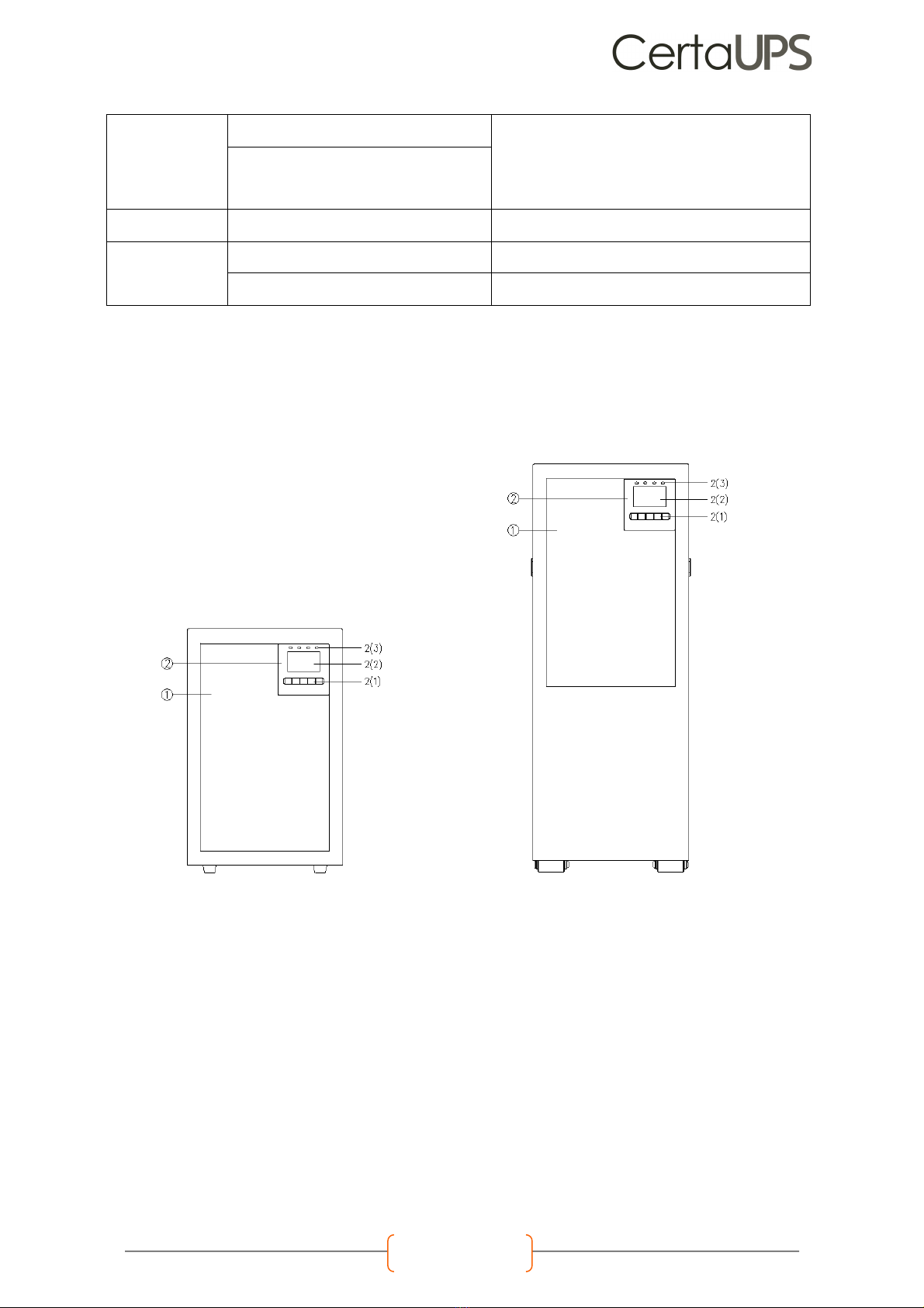
2.2 PRESENTATION ....................................................................................................... 10
2.2.1 C650 Tower Model:........................................................................................ 10
2.2.2 C650R Rack model:....................................................................................... 12
3. INSTALLATION ............................................................................................................ 13
3.2 CHECKING THE ACCESSORY KIT .......................................................................... 14
3.3 MECHANICAL INSTALLATION................................................................................ 15
3.3.1 Tower model........................................................................................................ 15
3.3.2 Rack model........................................................................................................ 15
3.4 Power cables connection ................................................................................... 18
3.4.1 Input /Output wiring specifications................................................................... 18
3.4.2 Wiring for AC Cable (AC source to UPS).......................................................... 18
3.4.3 Wiring with external battery module (C650 / C650R EBM) (DC source to UPS)
........................................................................................................................................ 19
3.4.4 Wiring with RT MBP (MBP source to R/T UPS only) ............................................ 20
4. PARALLEL SYSTEM INSTALLATION AND OPERATION (OPTIONAL) ............................. 21
4.1 WIRING FOR AC CABLE ........................................................................................ 21
4.2 WIRING FOR PARALLEL SIGNAL CABLE ............................................................... 22
4.3 PARALLEL SYSTEM OPERATION ............................................................................. 22
5. OPERATION................................................................................................................ 23
5.1 LCD PANEL ............................................................................................................. 23
5.2 LCD DESCRIPTION ................................................................................................. 24
5.3 DISPLAY FUNCTIONS.............................................................................................. 25
5.4 USER SETTINGS........................................................................................................ 26
5.5 STARTING THE UPS WITH UTILITY............................................................................. 27
5.6 STARTING THE UPS ON BATTERY............................................................................ 27
5.7 UPS SHUTDOWN..................................................................................................... 27

C650 & C650R User
Manual Page 5
6. COMMUNICATION.................................................................................................... 28
6.1 RS232 AND USB ...................................................................................................... 28
6.2 UPS REMOTE CONTROL FUNCTIONS .................................................................... 28
6.3 IOT........................................................................................................................... 29
6.4 Modbus TCP........................................................................................................... 29
6.5 Intelligent Card (optional) ................................................................................... 29
6.6 SOFTWARE.............................................................................................................. 30
6.6.1 Winpower ........................................................................................................... 30
6.6.2 WinPower View APP ...................................................................................... 31
7. UPS MAINTENANCE ...................................................................................................... 32
UPS CARE .......................................................................................................................... 32
7.1 TRANSPORTING THE UPS........................................................................................ 32
7.2 STORING THE UPS................................................................................................... 32
7.3 BATTERY REPLACEMENT ........................................................................................ 33
7.4 REPLACING THE EBM............................................................................................. 33
7.5 RECYCLING A UPS ................................................................................................. 34
8. TROUBLESHOOTING...................................................................................................... 35
8.1 ALARMS & FAULTS.................................................................................................. 35
8.2 SILENCING THE ALARM ......................................................................................... 37
9. TECHNICAL DATA ......................................................................................................... 37
9.1 BLOCK DIAGRAM.................................................................................................. 37
9.2 UPS SPECIFICATION ............................................................................................... 37

C650 & C650R User
Manual Page 6
SAFETY INSTRUCTIONS
The UPS covered in this manual are intended for installation in an environment within 0° - 50°C (excluding batteries)
and free from conductive contaminants.
SYMBOL
DEFINITION
Important instructions that must always be followed
Caution, risk of electric shock – observe the warning associated with the risk of electric shock symbol
EU separate collection and lead content mark for lead acid batteries. Indicates that the battery must not be disposed on as
normal household waste and instead be separately collected and recycled.
EU separate collection mark for waste electrical and electronic equipment (WEEE). Indicates that the item must not be disposed
of as normal household waste and instead be separately collected and recycled.
Information, advice, help
Refer to the user manual
SAFETY OF PERSONS
• RISK OF VOLTAGE BACK FEED. The system has its own power source (the battery). Isolate the UPS and check for
hazardous voltage upstream and downstream during lockout-tagout operation. Terminal blocks may be
energised even if the system is disconnected from the AC power source.
• Dangerous voltage levels are present within the system. It should be opened exclusively by qualified service
personnel.
• The system must be properly grounded.
• The battery supplied with the system contains small amounts of toxic materials. To avoid accidents, the directives
listed below must be observed:
! Servicing of batteries should be performed by personnel knowledgeable about batteries and the
required precautions.
! When replacing batteries, replace with the same type and number of batteries or battery packs.
! Do not dispose of batteries in a fire. The batteries may explode.
! Batteries constitute a danger (electrical shock, burns). The short-circuit current may be very high.
• Precautions must be taken for all handling:
! Wear rubber gloves and boots.
! Do not lay tools or metal parts on top of batteries.
! Disconnect the charging source before connecting or disconnecting battery terminals.
! Determine if battery is inadvertently grounded. If inadvertently grounded, remove source from ground.
Contact with any part of a grounded battery can result in electrical shock. The likelihood of such shock
can be reduced if such grounds are removed during installation and maintenance (applicable to
equipment and remote battery supplies not having a grounded supply circuit).
SAVE THESE INSTRUCTIONS
This manual contains important instructions that should be followed during installation and maintenance of the
UPS and batteries.

C650 & C650R User
Manual Page 7
PRODUCT SAFETY
l The UPS connection instructions and operation described in the manual must be followed in the indicated order.
l UPS enclosure IP rating IP20.
l CAUTION - To reduce the risk of fire, the unit should only be connected to a circuit provided with branch circuit
overcurrent protection.
l The upstream circuit breaker for Normal AC/Bypass AC must be easily accessible. The unit can then be
disconnected from the AC power source by opening this circuit breaker.
l An additional AC contactor is used for back feed protection and must comply with IEC/EN 62040-1
l Disconnection and overcurrent protection devices shall be provided by others for permanently connected AC
input (Normal AC/Bypass AC) and AC output circuits.
l Check that the indications on the rating plate correspond to your AC powered system and to the actual electrical
consumption of all the equipment to be connected to the system.
l For PLUGGABLE EQUIPMENT, the socket-outlet shall be installed near the equipment and shall be easily accessible.
l Never install the system near liquids or in an excessively damp environment.
l Never let a foreign body penetrate inside the system.
l Never block the ventilation grates of the system.
l Never expose the system to direct sunlight or source of heat.
l If the system must be stored before installation, storage must be in a dry place.
l The admissible storage temperature range is -25°C to +55°C without battery (-15°C to +40°C with battery).
l TN-S/IT/TN-C/TT of the electrical supply system may be connected by UPS.
l This UPS may be provided with a maximum of 6 extension battery cabinets or equivalent.
SPECIAL PRECAUTIONS
l The UPS and EBMs are heavy: wear safety shoes and use vacuum lifters preferentially for handling operations.
l All handling operations will require at least two people (unpacking, lifting, installation in rack system).
l Before and after the installation, if the UPS remains de-energized for a long period, the UPS must be energized for
a period of 24 hours, at least once every 6 months (for a normal storage temperature of less than 25°C). This
charges the battery, thus avoiding possible irreversible damage.
l During the replacement of a Battery Module, it is imperative to use the same type and number of batteries as the
original Battery Module provided with the UPS to maintain an identical level of performance and safety.
l This is a category C3 UPS product. In a residential environment, this product may cause radio interference, in
which case the user may be required to take additional measures.

C650 & C650R User
Manual Page 8
1. INTRODUCTION
Thank you for selecting our UPS to protect your electrical equipment.
We recommend that you take the time to read this manual to take full advantage of the many features of your UPS.
Before installing your UPS, please read the safety instructions. Then follow the indications in this manual.
1.1 Product Features
The UPS protects your sensitive electronic equipment from the most common power problems, including power
failures, power sags, power surges, brownouts, line noise, high voltage spikes, frequency variations, switching
transients, and harmonic distortion.
Special characteristics:
• Double converter with pure sine waveform output
• Full digital control
• Output power factor = 1
• High charger capability, the charger current is up to 12Amps
• Smart charging method to expand battery lifetime
• EBM quantity auto-detection
• Communication ports: RPO, Dry in, Dry out, intelligent slot, USB, RS232
• IoT: Ethernet(default) and Wireless (optional)
• Dot-matrix LCD, supports multi-language
• ECO Mode
• Start-able without battery
1.2 Environmental Protection
Products are developed according to an eco-design approach.
Substances
This product does not contain CFCs, HCFCs or Asbestos
Packing
To improve waste treatment and facilitate recycling, separate the various packing components
! The cardboard we use comprises over 50% of recycled cardboard.
! Sacks and bags are made of polyethene.
! Packing materials are recyclable.
! Follow all local regulations for the disposal of packing materials.
Product
The product is mainly made up of recyclable materials.
Dismantling and disassembly must take place in compliance with all local regulations concerning waste. At the end
of its service life, the product must be transported to recycling centres, re-use and treatment facilities for Waste
Electrical and Electronic Equipment (WEEE).
Battery
This product contains lead-acid batteries that must be processed according to applicable local regulations
concerning batteries.
The battery may be removed to comply with regulations and given correct disposal.

C650 & C650R User
Manual Page 9
2. PRODUCT OVERVIEW
2.1 MODEL LIST
1. ‘B’ model means ‘standard model’ with batteries, ‘C’ model means ‘long backup time model’ without
batteries.
2. 16 or 20 batteries could be selected for the UPS and EBM (external Battery Module)
3. The weight in this table is for reference only, please see the labels on the carton for details.
4. Dimension ‘D’ is chassis only, not including the panel.
TOWER MODEL
PRODUCT
NET WEIGHTS (kg)
UNIT SIZE (WxDxH) (mm)
C650-060-C
13.5
225x416x354
C650-100-C
15.5
C650-060-B
57.9
225x416x589
C650-100-B
68.2
EBM
124
RACK MODEL
PRODUCT
NET WEIGHTS (kg)
UNIT SIZE (WxDxH) (mm)
C650R-060-C
13.6
438x540x88(2U)
C650R-100-C
15.5
C650R-060-B
13.3
C650R-100-B
15.2
EBM 240 9AH
60.5
438x559x129(3U)
EBM 240 7AH
56.1
Optional modules and accessories:
If you wish to order other types of function modular or accessories, please contact distributors/partners.
Type
Description
Remark
R MBP
R 6K/10K MBP
For RT 1-1 model only
Intelligent Card
Dry Contact card (C-Relay)
See in chapter 6.5
NMC card (C-NMC)
MODBUS card (C-Modbus)
EMP
Temperature and humidity sensors
WLAN module
WLAN module (C-WIFI)
Wireless connection for IoT
COMM Cable
RS232 CABLE
For RS232 communication
Parallel Kit
For parallel system installing
See in chapter 4.0
Battery cable
Battery cable (16 batt.)
1.8m length,

C650 & C650R User
Manual Page 10
2.2 PRESENTATION
2.2.1 C650 Tower Model:
UPS Module
Front view
1. ventilation area
2. LCD module, including
2(1) button
2(2) LCD screen
2(3) LED indicator
Tower UPS Tower UPS
6-10kVA C model 6-10kVA B model
for UPS connect with user’s own EBM
see in chapter 3.4.3
Battery cable (20 batt.)
for UPS connect with user’s own EBM
Rail kit
Rail kit for R model in Rack installing
See in chapter 3.3.2
Gland kit
Gland kit for R model
For R UPS/MBP model
Gland kit for Tower model
For Tower UPS model

C650 & C650R User
Manual Page 11
Rearview
1. Intelligent slot
2. RS232
3. Ethernet port (RJ45, for IoT
function)
4. USB
5. Wireless (HDMI, For IoT function)
6. RPO& DRY in/out
7. Parallel Slot
8. RJ45 (for EBM detect)
9. AC Input /Output port (Terminal
Block)
10. Input switch
11. External battery port
12. Maintenance bypass switch
(optional, default is yes)
EBM (EXTERNAL BATTERY MODULE)
FRONT VIEW
1. Ventilation area 1. EBM port 1
2. EBM label 2. EBM port 2
i. 3. Fuse board cover
ii. (replace EBM fuse)
iii. 4. EBM detection Box
iv. (RJ45 port)
1
2
3
4
5
6
7
8
9
10
11
12
1
2
3
4
5
6
7
8
9
10
11
12
1
2
3
4
5
6
7
8
9
10
11
12
1
2
3
4
5
6
7
8
9
10
11
12
1
2
3
4
5
6
7
8
9
10
11
12
C650-060-C
C650-100-C
C650-060-B
C650-100-B

C650 & C650R User
Manual Page 12
2.2.2 C650R Rack model:
UPS module
Front view
1. Ventilation area
2. LCD Modular, including 2(1) ---Button,2(2)---LCD screen,2(3)---LED indicator
Rearview
1. INTELLIGENT SLOT
2. RS232
3. Ethernet port (RJ45, for IoT function)
4. USB
5. Wireless (HDMI, For IoT function)
6. RPO& DRY in/out
7. PARALLEL SLOT
8. RJ45 (for EBM detect /RT MBP
detect)
9. AC Input /Output port (Terminal
Block)
10. Breaker of input (only for 1-1
model, optional, default is no)
11. External battery port
EBM (EXTERNAL BATTERY MODULE)
Front view
1. EBM label area
2. EBM label
Rearview
1. Fuse board cover (replace EBM fuse)
2. EBM port 1
3. EBM port 2
4. EBM detection Box (RJ45 port)

C650 & C650R User
Manual Page 13
3. INSTALLATION
It is recommended to move the equipment to the installation site by using a pallet jack or a truck before
unpacking.
The system may be installed only by qualified electricians by applicable safety regulations.
The EBM cabinets are heavy, please install it with at least two people.
3.1 UNPACKING AND INSPECTING
Unpacking the unit in a low-temperature environment may cause condensation to occur in and on
the cabinet. Do not install the unit until the inside and outside of the unit are absolutely dry
(hazard of electric shock).
If any equipment has been damaged during shipment, keep the shipping cartons and packing
materials for the carrier or place of purchase and file a claim for shipping damage. If you discover
damage after acceptance, file a claim for concealed damage.
Tower 6/10 kVA C model
Tower 6/10kVA B model
Tower EBM
Rack UPS
Rack EBM

C650 & C650R User
Manual Page 14
Note:
The cabinet is heavy, please see the spec weight provided on the carton/label.
Do not lift the unit by the front panel or rear panel.
Discard or recycle the packaging responsibly or store it for future use.
Packing materials must be disposed of in compliance with all local regulations concerning waste.
3.2 CHECKING THE ACCESSORY KIT
Verify that the following additional items are included with the unit.
Tower model:
Tower
Rack
C650-060-B
C650-100-B
C650-100-C
C650-100-C
EBM
C650R-060-C
C650R-100-C
C650R-060-C
C650R-100-C
EBM
Battery cable
O
√
O
√
EBM detection
cable
√
√
USB cable
√
√
√
√
RS232 cable
O
O
O
O
Parallel cable
O
O
O
O
Tower foot
√
O
√
√
√
Quick start
(EBM)
√
√
User manual
(UPS)
√
√
√
√
Extension plate
of Tower foot
√
Rack ear
√
√
√
Rack rail kit
O
O
O
Note:√--- Standard configuration; O---Optional, default is Not configured.

C650 & C650R User
Manual Page 15
3.3 MECHANICAL INSTALLATION
3.3.1 Tower model
To keep air flowing freely, it is recommended to keep a clearance with 500mm space both at the front and
rear side of the UPS.
UPS model
1.Place the unit on a flat, stable surface in its final location,
2.Install ‘tower foot’ (if configured): remove side’s screw from the unit, then install ‘tower foot’.
3.Install the unit to ground(optional): place 4pcs bolts (M8 is recommended) to the final location, bolt’s position
please refer to below, then fix the unit to the bolts.
EBM Model
EBM installation steps are the same as UPS as above.
It is recommended to place EBM modular to UPS’s left side.
3.3.2 Rack model
Rack models support 2 installation modes: Rack installation and Tower installation.
1. To keep good ventilation, please keep a free space of at least 500mm at least at the front & rear panels of
modules.
2. Do not carry by the front or rear panel of the module during installation.
RACK INSTALLATION
This procedure is suitable for 19-inch rack cabinet installation, it is recommended that the depth of the cabinet be
no less than 800mm.
UPS model
Identify the final position and keep ‘2U’ space for this
installation.
1.Install the rail kit (if configured). This rail kit is '2U & with screw
holes (M5)', the depth of the rail kit is: 443-773 mm.

C650 & C650R User
Manual Page 16
Fasten the rail kit to the cabinet with 8pcs M5 screws + washers (as below):
2.Install ‘Rack ear’ to the unit by the M4 screws (flat head)
3.Slide the unit into ‘rail kit’ and ensure ‘rack mounting screw’ is tight.

C650 & C650R User
Manual Page 17
TOWER INSTALLATION
UPS model
1. Rotate the LCD Screen to tower orientation.
2. Set up the ‘Tower foot’, then place the unit into ‘Tower foot’.
EBM model
1. Set up the ‘Extension plate’ as below and install it to ‘Tower foot’ from UPS.
2. Place the UPS & EBM into ‘Tower foot’ individually: Place the EBM module to UPS’s right side and align with the
front panel.

C650 & C650R User
Manual Page 18
3.4 Power cables connection
This chapter introduces how to wire AC IN/OUT cable to UPS in different modes, and UPS connection with EBM/MBP.
3.4.1 Input /Output wiring specifications
Before wring UPS, upstream breaker and backfeed contactor should be configured to avoid power backfeed to
utility. A “back feed voltage danger” warning label should be added to the backfeed contactor or device.
Backfeed contactor rating current should be larger than UPS rating input current.
The below figures show the wiring system of UPS input and output.
Single phase input system
Read the Safety instructions and adhere to local wiring regulations regarding back feed protection requirements.
Recommended cable minimum cross-sectional:
Model
C650-060-C
C650-100-C
Protective earthing conductor
10mm2
10mm2
Input L, N cable
6mm2
10mm2
Output L, N cable
6mm2
10mm2
Battery cable
6mm2
10mm2
The length of the output cable is recommended not to exceed 10 meters, otherwise, it may cause radio
interference. If the length of the output cable is over 10 meters requests, please contact distributors/agents for
details.
3.4.2 Wiring for AC Cable (AC source to UPS)
High leakage current:
Earth connection essential before connecting supply.
This type of connection must be carried out by a qualified electrical person.
Before carrying out any connection, check that the upstream protection devices (Normal AC source and Bypass AC source)
are open "O" (Off).
Always connect the ground wire first.

C650 & C650R User
Manual Page 19
1. Remove the cover of the terminal block.
2. Connect the AC cable to terminal blocks:
TOWER UPS RACK UPS
To ensure the cables are well fixed, it is recommended to tie these cables to the convex of the rear panel.
3.4.3 Wiring with external battery module (C650 / C650R EBM) (DC source to UPS)
1. Make sure the UPS is completely off before connecting or disconnecting the EBM.
2. Before connecting the EBM, make sure that the EBM specification is compatible with the UPS configuration.
3. Do not reverse the polarity of the external battery.
• Connect with the configured EBM:
Connect EBM to UPS with ‘Battery cable’ and ‘EBM detection cable’.
TOWER EBM
Note:
1. Extended runtime with up to 6 Extended Battery Modules (EBMs) per UPS.
2. To extend more than 2 EBMs, additional ground wires (10mm2cross-sectional area) are required.

C650 & C650R User
Manual Page 20
RACK EBM
Note:
Extended runtime with up to 6 Extended Battery Modules (EBMs) per UPS.
Connect with user’s own EBM:
Connect EBM to UPS with ‘battery cable’ (optional)
Tower model Rack model
Note:
1.If an additional battery cable is needed for installation, it must follow cable specification and the maximum length
of battery cable 10 meters for application.
2.If a length of battery cable over 10 meters is required, please contact distributors/agents for details.
3.4.4 Wiring with Rackmounted bypass
Rackmount bypass is an optional extra, to implement the maintenance bypass switching function to ensure that the
output of the system is not affected during the UPS maintenance.

C650 & C650R User
Manual Page 21
4. PARALLEL SYSTEM INSTALLATION AND OPERATION (OPTIONAL)
If your UPS is configured with the parallel function, up to 3 UPS systems can be connected in parallel to configure a
sharing and redundant output power.
In parallel, the mechanical installation for each module is the same as the single system. For more details, please
refer to Chapter 3.3.
Parallel system AC cable diagram:
4.1 WIRING FOR AC CABLE
Tower model parallel system
Rack model parallel system

C650 & C650R User
Manual Page 22
4.2 WIRING FOR PARALLEL SIGNAL CABLE
Parallel signal cable connection diagram:
Remove the cover of ‘parallel box’, then connect each UPS one by one with the ‘parallel cable’, make sure the
cable is screwed to the parallel port tightly.
It is recommended to lock the ‘parallel cable’ (as above) for preventing the parallel ports from suffering an
unexpected pulling force and causing the parallel system fault.
4.3 PARALLEL SYSTEM OPERATION
1. Ensure the output breakers of each UPS is open then turn on the input breakers for the parallel UPS.
2. Press the button continuously on one UPS of the system, then the system will start to turn on and enter line mode.
3. Regulate the output voltage of each UPS separately, and check if the output voltage difference is less than 0.5V
among the parallel system. If the difference is more than 0.5V, the UPS need to be calibrated.
4. If the output voltage difference is less than 0.5V, press button continuously on one UPS of the system and the
system will turn off. Turn off the input breakers to let UPS shut down. Then switch on the output breakers for all the
UPS.
5. Turn on the input breakers for the parallel UPS. Pressing the button continuously for one UPS of the system, then
the system will start to turn on and enter line mode and the system will work normally in parallel.
This manual suits for next models
1
Table of contents
Other CertaUPS UPS manuals

CertaUPS
CertaUPS C500 User manual

CertaUPS
CertaUPS C400R Series User manual

CertaUPS
CertaUPS Tower 6-10K User manual

CertaUPS
CertaUPS C200 Series User manual

CertaUPS
CertaUPS C400-010-B Installation instructions

CertaUPS
CertaUPS PowerControl C500R-060-B UPS User manual

CertaUPS
CertaUPS C200-1500 User manual

CertaUPS
CertaUPS C400 Series User manual

CertaUPS
CertaUPS C400R-010-B User manual

CertaUPS
CertaUPS C450R User manual