epiphan VGA Recorder Lite User manual

www.epiphan.com
8 April 2010 Firmware Version 3.7.7
VGA Recorder Install Guide
VGA Recorder Lite VGA Recorder Standard
VGA Recorder Pro
Lecture Recorder

Thank you for choosing Epiphan!
At Epiphan, product function and quality are our top priority. We make every
effort to make sure that our products exceed our customers expectations. We
regularly contact our customers to ensure product performance and reliability.
We strive to continually enhance our products to accommodate your needs.
Specifications
You can go to the Recording page of the Epiphan website to get information
about VGA Recorder Lite, Lecture Recorder, VGA Recorder Standard, and
VGA Recorder Pro devices.
Warranty
All Epiphan Systems products are provided with a 100% replacement warranty
for one year from the date of purchase. We welcome your feedback and
suggestions for product improvements. You can email your comments to
info@epiphan.com.
Technical Support
Epiphan is staffed by a professional support team. If, after checking the FAQs
for your product on the Epiphan website and re-installing the Epiphan driver
software, you continue to have outstanding issues, email a problem report to
[email protected]. To help us solve the problem efficiently, include the
following info:
• Your product serial number.
• The behavior of your product’s LED indicators.
• Technical description of the VGA signal source including resolution, refresh
rate, synchronization, type of hardware.
• Complete description of the problem you’re experiencing.
Environmental Information
The equipment that you bought has required the extraction and use of natural
resources for its production. It may contain hazardous substances that could
impact health and the environment.
In order to avoid the dissemination of those substances in our environment and
to diminish the pressure on the natural resources, we encourage you to use the
appropriate take-back systems. Those systems will reuse or recycle most of the
materials of your end life equipment in a sound way.
The crossed-out wheeled bin symbol invites you to use those systems.
If you need more information about collection, reuse and recycling systems,
please contact your local or regional waste administration.
You can also contact us for more information on the environmental
performance of our products.
Copyright © 2010 Epiphan Systems Inc.
The names of actual companies and products mentioned herein may be the trademarks
of their respective owners.

1. Installation and Getting Started
Install Guide Page 3
1. Installation and Getting Started
This section describes the basics of how to connect a VGA
Recorder device to a VGA source and to an Ethernet network.
This section also describes how to install the Epiphan Network
Discovery Utility on a workstation running Windows and use the
Utility to find VGA Recorder devices on the network.
Finally, this section describes how to connect to and use the VGA
Recorder Web admin interface to save recordings to the VGA
Recorder internal hard disk and to provide viewer access to these
recordings.
You can also archive recordings to an FTP, CIFS (Windows
network share), or rsync server on your network. You can also
save recordings an external USB storage device such as a USB
hard disk or flash drive. See the VGA Recorder User Guide for more
information.
With the VGA Recorder Standard and Pro you can also save
recordings to a recordable CD or DVD using the optional DVD
writer.
This chapter contains the following sections:
•VGA Recorder Hardware Features
•VGA Recorder Software Features
•Connect and Power on a VGA Recorder Lite Device
•Connect and Power on a Lecture Recorder Device
•Connect and Power on a VGA Recorder Standard Device
•Connect and Power on a VGA Recorder Pro Device
•Using the Network Discovery Utility to Find the IP Address of
the VGA Recorder Device
•Connecting to the VGA Recorder Web admin interface
•Using the Web admin interface

1. Installation and Getting Started VGA Recorder Hardware Features
Page 4 VGA Recorder
VGA Recorder Hardware Features
This section provides an overview of VGA Recorder Lite,
Standard, and Pro and Lecture Recorder hardware features.
Power Connect the AC adapter to the VGA Recorder
power connector and to a power outlet.
ETH 1 Primary 10/100/1000 Base-T RJ-45 auto-sensing
Ethernet network port to connect the VGA
Recorder device to the Ethernet network. The VGA
Recorder device ethernet ports are auto-sensing.
ETH 2 Secondary 10/100/1000 Base-T RJ-45 auto-sensing
Ethernet network port. This port is useful for some
configurations. See the VGA Recorder User Guide for
more information.
VGA IN To connect a VESA-compatible VGA source to the
VGA Recorder device.
See the
VGA Recorder
technical specifications
on the Epiphan web site for
information about the video input supported by the
VGA Recorder.
VGA OUT Optionally connect a monitor to view captured
images.
VGA Recorder Lite: draft-quality preview for
monitoring image output for troubleshooting.
VGA Recorder Standard and Pro: high quality
preview that can be used to verify the
configuration of the VGA source and VGA
Recorder device. You can also enable On-Screen
mode, connect a monitor to VGA Out and connect
a keyboard and mouse to the device and access the
Web admin interface. See “Using On-Screen Mode
to Access the Web admin interface (VGA Recorder
Standard and Pro)” on page 27.

1. Installation and Getting Started VGA Recorder Hardware Features
Install Guide Page 5
INPUT To connect a DVI, VGA, composite video and
optionally audio to the Lecture Recorder device. To
connect a VGA source you require a VGA to DVI
converter. To connect a composite video source
you require a composite video to DVI converter.
See the
Lecture Recorder technical specifications
for information about the VGA signaling, VGA
modes, and video modes supported by VGA
Recorder devices.
INPUT also includes an audio port for recording
line in audio.
OUTPUT Connect a DVI or VGA monitor or projector and an
audio amplifier to a Lecture Recorder device to
view the video and hear audio received by the
INPUT port. To connect a VGA monitor you
require a DVI to VGA converter.
USB ports All VGA Recorder devices have multiple USB 2.0
connectors (that also support USB 1.1).
You can send commands to and receive status
reports from the VGA Recorder device by
connecting the VGA Recorder USB port to an
RS-232 control system (using a USB to RS-232
connector). See the VGA Recorder User Guide for
more information.
LED
startup
sequence
Green and blue LEDs. When the VGA Recorder
device first starts up, the blue LED lights up. A few
seconds later the green LED lights up. After about
another 20 seconds the blue LED turns off, leaving
the green LED on indicating that the VGA Recorder
has started up and can start recording images.
During operation the blue LED blinks during VGA
signal test operation and when the system tunes
VGA parameters.

1. Installation and Getting Started VGA Recorder Hardware Features
Page 6 VGA Recorder
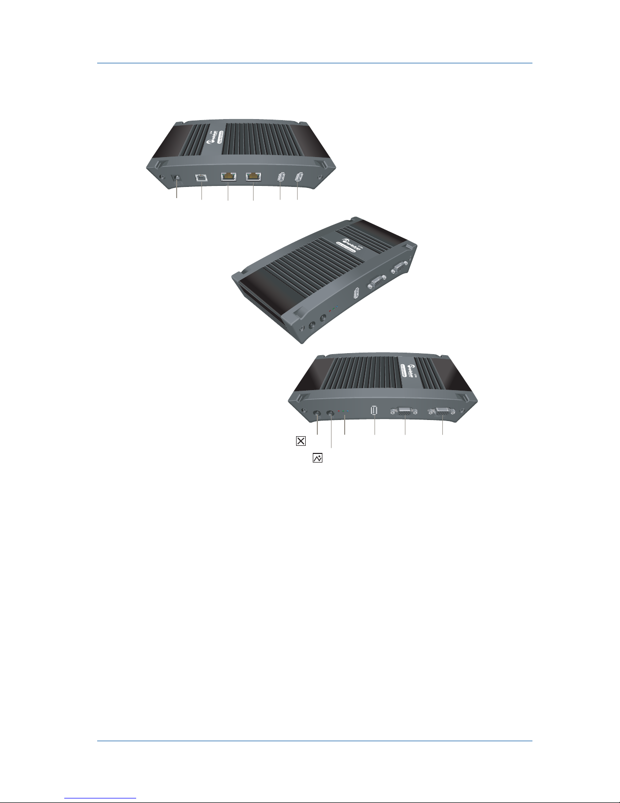
VGA Recorder Lite Hardware Features
The VGA Recorder Lite device is a 202mm × 105mm × 35mm
(7.95” × 4.13” × 1.38”) desktop unit. The left side panel includes 2
USB connectors, a power connector, and two Ethernet connectors.
The right side includes a reset button, LEDs, a USB connector, and
VGA out and VGA in connectors.
Red LED During operation the red LED blinks each time the
VGA Recorder records an image. You can use the
red LED as an indicator that the VGA Recorder is
recording images.
Reset
Button Reset the VGA Recorder Lite or Lecture Recorder
device to factory default settings. To use this
button, disconnect power to the device, press and
hold the Reset button as you reconnect the power.
The blue LED lights up. Keep pressing the Reset
button until the blue LED turns off and the Green
LED lights up. Release the Reset button. The device
starts normally but with all settings returned to
factory defaults.
Note: You may have to re-configure the device’s
network settings to reconnect the device to the
network. See the VGA Recorder User Guide for more
information.
Solid
State
Drive
Recordings made by the VGA Recorder Lite and
Lecture Recorder devices are saved to an internal
32 gigabyte solid state drive. The solid state drive
functions in the same way as the VGA Recorder
Standard and Pro internal hard disk. For simplicity
this document uses the term “hard disk” for the
internal storage available on all VGA Recorder
models.
1. Installation and Getting Started VGA Recorder Hardware Features
Install Guide Page 7
Figure 1: VGA Recorder Lite connectors and LEDs
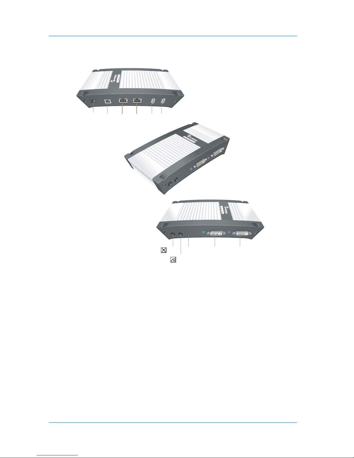
Lecture Recorder Hardware Features
The Lecture Recorder device is a 202mm × 105mm × 35mm (7.95”
× 4.13” × 1.38”) desktop unit. The left side panel includes 2 USB
connectors, a power connector, and two Ethernet connectors. The
right side includes a reset button, LEDs, a USB connector, and
OUTPUT and INPUT DVI and audio connectors.
Right Side
Reset
Button
Not
Used
LEDs VGA
OUT
VGA
IN
USB
USBUSBEth 2Eth 1Power
Left Side
Not
Used
1. Installation and Getting Started VGA Recorder Hardware Features
Page 8 VGA Recorder
Figure 2: Lecture Recorder connectors and LEDs
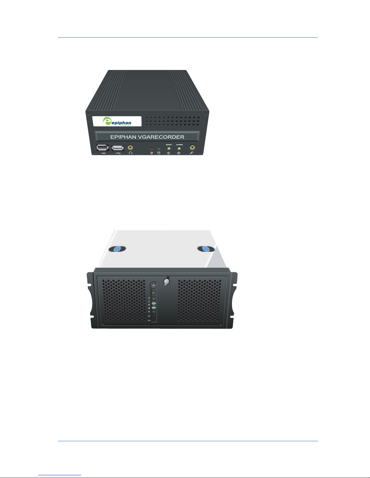
VGA Recorder Standard Hardware Features
The VGA Recorder Standard device is a 254 mm x 148 mm x
71 mm (10.0" x 5.8" x 2.8") standalone small form factor unit or 4U
rack-mount chassis. The front panel includes a USB connector,
power and hard disk activity LEDs, power and reset buttons, a
standard 3.5 mm microphone port, and a 3.5 mm headphone port.
The back panel includes Ethernet, VGA in, 3.5 mm unbalanced
stereo audio line in and power connectors.
Right Side
Reset
Button
Not
Used
LEDs OUTPUT INPUT
USBUSBEth 2Eth 1Power
Left Side
Not
Used
1. Installation and Getting Started VGA Recorder Hardware Features
Install Guide Page 9
Figure 3: VGA Recorder Standard front panel
VGA Recorder Pro Hardware Features
The VGA Recorder Pro device is a standalone 4U rack-mount
chassis. The front panel includes two USB connectors, power and
hard disk activity LEDs and power and reset buttons.
Figure 4: VGA Recorder Pro front panel
The back panel includes Ethernet, VGA in, 1/4-inch high quality
balanced audio line in, 3.5mm unbalanced stereo audio line in,
and power connectors.

1. Installation and Getting Started VGA Recorder Software Features
Page 10 VGA Recorder
VGA Recorder Software Features
Use the following software features, common to all VGA
Recorder models to install the VGA Recorder device on the
network.
Default IP
address and
network
mask
IP: 192.168.255.250
Netmask: 255.255.255.252
User Name: admin (no password)
IP address
from a
DHCP
server
The VGA Recorder device can get an IP address
on the network from a DHCP server if the
network has one. If the VGA Recorder gets an IP
address from a DHCP server, you can see the IP
address by running the Epiphan Network
Discovery Utility to find the VGA Recorder
device on the network. See “Using the Network
Discovery Utility to Find the IP Address of the
VGA Recorder Device” on page 22.
If the network does not have a DHCP server, see
the VGA Recorder User Guide.
Viewing and
working
with
recordings
Use the Web admin interface to start and stop
recording videos, and to view, rename,
download, and delete recorded videos. You can
log into the Web admin interface by selecting
Web config from the Epiphan Network
Discovery Utility or by opening a web browser
and browsing to:
http://<VGA Recorder_IP_Address>/admin/
User Name: admin (no password)
Using the Web admin interface to view and work
with recordings is described in the VGA Recorder
User Guide.

1. Installation and Getting Started Connect and Power on a VGA Recorder Lite Device
Install Guide Page 11
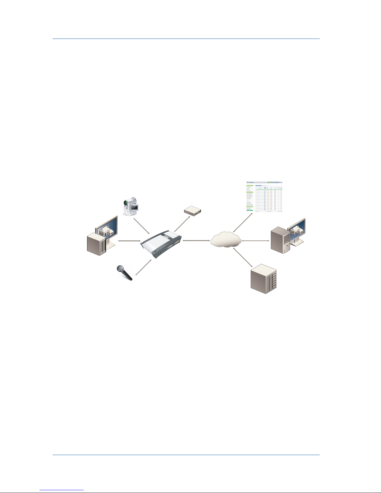
Connect and Power on a VGA Recorder
Lite Device
To connect a VGA Recorder Lite device you need:
•AVGAvideosource.
• An Ethernet connection between the VGA Recorder Lite
device and a network.
Figure 5: Connecting a VGA Recorder Lite device to an Ethernet
network and to other components
Web admin
interface Use the Web admin interface for changing the
VGA Recorder IP address, for configuring video
codec and Frame Grabber settings, to automate
uploading video files to a video repository, and
for other VGA Recorder configuration settings.
You can access the VGA Recorder configuration
settings by selecting Change Configuration from
the Web admin interface.
Using the Web admin interface to change the
VGA Recorder configuration is described in the
VGA Recorder User Guide.
Ethernet
Cable
VGA
Cable
Web Admin
Interface
VGA source
Ethernet
Network
VGA Recorder
Lite
Viewer or Administrator
Video Repository
(CIFS, rsync, FTP)
External USB
Storage Device
USB
1. Installation and Getting Started Connect and Power on a VGA Recorder Lite Device
Page 12 VGA Recorder
To connect and turn on the VGA Recorder Lite device
1Use a VGA cable to connect the VGA source to the VGA
Recorder Lite VGA IN port.
You can use an active VGA splitter to split the VGA signal
between a monitor and the VGA Recorder Lite device.
Note: Passive splitters reduce the quality of the VGA signal. Good
quality active splitters, (available from Epiphan) do not usually
affect signal quality. You should use a splitter with the highest
available bandwidth.
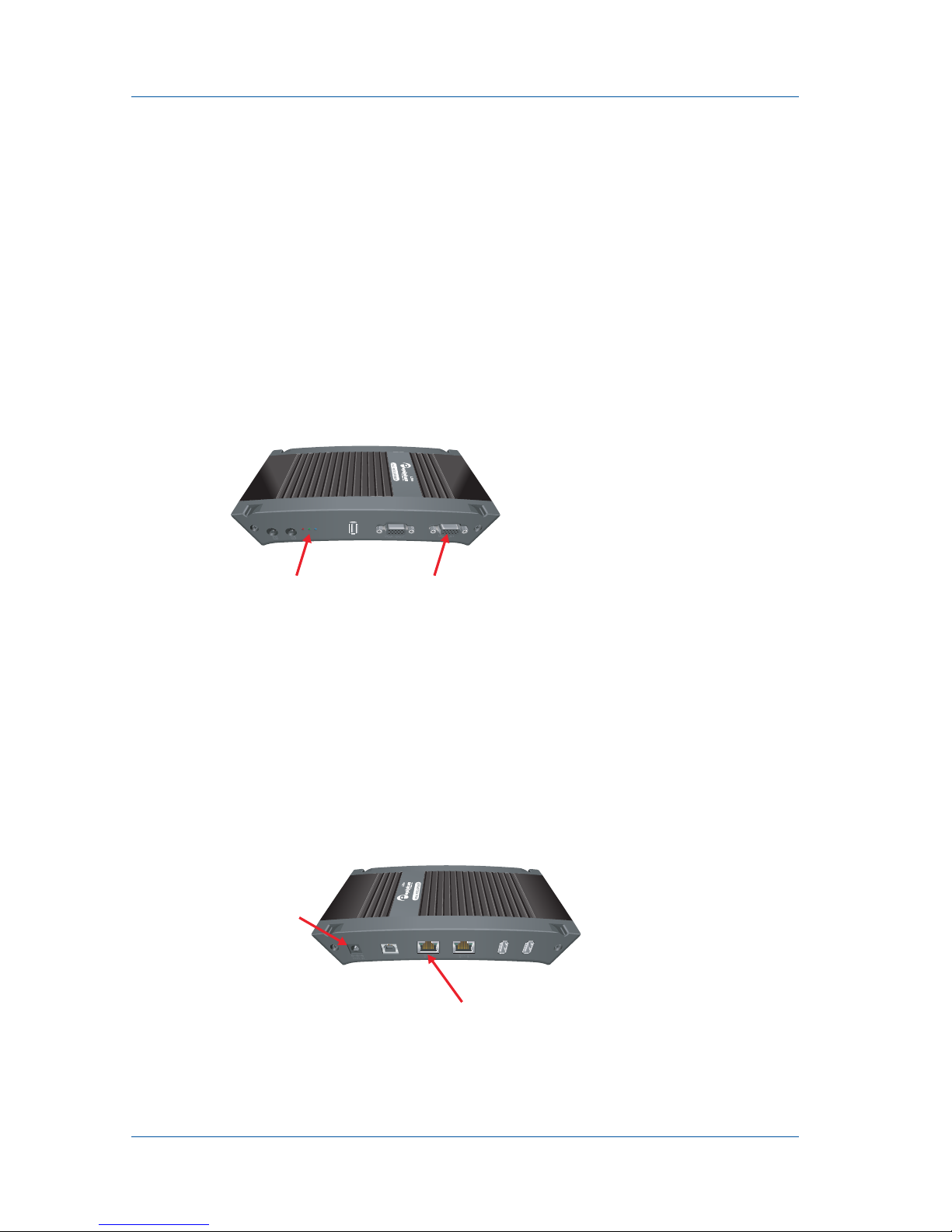
Figure 6: Connecting to a VGA source
2Use a RJ-45 Ethernet cable to connect the VGA Recorder Lite
Eth 1 port to your 10/100/1000 Base-T Ethernet network.
For best performance, connect the VGA Recorder Lite device
to a 1000 Base-T Ethernet. The network must be running the
TCP/IP protocol. Ideally the VGA Recorder
Lite device
should
be able to connect to the Internet.
3Connect the power adapter to the VGA Recorder Lite device.
Figure 7: Connecting to the Ethernet network and power
VGA INLEDs
Eth 1
Power Input

1. Installation and Getting Started Connect and Power on a VGA Recorder Lite Device
Install Guide Page 13
The VGA Recorder
Lite device
powers on and the LEDs go
through their power on sequence:
• When power is first connected the blue LED lights up.
• A few seconds later the green LED lights up.
• After about 20 seconds the blue LED turns off, leaving the
green LED on to indicate that VGA Recorder
device
has
started up and can start recording images.
4Start up the VGA source.
The Red LED should start flashing indicating that the
VGA
Recorder
Lite
device is recording images.
To confirm that the VGA Recorder Lite device is receiving
images from the VGA source:
• Check to see if the VGA Recorder Lite red LED is blinking
indicating that device is recording images.
If the red LED does not start flashing check the VGA source to
make sure it is transmitting a VGA image. Also check the cable
between the VGA Recorder
Lite device
and the VGA source to
make sure it is connected correctly. You can also connect a
monitor to VGA OUT to check for the presence of a signal.
5Log into the VGA Recorder Web admin interface
See “Connecting to the VGA Recorder Web admin interface”
on page 25.
1. Installation and Getting Started Connect and Power on a Lecture Recorder Device
Page 14 VGA Recorder
Connect and Power on a Lecture
Recorder Device
To connect a Lecture Recorder device you require:
• A VGA, DVI, or composite video source.
• An analog audio source (optional).
• An Ethernet connection between the Lecture Recorder Lite
device and a network.
Figure 8: Connecting a Lecture Recorder device to an Ethernet
network and to other components
To connect and turn on the Lecture Recorder device
1Connect the VGA, DVI, or composites video source to the
Lecture Recorder INPUT port using a VGA or DVI cable.
If you are connecting a VGA source, you require a VGA to
DVI converter. You can also use an active splitter to split the
VGA or DVI signal.
If you are connecting a composite video source, you require a
composite video to DVI adapter.
Ethernet
Cable
VGA or DVI
Cable
Web Admin
Interface
VGA or DVI source
Ethernet
Network
Lecture Recorder Viewer or Administrator
Video Repository
(CIFS, rsync, FTP)
External USB
Storage Device
USB
Composite
video
source
RCA composite
video cable
and adapter
Audio source
1. Installation and Getting Started Connect and Power on a Lecture Recorder Device
Install Guide Page 15
Note: Passive VGA or DVI splitters reduce the quality of the
video signal. Good quality active splitters, (available from
Epiphan) do not usually affect signal quality. You should use a
splitter with the highest available bandwidth.
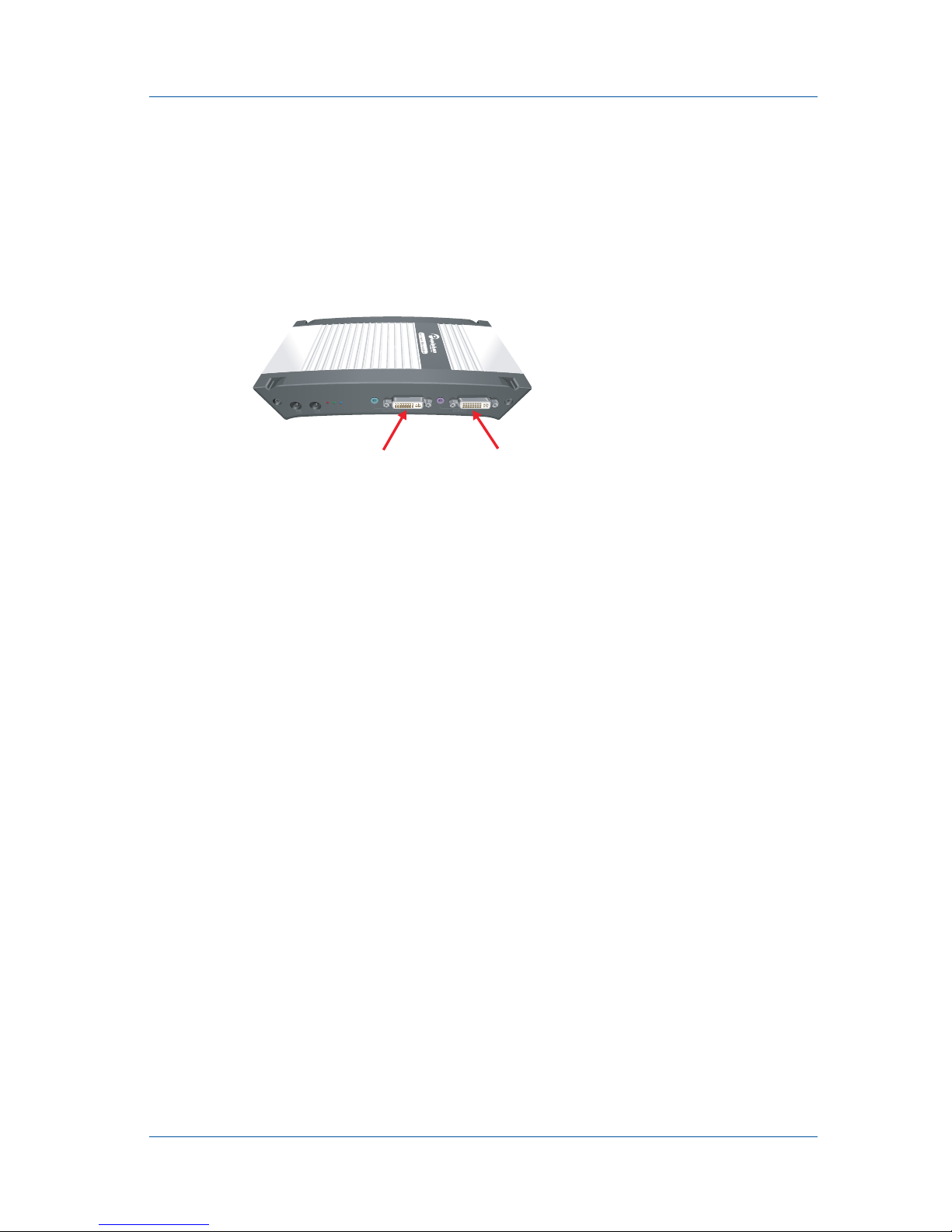
Figure 9: Location of Lecture Recorder INPUT and OUTPUT
ports
2You can also optionally connect a VGA or DVI monitor or
projector to the Lecture Recorder OUTPUT port to monitor
video as it is recorded.
If you are connecting a VGA monitor, you require a DVI to
VGA converter. You can also use an active splitter to split this
VGA or DVI signal.
3If you plan to record audio, connect an analog audio source to
the Lecture Recorder INPUT audio port.
You can also monitor the audio input by connecting an audio
amplifier to the OUTPUT audio port.
4Use a RJ-45 Ethernet cable to connect the Lecture Recorder
Eth 1 port to your 10/100/1000 Base-T Ethernet network.
For best performance, connect the Lecture Recorder device to
a 1000 Base-T Ethernet. The network must be running the
TCP/IP protocol. Ideally the
Lecture Recorder device
should
be able to connect to the Internet.
5Connect the power adapter to the Lecture Recorder device.
INPUTOUTPUT

1. Installation and Getting Started Connect and Power on a Lecture Recorder Device
Page 16 VGA Recorder
Figure 10:Connecting to the Ethernet network and connecting
power
The
Lecture Recorder device
powers on and the LEDs go
through their power on sequence:
• When power is first connected the blue LED lights up.
• A few seconds later the green LED lights up.
• After about 20 seconds the blue LED turns off, leaving the
green LED on to indicate that
Lecture Recorder device
has
started up and can start recording images.
6Start up the video source.
To confirm that the Lecture Recorder Lite device is receiving
images from the video source:
• Log into the VGA Recorder Web admin interface (see
“Connecting to the VGA Recorder Web admin interface”
on page 25) and confirm that a file is shown as recording.
• Under System Status select Start. If you cannot select Start,
the VGA Recorder is already recording.
• Select Preview to view the recorded image.
• Check to see if the Lecture Recorder red LED is blinking
indicating that device is recording images.
• If you connected a monitor to the OUTPUT port, check to
see if it displaying video.
If the red LED does not start flashing, and the monitor
connected to the OUTPUT port does not show an image, check
the video source to make sure it is transmitting a video image.
Also check the cable between the
Lecture Recorder device
and
the video source to make sure it is connected correctly.
Eth 1
Power Input

1. Installation and Getting Started Connect and Power on a VGA Recorder Standard Device
Install Guide Page 17
Connect and Power on a VGA Recorder
Standard Device
To connect a VGA Recorder Standard device you need:
•AVGAvideosource.
• An Ethernet connection between the VGA Recorder Standard
device and a network.
You can also connect:
• A 3.5 mm line in or microphone audio source
• Standard headphones to monitor audio.
Figure 11:Connecting a VGA Recorder Standard device to an
Ethernet network and to other components
To connect and turn on the VGA Recorder Standard device
1Use a VGA cable to connect the VGA source to the VGA
Recorder Standard VGA IN port on the back of the VGA
Recorder Standard device.
You can use an active VGA splitter to split the VGA signal
between a monitor and the VGA Recorder Standard device.
Audio source
(Microphone or
Line in)
Ethernet
Cable
Video Repository
(CIFS, rsync, FTP)
Web Admin
Interface
3.5 mm
Unbalanced
Audio
Ethernet
Network
VGA Recorder
Standard
External USB
Storage Device
USB
Viewer or Administrator
VGA
Cable
VGA or DVI-I
source

1. Installation and Getting Started Connect and Power on a VGA Recorder Standard Device
Page 18 VGA Recorder
Note: Passive splitters reduce the quality of the VGA signal. Good
quality active splitters, (available from Epiphan) do not usually
affect signal quality. You should use a splitter with the highest
available bandwidth.
2Use a RJ-45 Ethernet cable to connect the VGA Recorder
Standard Ethernet port on the back of the device to a
10/100/1000 Base-T Ethernet network.
For best performance, connect the VGA Recorder Standard
device to a 1000 Base-T Ethernet.
The network must be running the TCP/IP protocol. Ideally the
VGA Recorder
Standard device
should be able to connect to
the Internet.
3Connect the following optional components if you have them:
• Connect a 3.5 mm audio source to the Line in port on the
back of the VGA Recorder Standard device or connect a
microphone to the microphone port on the front of the
VGA Recorder Standard device. If you connect an audio
source you may have to change VGA Recorder Standard
audio settings. For example, if you connect a microphone
you must set the audio input source to Mic. See the VGA
Recorder User Guide for more information.
• Connect headphones to the headphone port on the front of
the VGA Recorder Standard device.
4Connect the power cable to the VGA Recorder Standard
device.
5Press the Power button on the VGA Recorder Standard front
panel to turn on the device.
The VGA Recorder
Standard device
powers on and the power
and hard disk activity LEDs light up as the device starts up:

1. Installation and Getting Started Connect and Power on a VGA Recorder Pro Device
Install Guide Page 19
6Start up the VGA source.
To confirm that the VGA Recorder Standard device is
receiving images from the VGA source connect a monitor to
VGA OUT to check for the presence of a signal.
If the monitor does not show an image, check the VGA source
to make sure it is transmitting a VGA image. Also check the
cable between the VGA Recorder
Standard device
and the
VGA source to make sure it is connected correctly.
7Log into the Web admin interface.
See “Connecting to the VGA Recorder Web admin interface”
on page 25.
Connect and Power on a VGA Recorder
Pro Device
To connect a VGA Recorder Pro device you need:
•AVGAvideosource.
• An Ethernet connection between the VGA Recorder Pro
device and a network.
You can also connect:
• A 1/4-inch high quality balanced audio source (line in) or a 3.5
mm line in audio source
• Standard headphones to monitor audio.
• A composite video source

1. Installation and Getting Started Connect and Power on a VGA Recorder Pro Device
Page 20 VGA Recorder
Figure 12:Connecting a VGA Recorder Pro device to an Ethernet
network and to other components
To connect and turn on the VGA Recorder Pro device
1Use a VGA cable to connect the VGA source to the VGA
Recorder Pro VGA IN port on the back of the VGA Recorder
Pro device.
You can use an active VGA splitter to split the VGA signal
between a monitor and the VGA Recorder Pro device.
Note: Passive splitters reduce the quality of the VGA signal. Good
quality active splitters, (available from Epiphan) do not usually
affect signal quality. You should use a splitter with the highest
available bandwidth.
2Use a RJ-45 Ethernet cable to connect the VGA Recorder Pro
Ethernet port on the back of the device to a 10/100/1000 Base-
T Ethernet network.
For best performance, connect the VGA Recorder Pro device to
a 1000 Base-T Ethernet.
The network must be running the TCP/IP protocol. Ideally the
VGA Recorder
Pro device
should be able to connect to the
Internet.
Ethernet
Cable
Video Repository
(CIFS, rsync, FTP)
Web Admin
Interface
Ethernet
Network
VGA Recorder
Pro
USB
Viewer or Administrator
Balanced or
Unbalanced
Audio
Composite
video
source
RCA composite
video cable
VGA
Cable
VGA or DVI -I
source
Audio source
(Line in)
External USB
Storage Device
This manual suits for next models
3
Table of contents
Other epiphan Recording Equipment manuals


