Pro-face GP-2401T User manual

User Manual
GP-2401/2501/2601 Series
(Pro-Designer Compatible)

1
GP-2401/2501/2601 Series User Manual
Thank you for purchasing the Pro-face GP-2401/2501/2601 Series programmable
operator interface (hereafter referred to as the “GP unit”).
GP-2401/2501/2601 Series units allow you to use the CF Card without attaching
separately sold expansion units.
Please read this manual carefully as it explains, step by step, how to use the GP
correctly and safely.
Also, in this manual’s examples, the Mitsubishi MELSEC-AnA Series PLC is
referred, whenever possible, as a point-to-point connection.
<Note>
1) It is forbidden to copy the contents of this manual, in whole or in part, except
for the user’s personal use, without the express permission of Digital Electron-
ics Corporation of Japan.
2) The information provided in this manual is subject to change without notice.
3) This manual has been written with care and attention to detail; however, should
you find any errors or omissions, please contact Digital Electronics Corporation
and inform them of your findings.
4) Please be aware that Digital Electronics Corporation shall not be held liable by
the user for any damages, losses, or third party claims arising from any uses of
this product.
All Company/Manufacturer names used in this manual are the registered trade-
marks of those companies.
© 2002 Digital Electronics Corporation
Preface

Preface
2GP-2401/2501/2601 Series User Manual
Preface........................................................................................................................ 1
Table of Contents...................................................................................................... 2
Essential Safety Precautions................................................................................... 4
General Safety Precautions .................................................................................... 8
GP-2401/2501/2601 Series Model Names............................................................ 10
Package Contents ................................................................................................... 10
UL/c-UL (CSA) Application Notes.................................................................... 11
CE Marking Notes ............................................................................................... 12
Revision Version ..................................................................................................... 13
Documentation Conventions................................................................................. 13
CHAPTER 1 INTRODUCTION
1.1 System Design...............................................................................................1-1
1.1.1 GP-2401/2501/2601 Series System Design.....................................1-1
1.2 Accessories ....................................................................................................1-3
CHAPTER 2 SPECIFICATIONS
2.1 General Specifications.................................................................................2-1
2.1.1 Electrical ............................................................................................2-1
2.1.2 Environmental....................................................................................2-2
2.1.3 Structural............................................................................................2-3
2.2 Functional Specifications............................................................................2-4
2.2.1 Display ...............................................................................................2-4
2.2.2 Memory ..............................................................................................2-4
2.2.3 Clock ..................................................................................................2-5
2.2.4 Interfaces........................................................................................... 2-5
2.3 Interface Specifications...............................................................................2-6
2.3.1 Serial Interfaces (COM1).................................................................. 2-6
2.4 Part Names and Functions .........................................................................2-8
2.5 Dimensions ..................................................................................................2-10
2.5.1 GP-2401T External Dimensions.....................................................2-10
2.5.2 GP-2501T External Dimensions..................................................... 2-11
2.5.3 GP-2601T External Dimensions.....................................................2-12
2.5.4 Panel Cut Dimensions.....................................................................2-13
2.5.5 Installation Fasteners.......................................................................2-13
Table of Contents

Preface
3
GP-2401/2501/2601 Series User Manual
CHAPTER 3 INSTALLATION AND WIRING
3.1 Installation ....................................................................................................3-1
3.1.1 Installation Procedures...................................................................... 3-1
3.2 Wiring Cautions...........................................................................................3-6
3.2.1 Connecting the Power Cord.............................................................. 3-6
3.2.2 Connecting the Power Supply ......................................................... 3-8
3.2.3 Grounding ..........................................................................................3-9
3.2.4 I/O Signal Line Placement ................................................................ 3-9
3.3 Tool Connector ...........................................................................................3-10
3.4 CF Card Installation and Removal......................................................... 3-11
3.4.1 CF card Handling ............................................................................3-13
3.5 Attaching the Screw Lock Terminal Block............................................3-14
CHAPTER 4 SETTINGS
4.1 Types of Settings ..........................................................................................4-1
4.1.1 Offline ................................................................................................4-3
4.1.2 System ................................................................................................4-5
CHAPTER 5 TROUBLESHOOTING
5.1 Troubleshooting Checklists ........................................................................5-1
5.1.1 No display .......................................................................................... 5-2
5.1.2 Connected devices cannot be used...................................................5-2
5.2 SELF TEST................................................................................................... 5-3
5.2.1 SELF TEST item list ......................................................................... 5-3
5.2.2 SELF TEST - details .........................................................................5-4
CHAPTER 6 MAINTENANCE
6.1 Regular Cleaning .........................................................................................6-1
6.1.1 Cleaning the Display ......................................................................... 6-1
6.1.2 Installation Gasket Check/Replacement ..........................................6-1
6.2 Periodic Check Points .................................................................................6-3
6.3 Replacing the Backlight..............................................................................6-4

Preface
4GP-2401/2501/2601 Series User Manual
This manual includes procedures that must be followed to operate the GP cor-
rectly and safely. Be sure to read this manual and any related materials thoroughly
to understand the correct operation and functions of this unit.
Safety Icons
Throughout this manual the following icons are provided next to GP operation
procedures requiring special attention, and provide essential safety information.
These icons indicate the following levels of danger:
Indicates situations where severe bodily
injury, death or major equipment damage
can occur.
Indicates situations where slight bodily
injury or machine damage can occur.
System Design
• Do not create GP touch panel switches that could possibly
endanger the safety of equipment and personnel. Damage
to the GP, its I/O unit(s), cable(s), and other related equip-
ment can cause an output signal to remain continuously
ON or OFF and possibly cause a major accident. There-
fore, design all monitoring circuits using limit switches,
etc. to detect incorrect device movement. To prevent acci-
dents related to incorrect signal output or operation, de-
sign all switches used to control vital machine operations
so they are operated via a separate control system.
• Please design your system so that equipment will not
malfunction due to a communication fault between the GP
and its host controller. This is to prevent any possibility of
bodily injury or material damage.
• Do not use the GP unit as a warning device for critical
alarms that can cause serious operator injury, machine
damage or production stoppage. Critical alarm indicators
and their control/activator units must be designed using
stand-alone hardware and/or mechanical interlocks.
• The GP is not appropriate for use with aircraft control
devices, aerospace equipment, central trunk data trans-
mission (communication) devices, nuclear power control
devices, or medical life support equipment, due to these
devices’ inherent requirements of extremely high levels of
safety and reliability.
Essential Safety Precautions
Caution
Warning
WARNINGS

Preface
5
GP-2401/2501/2601 Series User Manual
WARNINGS
• Do not create switches used to control machine safety
operations, such as an emergency stop switch, or a GP
touch screen icon. Be sure to install these switches as
separate hardware switches, otherwise severe bodily
injury or equipment damage can occur.
• When using the GP with : transportation vehicles (trains,
cars and ships), disaster and crime prevention devices,
various types of safety equipment, non-life support re-
lated medical devices, etc., redundant and/or failsafe sys-
tem designs should be used to ensure the proper degree
of reliability and safety.
Touch Panel
• After the GP’s backlight burns out, the touch panel is still
active. If the operator fails to notice that the backlight is
burned out and touches the panel, a potentially danger-
ous malfunction can occur.
If your GP’s backlight suddenly turns OFF, use the follow-
ing steps to determine if the backlight is actually burned out.
1) When the backlight burnout feature is not set, and
the screen has gone blank, your backlight is burned
out.
2) When the backlight burnout feature is set, and the
screen has gone blank, if touching the screen does
not cause the backlight to tourn ON, your backlight is
burned out.
It is recommended to use the feature that disables the
device operation to prevent accidental machine
misoperation when a backlight burnout is detected auto-
matically.
Wiring
• To prevent an electric shock, be sure to confirm that the
GP’s power cord is not connected to the main power
when connecting any cords, cables or lines to the GP.
• Be sure to replace the GP’s plastic terminal block cover
after wiring is completed, since operating the GP without
the cover may lead to an electric shock
• Do not use power beyond the GP’s specified voltage
range. Doing so may cause a fire or an electric shock.
Preface
6GP-2401/2501/2601 Series User Manual
Installation/Maintenance
• Be sure to securely connect all cable connectors to the GP.
A loose connection may cause incorrect input or output.
Battery Replacement
• The GP uses a lithium battery for backing up its internal
clock data. If the battery is incorrectly replaced, the bat-
tery may explode. To prevent this, please do not replace
the battery yourself. When the battery needs to be re-
placed, please contact your local GP distributor.
Installation/Maintenance
• High voltage runs through the GP. Except for replacing
the backlight, never take apart the GP, otherwise an elec-
trical shock can occur.
• Do not modify the GP unit. Doing so may cause a fire or
an electric shock.
• Do not use the GP in an environment where flammable
gasses are present, since operating the GP may cause an
explosion.
CAUTIONS
WARNINGS
Preface
7
GP-2401/2501/2601 Series User Manual
Wiring
• Ground the GP’s FG line separately from other units’ FG
lines. Putting these FG lines too close may cause an elec-
tric shock or unit malfunction. Be sure to use a grounding
resistance of 100ΩΩ
ΩΩ
Ωor less and a 2mm2or thicker wire, or
your country’s applicable standard.
• Be sure the GP’s rated voltage is within the designated
range, and that the power terminal lines are correctly
attached. If the voltage supplied differs from the rated
voltage, or incorrect wiring or grounding is performed, it
may cause a fire or unit malfunction.
• Use only the designated torque to tighten the GP’s termi-
nal block screws. If these screws are not tightened firmly,
it may cause a short-circuit, fire, or GP malfunction.
• Be careful that metal filings and wiring debris do not fall
inside the GP, since they can cause a fire, GP malfunc-
tion, or incorrect unit operation.
Display Device/CF Card
• The liquid crystal panel contains a powerful irritant and if
for any reason the panel is damaged and this liquid con-
tacts any part of your body, be sure to wash that area with
running water for 15 minutes. If any of this liquid enters
your eye, flush your eye for 15 minutes with running water
and contact a physician.
• Prior to inserting or removing a CF Card, be sure the CF
Card ACCESS lamp is not lit. If you do not, CF Card inter-
nal data may be damaged or lost.
• While a CF Card is being accessed, NEVER turn OFF or
reset the GP, or insert or remove the CF Card. Prior to
performing these operations, create and use a special GP
application screen that will prevent access to the CF
Card.
Unit Disposal
• When this unit is disposed of, it should be done so ac-
cording to your country’s regulations for similar types of
industrial waste.
CAUTIONS

Preface
8GP-2401/2501/2601 Series User Manual
General Safety Precautions
• Do not strike the touch panel with a hard or pointed object, or press
on the touch panel with too much force, since it may damage the
touch panel or the display.
• Do not install the GP where the ambient temperature can exceed the
allowed range. Doing so may cause the GP to malfunction or shorten
its operation life.
• Do not restrict or limit the GP’s naturally occurring rear-face ventila-
tion, or store or use the GP in an environment that is too hot.
• Do not use this unit in areas where large, sudden temperature
changes can occur. These changes can cause condensation to form
inside the unit., possibly causing the unit to malfunction.
• Do not allow water, liquids, metal or charged particles to enter inside
the GP’s case, since they can cause either a GP malfunction or an
electrical shock.
• Do not use or store the GP in direct sunlight, or in excessively dusty
or dirty environments.
• Do not store or use the unit where strong jolting or excessive vibra-
tion can occur.
• Do not store or use the GP where chemicals (such as organic sol-
vents, etc.) and acids can evaporate, or where chemicals and acids
are present in the air.
Corrosive chemicals: Acids, alkalines, liquids containing salt
Flammable chemicals: Organic Solvents
• Do not use paint thinner or organic solvents to clean the GP.
• Do not store or operate the LCD display in areas receiving direct
sunlight, since the sun’s UV rays may cause the LCD display’s qual-
ity to deteriorate.
• Storing this unit in areas at a temperature lower than is recommended
in this manual’s specifications may cause the LCD display’s liquid
to congeal, which may damage the panel. Conversely, if the storage
area’s temperature becomes higher than the allowed level, the LCD’s
liquid will become isotropic, causing irreversible damage to the LCD.
Therefore, be sure to store the panel only in areas where tempera-
tures are within those specified in this manual.
• Do not connect or disconnect the communication cable between the
GP and the host during power-ups.
• Due to the possibility of unexpected accidents, be sure to back up
the GP’s screen data regularly.

Preface
9
GP-2401/2501/2601 Series User Manual
About the GP’s Display Panel
• The GP’s currently displayed data, its voltage*1 and brightness set-
ting each affect the intensity of Contouring. (i.e, when some parts of
the screen are brighter than others, creating a wavelike pattern)
• There are minute grid-points (dark and light) on the Display Panel’s
surface. This is part of the GP’s design and not a defect.
• Extended shadows, or “Crosstalk” may appear on the sides of screen
images. This is normal for an LCD display.
• Sometimes the display area may look as if the display colors have
changed. This is a common attribute of LCD’s and is not a defect.
• Displaying a single image for long periods can cause an afterimage
to remain when the display is changed to another screen.
To prevent this effect:
Do not display any single screen for a long period of time. Try
to periodically change the screen display.
*1 If the GP’s voltage is at the very low end of its allowable range, it may effect the
intensity of contouring.
Preface
10 GP-2401/2501/2601 Series User Manual
The GP’s packing box contains the items listed below. Please check to confirm
that all items shown below have been included.
Package Contents
Installation Fasteners
(4/set) *1
Installation Guide (1)
This unit has been carefully packed, with special attention to quality. However,
should you find anything damaged or missing, please contact your local GP
distributor immediately for prompt service.
GP Unit (1)
GP2401-TC41-24V
GP2501-TC11
GP2501-SC11
GP2601-TC11 Installation
Guide
The GP-2401/2501/2601 Series refers to the following GP model numbers:
GP-2401/2501/2601 Series Model Names
*1 The shape of the supplied installation fastener may vary depending on the product
model. 2.5.5 Installation Fasteners
However, the mounting method is the same for every fastener.
Installation Gasket (1)
Model Name Model Type Comments
GP-2401
Series GP-2401T GP2401-TC41-24V UL/c-UL (CSA)
Approved,
CE Marked
GP-2501T GP2501-TC11
GP-2501S GP2501-SC11
GP-2601
Series GP-2601T GP2601-TC11 *1
GP2000
Series
Series
GP-2501
Series *1
*1 Revised models may or may not be listed as products conforming to UL/c-UL (CSA)
and CE Markings, depending on the revision version.
For information on how to determine the revision version, refer to
section “Revision Version” (page 13).
Preface
11
GP-2401/2501/2601 Series User Manual
UL/c-UL (CSA) Application Notes
The GP2401-TC41-24V is UL/c-UL (CSA) listed products. (UL file No.E182139)
The GP2501-TC11*1, GP2501-SC11*1, GP2601-TC11*1, are UL/c-UL (CSA) listed
products. (UL file No.E231702)
This unit conforms as a product to the following standards:
A) UL508 Industrial Control Equipment
B) UL60950 Safety Standard for Information Technology Equipment (3rd Edition,
issued December 1, 2001)
C) UL1604 Electrical Equipment for use in Class 1 & 2 - Division 2, or Class 3
Hazardous Locations.
D) CAN/CSA-C22.2, Nos. 142, and 213-M1987 Safety Standard for Information
Technology and Electrical Business Equipment
E) CAN/CSA-C22.2, No. 60950-00 Safety Standard for Information Technology
Equipment (3rd Edition, issued December 1, 2001)
F) CAN/CSA-C22.2, No. 213-M1987 Safety Standard for Information Technol-
ogy and Electrical Business Equipment
<Cautions>
• The GP must be used as a built-in component of an end-use product.
• The GP units must be used indoors only.
• This unit should be installed in the front face of a metal panel.
• If this unit is installed so as to cool itself naturally, be sure to install it in a
vertical panel. Also, be sure that the GP unit is mounted at least 100 mm away
from any adjacent structures or equipment. If these requirements are not met,
the heat generated by the GP unit’s internal components may cause the unit to
fail to meet UL/c-UL standard requirements.
• Make sure to set up a switch to turn off the power to the GP in an accessible
position on the end-use product that the GP unit is built-in. Make sure to
consider the current and voltage when selecting the switch.
• Make sure that the frame of the product to which the GP unit is built-in con-
forms to UL60950 standard requirements.
*1 The products on which Revision “3” is marked conform to the standard requirements.
For more information on how to determine the revision version, refer
to section “Revision Version” (page 13).
ABCDEF
GP2401-TC41-24V 3180034-01 {{{
GP2501-TC11*13180021-03 {{ {{
GP2501-SC11*13180021-04 {{ {{
GP2601-TC11*13180021-05 {{ {{
Model UL registered
format Standards

Preface
12 GP-2401/2501/2601 Series User Manual
CE Marking Notes
The GP2401-TC41-24V is CE marked products that conform to EMC directives
EN55011 Class A and EN61000-6-2.
The GP2501-TC11*1, GP2501-SC11*1 and GP2601-TC11*1are CE marked prod-
ucts that conform to EMC directives and the Low-voltage directive EN55011
Class A, EN61000-3-2, EN61000-3-3, EN61000-6-2 and EN60950.
For detailed CE marking information, please contact your local GP distributor.
UL1604 Conditions of Acceptability and Handling Cautions:
1. Power, input and output (I/O) wiring must be in accordance with Class I, Divi-
sion 2 wiring methods - Article 501- 4(b) of the National Electrical Code,
NFPA 70 within the United States, and in accordance with Section 18-152 of
the Canadian Electrical Code for units installed within Canada.
2. Suitable for use in Class I, Division 2, Groups A, B, C and D, Hazardous
Locations.
3. WARNING: Explosion hazard - substitution of components may impair suit-
ability for Class I, Division 2.
4. WARNING: Explosion hazard - when in hazardous locations, turn power OFF
before replacing or wiring modules.
5. WARNING: Explosion hazard - do not disconnect equipment unless power has
been switched OFF, or the area is known to be non-hazardous.
<Cautions>
• The GP must be used as a built-in component of an end-use product.
• The GP units must be used indoors only.
• This unit should be installed in the front face of a metal panel.
• If this unit is installed so as to cool itself naturally, be sure to install it in a
vertical panel. Also, be sure that the GP unit is mounted at least 100 mm away
from any adjacent structures or equipment. If these requirements are not met,
the heat generated by the GP unit’s internal components may cause the unit to
fail to meet the standard requirements.
• Make sure to set up a switch to turn off the power to the GP in an accessible
position on the end-use product that the GP unit is built-in. Make sure to
consider the current and voltage when selecting the switch.
• Make sure that the frame of the product to which the GP unit is built-in con-
forms to EN60950 standard requirements.
*1 The products on which Revision “3” is marked conform to the standard requirements.
For more information on how to determine the revision version, refer
to section “Revision Version” (page 13).
Preface
13
GP-2401/2501/2601 Series User Manual
The list below describes the documentation conventions used in this manual.
Documentation Conventions
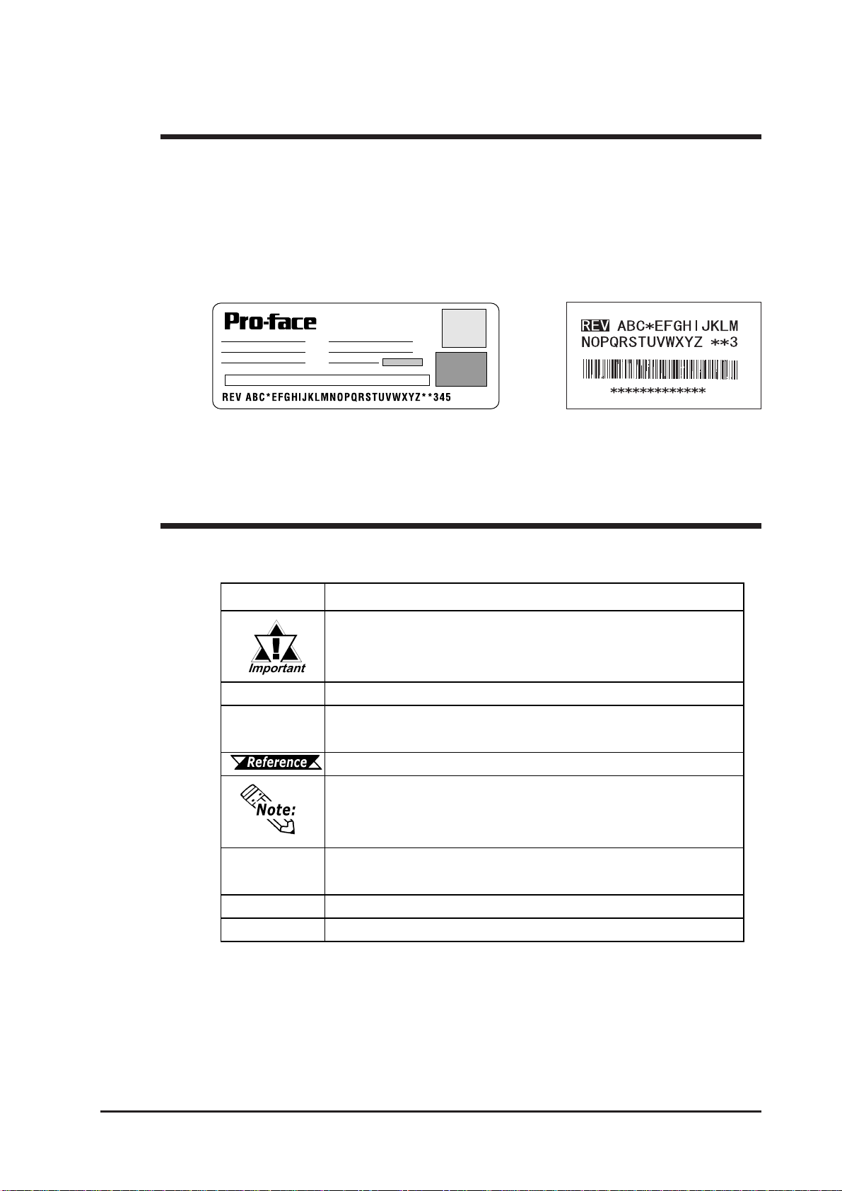
Revision Version
DIGITAL ELECTRONICS CORP.
The revision version can be determined by the identification label or revision
stickers that are placed on the main unit of the GP. The characters and numerals in
the “REV” area that are replaced with asterisks (*), or marked with a marker
indicate the revision version.
In the example below, the asterisks “*” are placed at positions “D”, “1”, and “2”,
which indicates the revision version as “D, 1, 2”.
Identification Label Revision Sticker
Symbol Description
Indicatesimportantinformationorproceduresthatmustbe followedfor
correctand risk-freesoftware/deviceoperation.
*1 Indicatesuseful orimportantsupplemental information.
1) , 2) Indicatesstepsinaprocedure.Besuretoperform thesestepsinthe
ordergiven.
Refersto usefulorimportantsupplemental information.
Providesuseful orimportantsupplementalinformation.
Screen
Editor Indicatesthe Pro-Designer(version4.0orhigher).
PLC Abbreviation forProgrammableLogic Controller.
n:1 Indicatesamulti-linktype connectionisused.

14 GP-2401/2501/2601 Series User Manual
Memo
1-1
GP-2401/2501/2601 Series User Manual
Chapter
1 Introduction
1. System Design
2. Accessories
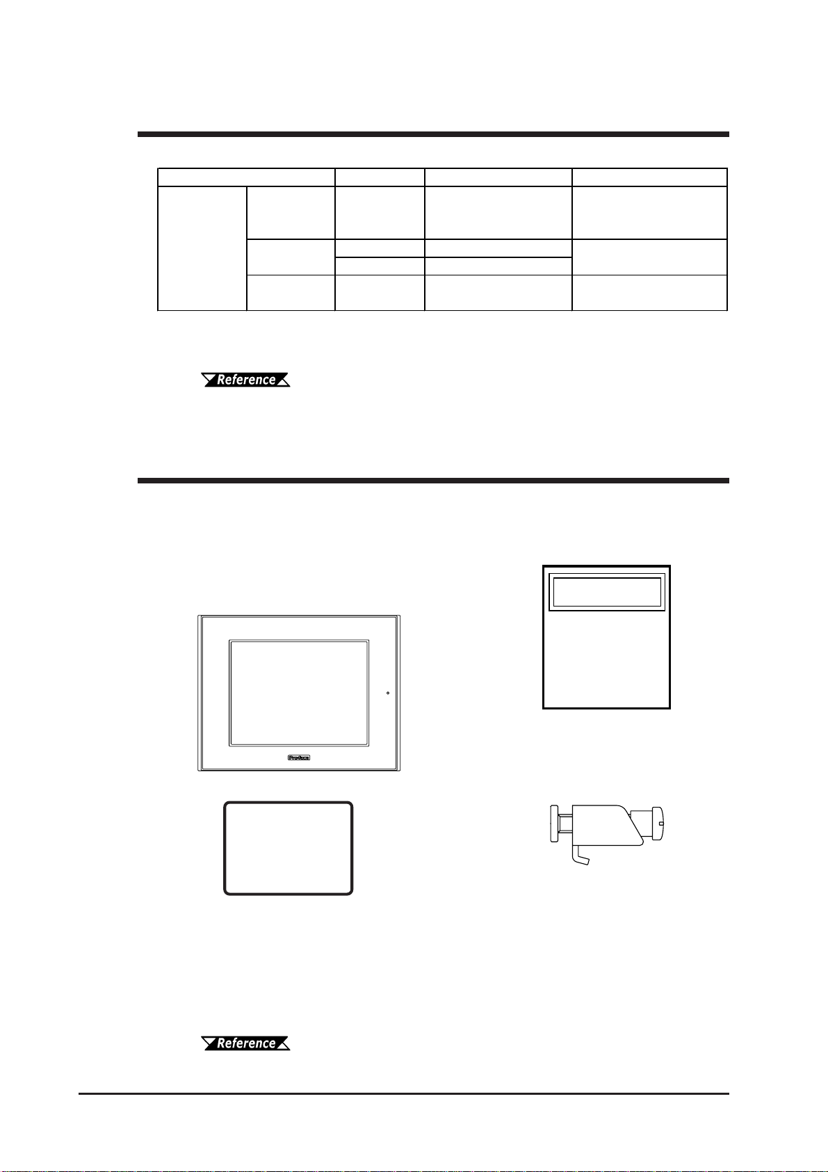
GP RUN Mode Peripherals
GP Unit
RS-232C Cable
GP410-IS00-O*1
CF Card
GP077-CF20,
GP077-CF30
RS-422 Cable
GP230-IS11-O*1
RS-422 Connector
Terminal Adapter
GP070-CN10-O*1
Mitsubishi PLC FX-Series
Program Port I/F Cable
GP430-IP11-O
Mitsubishi PLCA-Series
Program Port I/F Cable
GP430-IP10-O
Host Controller
Mitsubishi PLC A,
Q, C, FX Series’
2 Port Adapter II
GP070-MD11
PLC etc.
2 Port Adapter II
Cable
GP070-MDCB11
(2)
(3) (4)
(5)
(6)
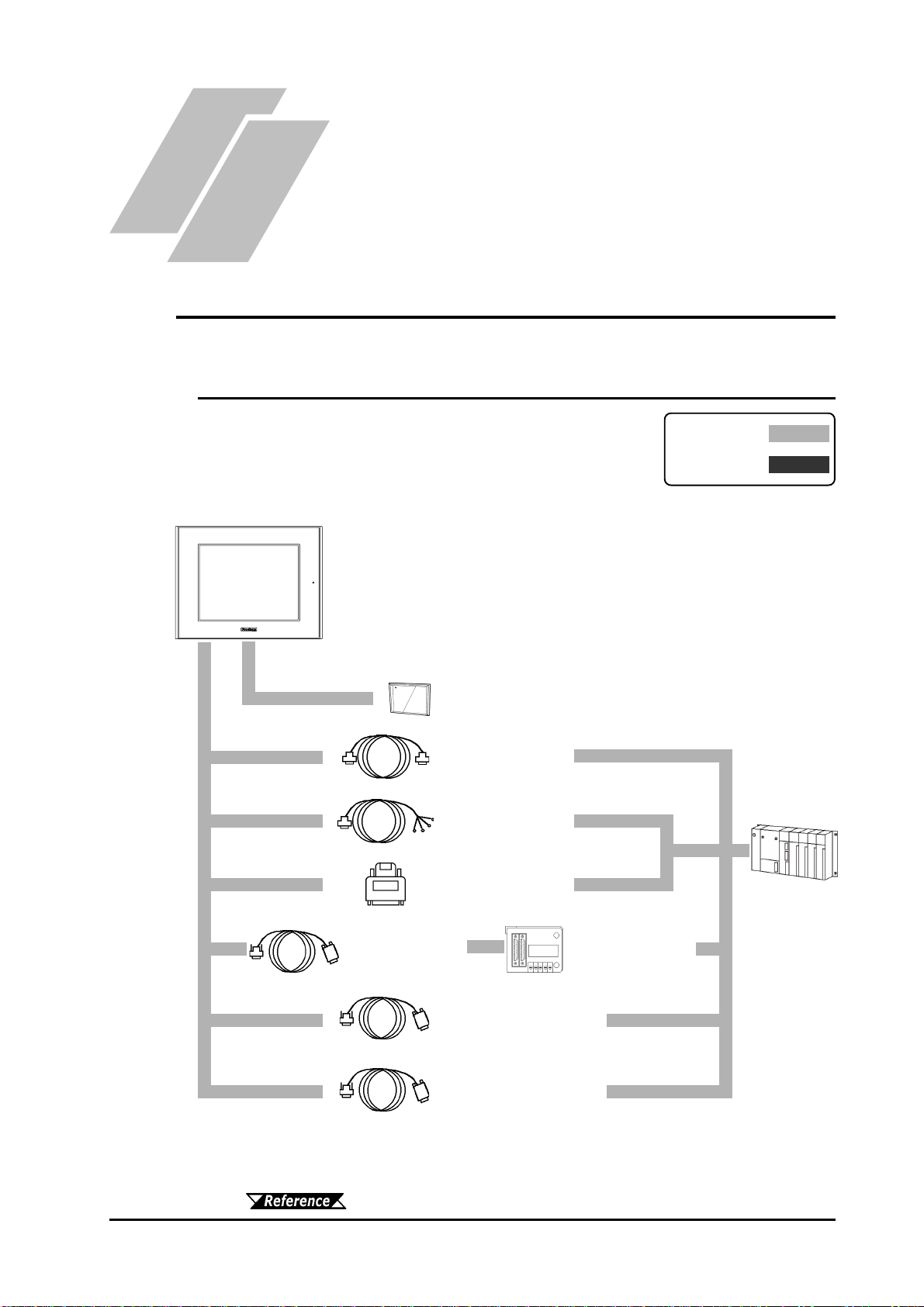
The following diagram represents the standard items connected to the GP.
1.1 System Design
1.1.1 GP-2401/2501/2601 Series System Design
(6)
(6)
Edit Mode
RUN Mode
*1 Certain types and models of PLCs cannot be connected.
Pro-Designer On-line Help
Chapter 1 - Introduction
1-2 GP-2401/2501/2601 Series User Manual
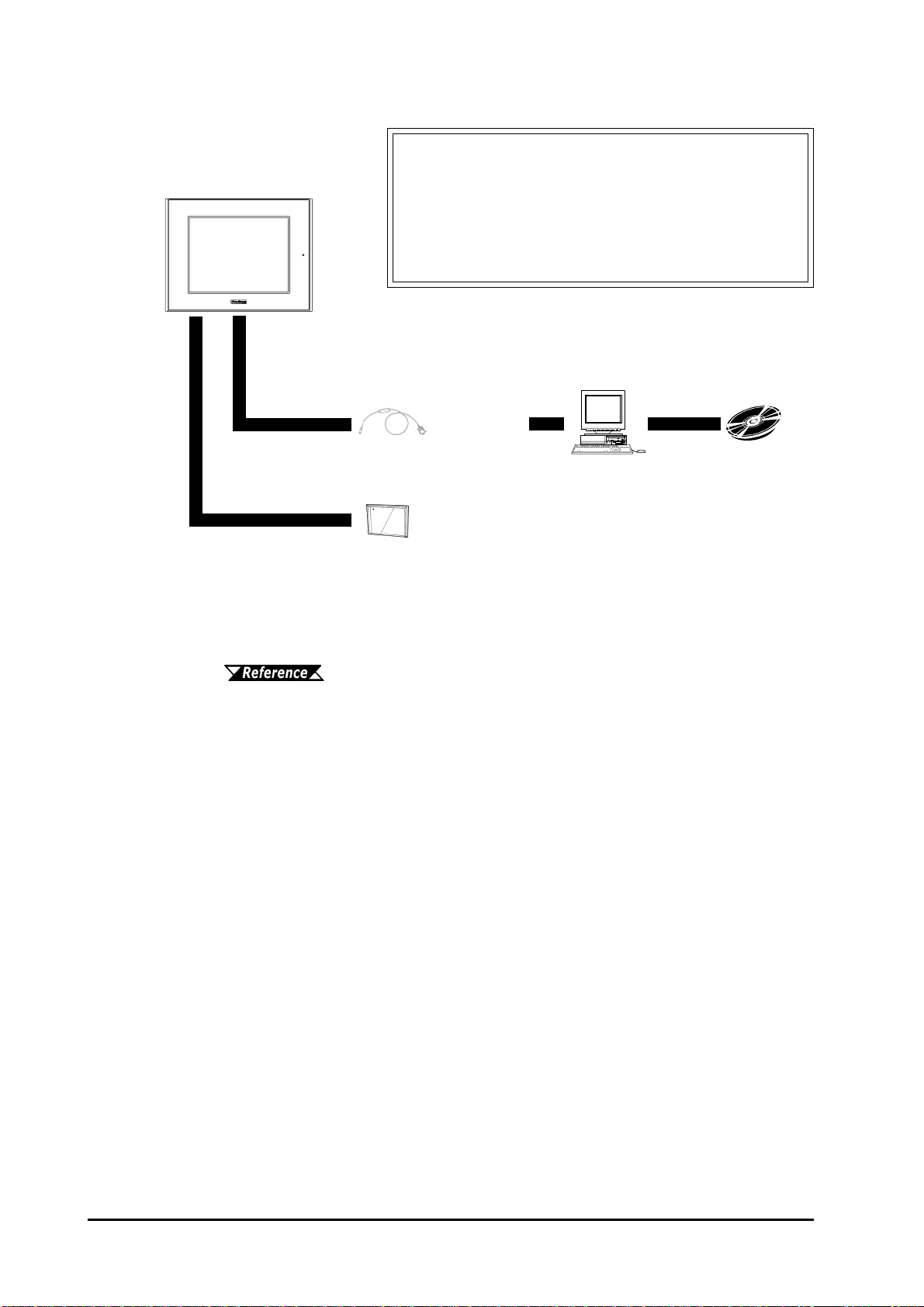
Data Transfer
Cable
GPW-CB02
GP Interfaces
(1)Tool Connector
(2)CF Card
(3)Serial Interface (COM1)
PLC Interfaces
(4)RS-232C Port
(5)RS-422 Port
(6)Programming Con-
sole Port
GP Edit Mode Peripherals
GP Unit
Personal
Computer *1 Pro-Designer
CF Card
GP077-CF20,
GP077-CF30
*1 Certain types and models of PCs cannot be connected.
Pro-Designer On-line Help
(1)
(2)

Chapter 1 - Introduction
1-3
GP-2401/2501/2601 Series User Manual
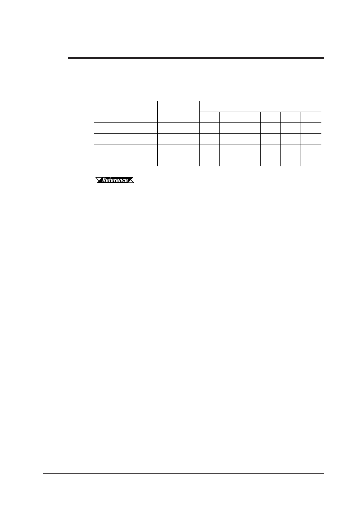
All optional equipment listed here is produced by Digital Electronics Corporation.
*1For detailed information about the range of connectable PLC manufacturers and
models,
Pro-Designer On-line Help
Available Software
Tool Connector
Serial Interfaces
1.2 Accessories
Product Name Model No. Description
Pro-Designer
Ver. 4.0 or later PS-DWE01-V40 Softwaretobe used tocreate thescreen
data.Installedina personalcomputer.
Product Name Model No. Description
RS-232C cable*1 GP410-IS00-O
RS-422 Connector
Terminal Adapter*1 GP070-CN10-O Conversionadapterto convertserialdata
toRS-422format
2 Port Adapter II GP070-MD11 Interfaceunitthatallowsuseofboth GP
andMitsubishi A,Q,CandFXseries
peripheralequipment.
2 Port Adapter II Cable GP070-MDCB11 ConnectstheGPto 2PortAdapterII.
Mitsubishi A Series
Programming Port I/F
cable GP430-IP10-O
Mitsubishi FX Series
Programming Port I/F
cable GP430-IP11-O
RS-422C cables*1 Interfacecablesbetweenthehost(PLC)
andtheGP.
Connectsdirectlyto Mitsubishi'sPLC
Programmingport.Simultaneoususeof
programmingconsole,however,isnot
possible.
GP230-IS11-O
Product Name Model No. Description
Screen Data
Transfer Cable GPW-CB02 ConnectstheGPto apersonalcomputer.
Transfersscreendataanduser
program(s).
Chapter 1 - Introduction
1-4 GP-2401/2501/2601 Series User Manual
Maintenance Items
They are available separately as optional maintenance items.
Screen Protection
Product Name Model No. Description
PS400-BU00-MS
(GP-2401T)
GP577RT-BL00-MS
(GP-2501T)
PS501S-BU00
(GP-2501S)
PS600-BU00
(GP-2601T)
Installation Fastener GP070-AT01 Fasteners to attach the GP to a panel.
(4fasteners/set)
PS400-WP00-MS
(GP-2401T)
GP570-WP10-MS
(GP-2501T/2501S/2601T)
Connector Cover PS-BH00 Attaches to GP rear face connectors.
(3/set)
Installation Gasket
Backlight ReplacementBacklight
Providesa moistureresistantsealwhen
installing the GP. Same asthe seal
includedintheGP'soriginalequipment
package.
CF Card Items
Product Name Model No. Description
CF Cards GP077-CF20 GPSeriesCF Card(16MB)
GP077-CF30 GPSeriesCF Card(32MB)
CF Card Adaptor GP077-CFAD10 CF Card AdapterforthePCMCIASlot.
Product Name Model No. Description
PSL-DF00
(GP-2501T,GP-2501S,
GP-2601T)
PS400-DF00(GP-2401T)
Screen Protection Sheet
Disposable,dirt-resistant sheet for the
GP'sscreen.TheGP'stouchpanelcan
beoperatedwiththiscoversheet
attached.(5sheets/set)

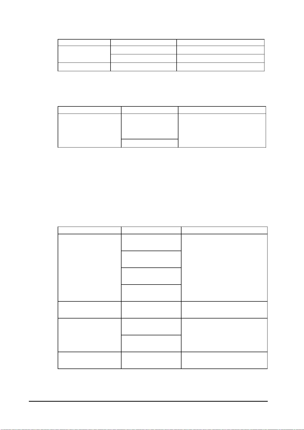
2-1
GP-2401/2501/2601 Series User Manual
2.1.1 Electrical
2.1 General Specifications
Chapter
2 Specifications
4. Part Names and Functions
5. Dimensions
1. General Specifications
2. Functional Specifications
3. Interface Specifications
GP2401-TC41-24V
GP2501-TC11/GP2501-SC11/GP2601-TC11
Input Voltage AC100V AC 100VtoAC240V*1
Rated Voltage AC85VtoAC132V AC85VtoAC265V*1
Power Consumption 50VAorless 50VAorless(ACIN100V)*1
85VAorless(ACIN240V)*1
Allowable Voltage Drop
Voltage Endurance
Insulation Resistance AC1500V20mAfor1minute (between chargingand FG terminals)
10MΩorhigheratDC500V(between chargingand FG terminals)
20msorless
*1 The products on which Revision “3” is marked conform to the standard requirements.
For more information on how to determine the revision version, refer
to section “Revision Version” (page 13).
Input Voltage
Rated Voltage
Power Consumption
Allowable Voltage Drop
In-rush Current
Voltage Endurance
Insulation Resistance
AC1000V20mAfor1minute
(betweenchargingandFG terminals)
10MΩorhigheratDC500V
(betweenchargingandFG terminals)
DC24V
DC19.2Vto DC28.8V
10msorless
30Aorless
28Worless
This manual suits for next models
7
Table of contents
Other Pro-face Recording Equipment manuals

Pro-face
Pro-face GP3000 Series User manual

Pro-face
Pro-face GP3000 Series User manual

Pro-face
Pro-face GP-4100 series User manual

Pro-face
Pro-face LT-4201TM User manual

Pro-face
Pro-face GP2000H Series User manual

Pro-face
Pro-face GP-4100 series User manual

Pro-face
Pro-face ST3200 Series User manual

Pro-face
Pro-face AGP-3300 Series User manual

Pro-face
Pro-face ST3200 Series User manual

Pro-face
Pro-face ST3000 Series User manual


