Epiq Solutions Matchstiq S1 Series Instructions for use

Matchstiq S1x Hardware User's Manual
Version 0.3

Disclaimer
Epiq Solutions is disclosing this document (“Documentation”) as a general guideline for
development. Epiq Solutions expressly disclaims any liability arising out of your use of the
Documentation. Epiq Solutions reserves the right at its sole discretion to change the
Documentation without notice at any time. Epiq Solutions assumes no obligation to correct
any errors contained in the Documentation or to advise you of any corrections or updates.
Epiq Solutions expressly disclaims any liability in connection with technical support or
assistance that may be provided to you in connection with the Information.
THE DOCUMENTATION IS DISCLOSED TO YOU “AS IS” WITH NO WARRANTY OF ANY
KIND. EPIQ SOLUTIONS MAKES NO OTHER WARRANTIES WHETHER EXPRESSED
IMPLIED OR STATUTORY REGARDING THE DOCUMENTATION INCLUDING ANY
WARRANTIES OF MERCHANTABILITY FITNESS FOR A PARTICULAR PURPOSE OR
NONINFRINGEMENT OF THIRD PARTY RIGHTS. IN NO EVENT WILL EPIQ SOLUTIONS
BE LIABLE FOR ANY CONSEQUENTIAL INDIRECT EXEMPLARY SPECIAL OR
INCIDENTAL DAMAGES INCLUDING ANY LOSS OF DATA OR LOST PROFITS ARISING
FROM YOUR USE OF THE DOCUMENTATION.
All material in this document is Copyrighted by Epiq Solutions 2015-2022. All trademarks are
property of their respective owners.
Matchstiq S1x Hardware User's Manual 2

Revision History
Date Revision Description
06/07/2018 0.1 -Initial draft
-Updated Matchstiq S10 H/W Users manual to also included S11 and S12
content
-Updated URLs and document hyperlinks
-Added Appendix A
01/03/2019 0.2 -Updated Figure 4
03/02/2022 0.3 -Updated Figure 3 added notes to section 7 updated Appendix A
Matchstiq S1x Hardware User's Manual 3

Table of Contents
1 About this Document .......................................................................................................................7
2 Legal Considerations ......................................................................................................................7
3 Proper Care and Handling ..............................................................................................................7
4 Introduction ..................................................................................................................................... 7
5 References .....................................................................................................................................8
6 Terms and Definitions .....................................................................................................................9
7 System Overview ..........................................................................................................................11
7.1 Externally Accessible I/O Ports ...............................................................................................13
7.2 Internally Accessible I/O Ports ................................................................................................15
7.3 Powering Up Matchstiq S1x ...................................................................................................16
7.4 Connecting Matchstiq S1x to a Host PC .................................................................................17
7.5 Executing Application .............................................................................................................18
7.6 Copying Files Between a Host PC and the Matchstiq Unit .....................................................19
8 RF Specifications ........................................................................................................................... 20
8.1 Matchstiq S12 Frequency Extension and Pre-Select Filtering ................................................21
9 Clock Specification .........................................................................................................................23
10 GPS Specification ........................................................................................................................23
11 Power Consumption .....................................................................................................................24
12 Understanding Data Transport on Matchstiq S1x .........................................................................25
12.1 Transporting Quadrature Baseband Samples between the RF Front End and the FPGA .....25
12.2 Transporting Data between the FPGA and Freescale i.MX6 CPU ........................................25
12.3 Transporting Data between the RJ45 Ethernet Interface and an External Ethernet Device . 26
13 Appendix A – Matchstiq S1x Statement of Volatility ......................................................................27
Matchstiq S1x Hardware User's Manual 4

Table of Figures
Figure 1: Matchstiq S10 system block diagram....................................................................................12
Figure 2: Matchstiq S11 system block diagram....................................................................................12
Figure 3: Matchstiq S12 system block diagram....................................................................................12
Figure 4: Matchstiq S1x front panel I/O................................................................................................13
Figure 5: Matchstiq S10 & S12 rear panel I/O......................................................................................14
Figure 6: Matchstiq S11 rear panel I/O................................................................................................15
Figure 7: S12 Frequency Extension & Filtering....................................................................................21
Figure 8: S12 High-Band Rx Pre-select Filter Frequency Response...................................................22
Figure 9: S12 Low-Band Rx Pre-select Filter Frequency Response....................................................22
Matchstiq S1x Hardware User's Manual 5

Table of Tables
Table 1: Terms and Definitions.............................................................................................................10
Table 2: RF Specifications...................................................................................................................20
Matchstiq S1x Hardware User's Manual 6

1 About this Document
This document provides an overview of the MatchstiqTM S1x SDR hardware platforms associated
capabilities and basic usage. It is provided with the purchase of a Matchstiq S1x unit.
2 Legal Considerations
Matchstiq is distributed all over the world. Each country has its own laws overnin
transmission and reception of radio frequencies. The user of the Matchstiq platform and
associated software is solely responsible for insurin that it is used in a manner consistent
with the laws of the jurisdiction in which it is used. Many countries, includin the United
States, prohibit the reception of certain frequency bands, or receivin certain transmissions
without proper authorization. A ain, the user is solely responsible for the user's own actions.
3 roper Care and Handling
The Matchstiq unit is fully tested by Epiq Solutions before shipment and is guaranteed functional at
the time it is received by the customer and ONLY AT THAT TIME. Improper use of the Matchstiq unit
can cause it to become non-functional. In particular a list of actions that may cause damage to the
hardware include the following:
•Opening up the unit while it is powered up
•Handling the unit without proper static precautions (ESD protection) when the housing is
removed or opened up
•Connecting a transmitter to the RX port without proper attenuation
•Executing custom software and/or an FPGA bitstream that was not developed according to
guidelines
The above list is not comprehensive and experience with the appropriate measures for handling
electronic devices is required.
4 Introduction
This guide provides an overview of the Matchstiq S1x SDR hardware platform associated capabilities
and basic usage. This includes the following:
•System level block diagram of the platforms
•Overview of the externally and internally accessible hardware ports
•Powering the system up and down
•Logging into a Matchstiq unit
•Executing applications on a Matchstiq unit
All documentation and support for Matchstiq S1x is provided through Epiq Solutions' support website
[2] which can be found at:
http s ://www.epiqsolutions.com/support
Note that there are separate product support forums for each of the different Matchstiq platform
variants available from Epiq Solutions including Matchstiq S1 Matchstiq Z1 and Matchstiq S1x / S2x.
Matchstiq S1x Hardware User's Manual 7

It is necessary to register prior to accessing the relevant information for your purchase.
5 References
[1] Epiq Solutions Main Website
http s ://www.epiqsolutions.com
[2] Epiq Solutions Support Website
http s ://www.epiqsolutions.com/support
[3] Epiq Solutions' Sidekiq MiniPCIe Card Product Pa e
https://www.epiqsolutions.com/sidekiq
[4] Gateworks Ventana GW5100 Product Pa e
http://www.gateworks.com/product/item/ventana-gw5100-network-processor
[5] Sidekiq FPGA Developer's Manual
https://epiqsolutions.com/support/viewforum.php?f=44
[6] Gateworks JTAG usa e wiki pa e
http://trac.gateworks.com/wiki/jtag_instructions
[7] Gateworks GPIO usa e wiki pa e
http://trac.gateworks.com/wiki/ventana/DigitalIO
[8] OpenWRT Linux distribution for Gateworks Ventana computer module wiki pa e
http://trac.gateworks.com/wiki/OpenWrt
[9] Wi2Wi W2SG0008i GPS receiver module datasheet
http://www.wi2wi.com/location-and-navigation/gps/w2sg0008i#documentation
[10] Gateworks GPS usa e wiki pa e
http://trac.gateworks.com/wiki/gps
[11] Gateworks OpenWRT + GPS wiki pa e
http://trac.gateworks.com/wiki/OpenWRT/GPS
Matchstiq S1x Hardware User's Manual 8

6 Terms and Definitions
Term Definition
1PPS 1 Pulse Per Second
A/D (ADC) Analog to Digital converter
AGC Automatic Gain Control
CPU Central Processing Unit
D/A (DAC) Digital to Analog converter
dB Decibel
dBm Decibels referenced to one milliwatt (mW)
DC Direct Current
DMA Direct Memory Access
ERA Epiq RF Analyzer
ESD ElectroStatic Discharge
FPGA Field Programmable Gate Array
GbE Gigabit Ethernet
GHz Gigahertz
GPS Global Positioning System
HDMI High Definition Multimedia Interface
I/O Input/Output
I/Q In-Phase / Quadrature Phase
JTAG Joint Test Action Group
kHz Kilohertz
LED Light Emitting Diode
LVDS Low-voltage Differential Signaling
MAC Media Access Control
MHz Megahertz
NMEA National Marine Electronic Association
OTG On-The-Go
PC Personal Computer
PDK Platform Development Kit
PoE Power over Ethernet
RF Radio Frequency
Rx Receive
SCP Secure CoPy
SDK Software Development Kit
Matchstiq S1x Hardware User's Manual 9

SDR Software Defined Radio
SLC Single-level cell (1 bit per cell)
SMA SubMiniature A (a style of RF connector)
SRFS System RF Server
SSH Secure SHell
TCVCXO Temperature Compensated Voltage Controlled Crystal Oscillator
Tx transmit
UART Universal Asynchronous Receiver Transmitter
uSD microSD
USB Universal Serial Bus
Table 1: Terms and Definitions
Matchstiq S1x Hardware User's Manual 10

7 System Overview
Matchstiq S1x are small form factor software defined radio transceivers that provide unprecedented
capability and flexibility while maintaining an aggressively low power consumption. Matchstiq S1x
combines Epiq Solutions' Sidekiq MiniPCIe card [3] with a custom variant of the Gateworks Ventana
GW5100 single board Linux computer module [4] to provide a complete software defined radio
platform. The features of the platform include the following:
Epiq Solutions' Sidekiq MiniPCIe Software Defined Radio Card
•Single RF transceiver covering 70 MHz to 6 GHz (S10/S11) and 1 MHz to 6 GHz (S12)
•Supports RF channel bandwidths up to 50 MHz
•Flexible gain controls to adapt to the current RF environment (both manual gain and AGC)
•Flexible clocking options to support symbol rate sampling at the A/D and D/A converters
•A/D sample rates up to 61.44 Msamples/sec (12-bits 'I' 12-bits 'Q')
•D/A sample rates up to 61.44 Msamples/sec (12-bits 'I' 12-bits 'Q')
•Xilinx Spartan 6 LX45T FPGA for signal processing and data transport to host Linux
computer module
•Supports x1 PCIe (Gen1.1 2.5 Gbps) and USB 2.0 high speed interface to host.
Gateworks Ventana GW5100 Linux Sin le Board Computer Module
•Freescale I.MX6 (quad-core ARM Cortex A9 CPU @ 800 MHz) running Linux
•2 GB of SLC Flash memory 1 GB of DDR3-800 RAM
•Integrated GPS receiver (Wi2Wi W2SG0008i based on SiRF Star IV chipset) with 1PPS
routed to Sidekiq
•RJ45 interface supporting 10/100/1000 Base-T Ethernet (supports Passive Power over
Ethernet)
•USB OTG (micro-B connector) interface for additional peripheral/connectivity options
•HDMI (micro-D connector) video output port
•Bi-color status LED
•Real-time clock with battery backup
•Run-time loadable/executable software applications
System
•Size: 4.41” x 1.65” x 1.13” (S10/S11) 4.41” x 2.00” x 1.43” (S12)
•Weight: 5.6 oz (S10/S11) 7.5 oz (S12)
•Typical power consumption: 5.5W (typical Rx only application 1000 Base-T Ethernet link)
•RF Interfaces (Tx antenna Rx antenna GPS antenna): SMA
•Power Input from 8V to 42V DC (via Lemo EGG.0B.302.CLL receptacle)
Matchstiq S1x Hardware User's Manual 11
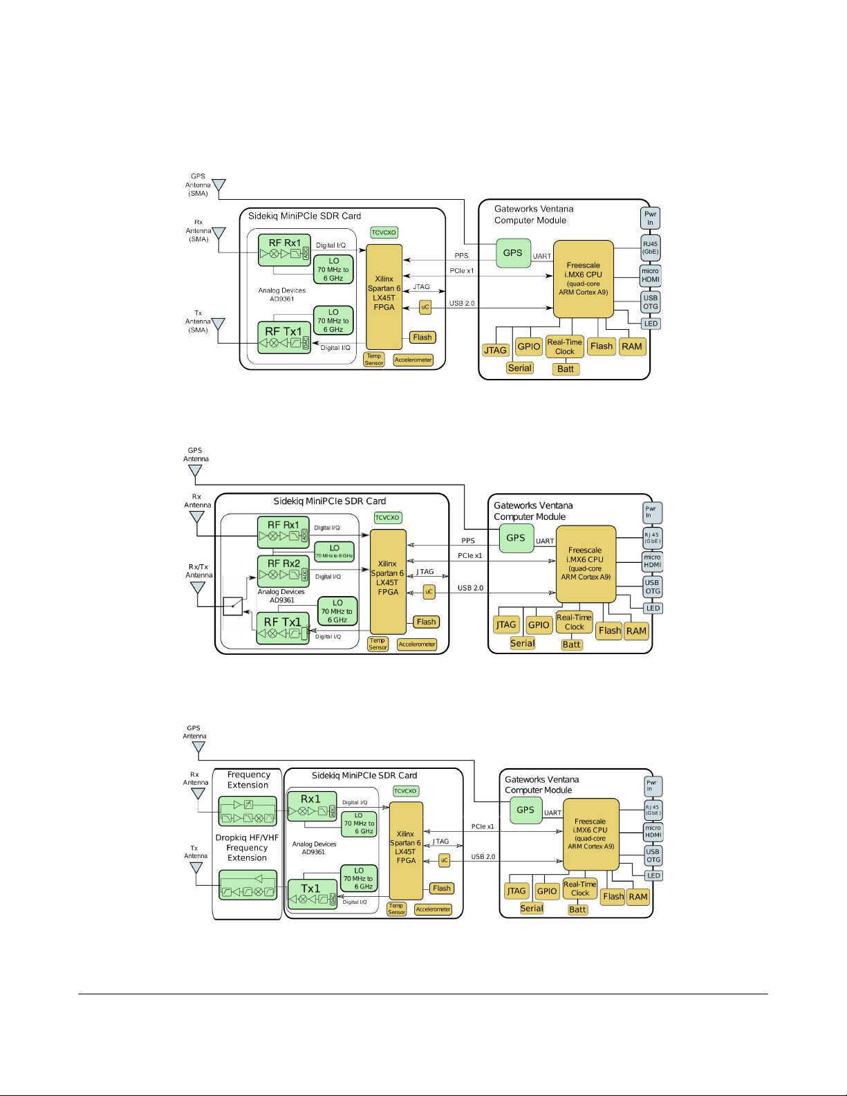
Block diagrams of the major sub-systems in the Matchstiq S1x units are shown in Figure 1 - 3.
Matchstiq S1x Hardware User's Manual 12
Figure 1: Matchstiq S10 system block diagram
Figure 2: Matchstiq S11 system block diagram
Figure 3: Matchstiq S12 system block diagram

Notes:
•1PPS support on Matchstiq S10/S11 requires custom FPGA bitstream
•1PPS and Fast-frequency hopping (FFH) are not supported on Matchstiq S12
7.1 Externally Accessible I/O Ports
Matchstiq S1x has user I/O ports on both the front panel and the rear panel of the unit. The front
panel of the unit contains the following ports:
•RJ45 Ethernet: This port is used to provide access to the 10/100/1000 Base-T Ethernet
interface. This is the primary interface used for connecting the unit to an external computer
network. This interface also supports passive Power over Ethernet allowing the Matchstiq S1x
unit to receive both power and Ethernet connectivity via a CAT5/6 Ethernet cable with the
appropriate power injector. Contact Epiq Solutions for details.
•DC Power Input: This port is used to provide input power to the platform. Input voltages
between 8V DC and 42V DC are supported. The input power receptacle is the Lemo
EGG.0B.302.CLL. The mating connector the Lemo FGG.0B.302.CLAD35Z can be found on
the AC/DC power adapter included with the Matchstiq S1x unit.
•Status LED: This dual-LED status LED is used to provide visual feedback to the user. This
LED includes both a green LED as well as a red LED. Both green and red LEDs can be turned
on simultaneously to provide an orange color.
Matchstiq S1x Hardware User's Manual 13
Figure : Matchstiq S1x front panel I/O

The rear panel of the unit also contains user I/O ports. This includes the following:
•Rx: This SMA port provides a 50 ohm interface to connect an external receive antenna to the
RF receiver. Note: The maximum safe RF input to this port without dama e is +20 dBm.
◦The Matchstiq S11 can operate as two phase coherent receivers (Rx1 & Rx2) or as 1 RX +
1 TX
•Tx: This SMA port provides a 50 ohm interface to connect an external transmit antenna to the
RF transmitter.
•GPS: This SMA port provides a 50 ohm interface to connect either a passive or active GPS
antenna for the internal GPS receiver. An active GPS antenna is recommended with a 3V DC
bias provided on the center pin. Note: The maximum safe RF input to this port without
dama e is +10 dBm.
•microUSB: This microUSB port provides a USB OTG port that can support operation as either
a USB host or a USB device. By default this port is configured for USB host mode and
provides 5V DC at 500 mA to power USB peripherals plugged in to this interface.
•microHDMI: This microHDMI interface port provides a video output interface through a
standard micro-D connector.
Matchstiq S1x Hardware User's Manual 14
Figure 5: Matchstiq S10 & S12 rear panel I/O

7.2 Internally Accessible I/O Ports
Matchstiq S1x also has several I/O ports that are only accessible on the inside of the unit due to the
limited front/rear panel space. These ports are enumerated below:
•JTAG for Xilinx Spartan 6 LX45T FPGA on Sidekiq: The JTAG port for the FPGA included
on Sidekiq is accessible via a special MiniPCIe extension cable that must be inserted in to the
MiniPCIe slot on the GW5100 computer module in place of Sidekiq. This extension cable then
routes to an external Sidekiq JTAG board where the Sidekiq MiniPCIe card is inserted. This
Sidekiq JTAG board provides access to standard JTAG programming headers. See the
Sidekiq FPGA Developer's Manual [5] for details regarding usage of the Sidekiq JTAG board
(the Sidekiq FPGA Developer's Manual is only available to customers who have purchased
either the Matchstiq S10 Platform Development Kit or the Sidekiq Platform Development Kit).
For details of accessing this internal port see Appendix A.
•JTAG for GW5100 Computer Module: The JTAG port for the GW5100 is available on a 2x5
pin header with designator J10 on the GW5100 computer module. This provides low level
access to the JTAG interface on the i.MX6 CPU as well as the 2GB flash device on the
GW5100. The appropriate JTAG adapter for connecting a PC to this JTAG interface
(Gateworks part # GW11033) is included in the Matchstiq S10 Software and Platform
Development Kits. The JTAG interface is accessed through a dedicated USB serial port
provided via the JTAG adapter and typically enumerates on a host Linux PC as /dev/ttyUSB0
(assuming no other USB serial port devices are plugged in to the host PC). Note: This JTAG
interface is not needed for standard usage. It is primarily used to perform recovery of the
GW5100 computer module in the event that it is required. For details of accessing this internal
port see Appendix A. For details of using the GW11033 JTAG adapter with the GW5100
computer module see [6].
Matchstiq S1x Hardware User's Manual 15
Figure 6: Matchstiq S11 rear panel I/O

•Serial Console for the GW5100 Computer Module: A standard serial console (UART) is
available on a 2x5 pin header with designator J10 on the GW5100 computer module. This is
the same header where JTAG can be found. The JTAG adapter [6] also provides access to
this serial console via the JTAG adapter's USB interface when connected to a host Linux PC.
This serial port typically enumerates on the host Linux PC as /dev/ttyUSB1 (assuming no other
USB serial port devices are plugged in to the host PC). The primary use of this serial console
is to allow access to the unit in cases where the Ethernet interface and the USB OTG interface
are not available. For details on accessing the serial console see [6].
•GPIO + UART Interfaces for the GW5100 Computer Module: There are four 3.3V GPIO
lines provided internally on the GW5100 computer module on a 2x5 pin header with designator
J11. These pins are connected directly to the i.MX6 CPU and can be accessed through Linux
user-space using the sysfs interface provided by default with the OpenWRT Linux distribution
installed on the GW5100. In addition this same header includes two 3.3V logic-level UARTs.
A 3.3V supply rail and GND rail are also provided. For details of using these GPIO signals
see [7] for details.
Note: For normal operation, it is not recommended to open up the Matchstiq S1x units in any
environment other than an ESD-safe environment. When openin up the Matchstiq S1x unit to
access these ports, it is imperative to exercise extreme care in handlin of the unit since the
internal electronic subsystems will be exposed.
7.3 Powering Up Matchsti S1x
Matchstiq automatically powers up whenever the appropriate Lemo power cable is plugged into the
power input receptacle on the unit. Once plugged in the complete Linux boot sequence automatically
begins. This sequence takes approximately 25 seconds to complete. The Ethernet network
initialization takes another ~15 seconds after booting is complete in order for the Ethernet interface to
be available for connection.
Note: The Status LED illuminates a solid green until the Linux kernel has fully booted (after
approximately 25 seconds) after which it defaults to a blinking green “heartbeat”.
Matchstiq S1x also supports passive Power over Ethernet (PoE) as a means to power the unit. In this
scenario power is supplied through the RJ45 Ethernet connector. Any input voltage between 8V DC
and 42V DC can be utilized through the PoE interface. The following guidelines should be used when
power is supplied through the RJ45 Ethernet connector:
•The positive input voltage is applied to pins 1-2 data pair and pins 4-5 data pair of the RJ45 cable.
•The negative input voltage is applied to pins 3-6 data pair and pins 7-8 data pair of the RJ45 cable.
•The positive inputs are all diode protected so that powering through one will not backfeed the
others.
•The RJ45 connector is rated for 0.6A maximum current per data pair for a total of 1.2A for both
data pairs.
•The RJ45 connector is not a hot plug connector and ALL CABLE CONNECTIONS SHOULD BE
MADE BEFORE POWER IS APPLIED.
Matchstiq S1x Hardware User's Manual 16

7.4 Connecting Matchsti S1x to a Host PC
Once the unit is powered up and the Linux kernel has booted the typical way to connect Matchstiq
S1x to a host PC is through the RJ45 Ethernet interface. This interface has a default static IP address
of 192.168.2.140. In order to connect to this interface from a host PC the host PC should have an IP
address on the same 192.168.2.xxx subnet (such as 192.168.2.1). The user should be able to ping
the Matchstiq S1x unit from a terminal shell on the host PC using the following command entered in to
the terminal shell:
$ ping 192.168.2.140
PING 192.168.2.140(192.168.2.140) 56(84) bytes of data.
64 bytes fro 192.168.2.140: ic p_req=1 ttl=64 ti e=0.323 s
64 bytes fro 192.168.2.140: ic p_req=2 ttl=64 ti e=0.390 s
64 bytes fro 192.168.2.140: ic p_req=3 ttl=64 ti e=0.225 s
64 bytes fro 192.168.2.140: ic p_req=4 ttl=64 ti e=0.405 s
64 bytes fro 192.168.2.140: ic p_req=5 ttl=64 ti e=0.343 s
--- 192.168.2.140 ping statistics ---
5 packets trans itted, 5 received, 0% packet loss, ti e 3999 s
rtt in/avg/ ax/ dev = 0.225/0.337/0.405/0.064 s
Another method of connecting the Matchstiq S1x to a host PC is through the USB OTG (micro-B
connector) interface. This interface has a default static IP address of 192.168.3.99.
$ ping 192.168.3.99
PING 192.168.3.99 (192.168.3.99) 56(84) bytes of data.
64 bytes fro 192.168.3.99: ic p_seq=1 ttl=64 ti e=0.306 s
64 bytes fro 192.168.3.99: ic p_seq=2 ttl=64 ti e=0.262 s
64 bytes fro 192.168.3.99: ic p_seq=3 ttl=64 ti e=0.239 s
64 bytes fro 192.168.3.99: ic p_seq=4 ttl=64 ti e=0.244 s
64 bytes fro 192.168.3.99: ic p_seq=5 ttl=64 ti e=0.247 s
--- 192.168.3.99 ping statistics ---
5 packets trans itted, 5 received, 0% packet loss, ti e 4086 s
rtt in/avg/ ax/ dev = 0.239/0.259/0.306/0.030 s
With a successful ping session complete network connectivity between the Matchstiq S1x and the
host PC has been confirmed. From here the user can proceed to establish a secure shell (SSH)
connection to the Matchstiq S1x unit from the host Linux PC. The default login credentials are:
username: root
password: root
Matchstiq S1x Hardware User's Manual 17

epiq@HostLinuxBox $ ssh [email protected]
[email protected]'s password:
=== Matchstiq S1x / S2x ===
=== Release 12.2 ===
root@OpenWrt-sn....:~#
Congratulations you have now established an SSH connection to the Matchstiq S1x unit and are
logged in. The default Linux distribution installed on Matchstiq S1x is called OpenWRT. This is a
popular Linux distribution typically used for embedded wireless routers and other networking devices.
Additional details of OpenWRT and its usage on the Gateworks GW5100 Ventana computer module
can be found in [8].
7.5 Executing Application
At power-up each Matchstiq unit can automatically launch a user's software application if desired.
Default application execution is provided by using the standard Linux init.d initialization scripts. For
example one possibility is to launch a software application by adding it to the /etc/init.d/rc.local script.
The SRFS (System RF Server) application is enabled by default at power-up on S1x units. You will
need to stop this service if you wish to run any of the test applications without a failure message.
To stop the srfs_rx service from running this power cycle: $ /etc/init.d/srfs_rx stop
Each Matchstiq unit ships with a set of test/validation applications that can be used to exercise
different functionality in the radio system. Matchstiq S1x can really be thought of as a small
embedded computer platform hosting Epiq Solutions' Sidekiq MiniPCIe SDR card. Thus the test
applications delivered on this platform are centered around demonstrating the functionality of Sidekiq.
The executable binaries for these test applications are all installed on the unit at
/root/sidekiq_image_current/test_apps/. The source code for these test applications are delivered as
part of the Software and Platform Development Kit along with the libsidekiq Linux userspace library. A
partial list of the utility applications shipped with each Matchstiq unit is shown below:
•rx_samples: an application for configuring the RF receiver and c/init.d/srfs_rx stoprecording
contiguous blocks of I/Q data to a file stored on the unit
•tx_samples: an application for configuring the RF transmitter and transmitting I/Q data that
has previously been stored in a file on the unit
•read_temp: a simple application for reading the current temperature of the unit
Matchstiq S1x Hardware User's Manual 18

These applications can be launched just like any normal Linux command line application would be
executed on the unit. The majority of the test apps explain their usage if the application is executed
without any command line arguments.
Note: The test apps contained in the Matchstiq S1x unit are intended to demonstrate usage of the
libsidekiq Linux userspace library and provide a basic starting point for users interested in developing
their own software applications using the SDK. These test apps are not intended to be full-featured or
optimized for execution.
7.6 Copying Files Between a Host PC and the Matchsti Unit
The simplest way to copy files to/from the Matchstiq unit is to use the secure copy or SCP command
line application. This is available by default in most major Linux distributions and a Windows version
called winscp is also available.
The syntax for copying a file from the host PC to the Matchstiq unit is:
$ scp <full path to file> root@<IP address of Matchstiq>:<full destination path on device>
For example to copy a file called “myapp” from the host PC to the root directory on a Matchstiq unit
with an IP address of 192.168.2.140 the following command would be used:
$ scp yapp [email protected]:/root/
Copying the myapp from the Matchstiq unit back to the host PC follows a similar command line only in
reverse:
Matchstiq S1x Hardware User's Manual 19

8 RF Specifications
Matchstiq S1x utilizes the Sidekiq SDR MiniPCIe card. Additional RF performance specifications for
this card can be found in the Sidekiq product spec sheet [2].
Matchstiq S10 S11 S12
Operating Modes One RF receiver and one RF
transmitter
One RF receiver and one RF
transmitter or as
Two phase coherent RF
receivers
One RF receiver and one RF
transmitter
Rx Pre-Select Filtering --- --- 7-band filters (sub-octave from
400MHz to 6 GHz)
RF Tuning Range 70 MHz to 6 GHz 70 MHz to 6 GHz 1 MHz to 6 GHz
RF Channel Bandwidth Up to 50 MHz Up to 50 MHz Up to 50 MHz
Typical Rx Noise Figure < 8dB < 8dB < 8dB
Typical Rx IIP3 -10 dBm -10 dBm -10 dBm
Rx Sample Rate Range 200 Ksamples/sec to 61.44
Msamples/sec
200 Ksamples/sec to 61.44
Msamples/sec
200 Ksamples/sec to 61.44
Msamples/sec
Tx Sample Rate Range 200 Ksamples/sec to 61.44
Msamples/sec
200 Ksamples/sec to 61.44
Msamples/sec
200 Ksamples/sec to 61.44
Msamples/sec
ADC & DAC sample width 12-bits 12-bits 12-bits
Rx Gain Range 0 - 76 dB 1dB steps 0 - 76 dB 1dB steps 0 - 76 dB 1dB steps
Tx Gain Range 0 to 89.75 dB 0.25 dB steps 0 to 89.75 dB 0.25 dB steps 0 to 89.75 dB 0.25 dB steps
Typical Tx Output Power +13 dBm < 2 GHz
+10 dBm > 2 GHz
+13 dBm < 2 GHz
+10 dBm > 2 GHz
+3 dBm Lowband (< 200MHz)
+13 dBm Highband (< 2GHz)
+10 dBm Highband (> 2 GHz)
Table 2: RF Specifications
Matchstiq S1x Hardware User's Manual 20
This manual suits for next models
6
Table of contents
Other Epiq Solutions Network Hardware manuals


Popular Network Hardware manuals by other brands


Dell
Dell P570 owner's manual
... Installation and configuration guide")
Cisco
Cisco Versatile Interface Processor (VIP6-80)... Installation and configuration guide

D-Link
D-Link DSM-G600 - MediaLounge Wireless G Network Storage Enclosure NAS... instruction manual

CORNING
CORNING EDGE 1U quick start guide

rialto
rialto WhiteBox installation manual

COBHAM
COBHAM OMU I user manual


