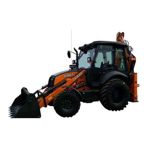
Epiroc EC 90T User manual

Instructions
Prefilling high pressure accumulator and piston accumulator
© Construction Tools GmbH | 3390 5140 01 | 2020-09-15
Original Instructions


Contents
© Construction Tools GmbH | 3390 5140 01 | 2020-09-15
Original Instructions
3
Table of Contents
1 About this Prefilling instruction ...............................................................................................4
2 Safety instructions.....................................................................................................................4
2.1 Signal words........................................................................................................................................................4
2.2 Qualification ........................................................................................................................................................5
2.3 Protective equipment..........................................................................................................................................5
2.4 Safety precautions ..............................................................................................................................................5
3 Prefilling......................................................................................................................................6
3.1 Prefilling the HP-accumulator............................................................................................................................6
3.1.1 Prefilling pressures for HP-accumulators ..........................................................................................................6
3.1.2 Filling procedure ................................................................................................................................................6
3.2 Prefilling the piston accumulator ......................................................................................................................8
3.2.1 Filling procedure ..............................................................................................................................................10
3.3 Bolt connections / Tightening torques ...........................................................................................................12
4 Appendix...................................................................................................................................13
4.1 Filling pressures for HP-accumulators (enlarged diagram)..........................................................................13

Instructions
4 © Construction Tools GmbH | 3390 5140 01 | 2020-09-15
Original Instructions
1 About this Prefilling
instruction
This Prefilling instruction describes how to prefill depres-
surised high pressure accumulators and piston accumu-
lators on hydraulic breakers
• EC 90T - EC 180T
• MB 750 - MB 1650
• HB 2000 - HB 10000
• C 135 - C 165
This Prefilling instruction complements your hydraulic
breaker's Safety and operating instructions in case of hy-
draulic breakers delivered in a depressurised state.
Follow all instructions in the Prefilling instruction and in
the Safety and operating instructions.
In this instruction, the high pressure accumulator of the
hydraulic breaker will be referred to by the abbreviation
HP-accumulator.
Store this Prefilling instruction in your workshop.
The different designation of the texts means as follows:
►
Action step in a safety instruction
♦
Action step
1.
2.
Established operation process
A
B
C
Explanation of the elements of a drawing
•
•
•
Listing
2 Safety instructions
This is the safety alert symbol. It is used to alert
you to potential personal injury hazards. Obey
all safety messages that follow this symbol to
avoid possible injury or death.
Read these Prefilling instruction and specifically
all safety instructions before starting to prefill.
This will:
• prevent the risk of injuries and fatal accidents for
yourself and others,
• protect the HP-accumulator, piston accumulator,
and other property against material damage,
• protect the environment against environmental dam-
age.
Follow all instructions in these Prefilling instruction.
2.1 Signal words
The signal words Danger, Warning, Caution, and Notice
are used as follows in this Prefilling instruction:
DANGER indicates a hazardous situation
which, if not avoided, will result in
death or serious injury.
WARNING indicates a hazardous situation
which, if not avoided, could result in
death or serious injury.
CAUTION indicates a hazardous situation
which, if not avoided, could result in
minor or moderate injury.
NOTICE The signal word NOTICE is used to
address practices related to possible
property damage but not related to
personal injury.

Instructions
© Construction Tools GmbH | 3390 5140 01 | 2020-09-15
Original Instructions
5
2.2 Qualification
As safety−relevant components, HP-accumulators are
subject to special safety regulations.
Prefilling HP-accumulators is only permitted if carried
out by professionals. Professionals are people who:
• are authorised to prefill HP-accumulators according
to the national regulations.
• know all the relevant national/regional safety provi-
sions and accident prevention rules,
• have read and understood this Prefilling instruction.
Prefilling piston accumulators is only permitted if car-
ried out by people who:
• know all the relevant national/regional safety provi-
sions and accident prevention rules,
• have read and understood this Prefilling instruction.
2.3 Protective equipment
Personal protective equipment must comply with the ap-
plicable health and safety regulations.
Always wear the following personal protective equip-
ment:
• safety glasses with side protectors
• protective gloves
• protective shoes
2.4 Safety precautions
DANGER Danger of suffocation
Increased concentration of nitrogen (N2) in breathable air
can cause shortness of breath. You can become immo-
bilized and unconscious.
uDo not breathe in concentrated nitrogen (N2).
uEffectively ventilate your workplace, if you prefill a
piston accumulator or HP-accumulator with concen-
trated nitrogen (N2).
DANGER Danger of explosions
The HP-accumulator and the piston accumulator of the
hydraulic breaker must be filled with nitrogen (N2). Filling
them with any other gas may trigger an explosion and
lead to serious, possibly fatal, injuries.
uOnly prefill the HP-accumulator and the piston accu-
mulator with nitrogen (N2).
uPrefill the HP-accumulator and the piston accumula-
tor in accordance with the national safety provisions.
WARNING Component coming loose abruptly /
Risk of bursting
The HP-accumulator may still contain compressed nitro-
gen. Opening HP-accumulators by force might loosen
components unexpectedly and cause injuries.
uOpening HP-accumulators by force, e.g. by sawing
them open etc., is strictly forbidden.

Instructions
6 © Construction Tools GmbH | 3390 5140 01 | 2020-09-15
Original Instructions
3 Prefilling
A hydraulic breaker with factory-made depressurised
HP-accumulator and piston accumulator is marked with
a corresponding label located on the hydraulic breaker's
hose connection.
Accumulators must be filled with nitrogen minimum class
4.0, ultra-clean, N2 99.9 vol.%.
nPlace the hydraulic breaker on a pallet or timber sup-
port blocks. The breaker box service opening must
be facing upwards.
nFollow the instructions to prefill a depressurised ac-
cumulator within an ambient temperature range of
-20°C to +40°C (-4°F to +104°F).
nAdjust to the correct pressure at operating tempera-
ture during commissioning.
nFollow all instructions in the Safety and operating in-
structions as well as the national/regional laws and
regulations valid in the country of use.
3.1 Prefilling the HP-accumulator
nPressurise the HP-accumulator in accordance with
the ambient temperature.
3.1.1 Prefilling pressures for HP-
accumulators
HP-accumulator 0.9l and 1.5l
50,0
55,0
60,0
65,0
-20 -10 0 +10 +20 +30 +40
y
x
x = Ambient temperature [°C]
y = Prefilling pressure [bar]
For better readability please refer to the enlarged version
of this diagram at the end of this Prefilling instruction.
3.1.2 Filling procedure
The following accessories can be supplied:
• 1 accumulator filling device with accessories, part
number 3360920415
From the available or supplied service box you will re-
quire:
• 1 nitrogen cylinder 2l, part number 3363034504
or
• 1 nitrogen cylinder 5l, part number 3363034506
• 1 pressure-relief valve, part number 3361329516
• 1 country-specific adapter, if required (see additional
document, document number 3390710601)
When filling the HP-accumulator, please observe the di-
agram above and follow the instructions provided step
by step.
N
O
P
Q SR
O
1. Remove the Allen screws(N) and the pairs of lock
washers(O).
2. Remove the plate(P) respectively the plates(P) from
the breaker box.
3. Remove the protective cap(S) from the HP-accumu-
lator's(Q) filler adapter(X).

Instructions
© Construction Tools GmbH | 3390 5140 01 | 2020-09-15
Original Instructions
7
E
C
D
R
X
B
M
L
F
H
I
J
K
Q
A
If a country-specific adapter(I) is required, it must be
installed between the nitrogen cylinder(J) and the
pressure relief valve(H).
4. Connect pressure-relief valve(H) to nitrogen cylin-
der(J).
5. Screw nipple(E) of connecting hose(M) to accumu-
lator filling device(B).
6. Slide filling device(B) onto filler adapter(X) of upper
shell and screw tight. (Please note: left-hand thread).
To this end the filler adapter(X) must be in lower po-
sition and the socket spanner(A) in upper position.
7. Attach connecting hose(M) to the minimess connec-
tion(L) of the pressure-relief valve(H).
8. Close bleed valve(C) on filling device.
9. Close check valve(F) on pressure-relief valve.
10.Open nitrogen cylinder valve(K) slowly.
11.Open check valve(F) on pressure-relief valve slowly
until required pressure corresponding to the ambient
temperature can be read on the pressure gauge(D)
of the filling device.
12.Once required pressure corresponding to the ambient
temperature has been attained, close check
valve(F).
WARNING Component coming loose abruptly
The HP-accumulator may contain compressed nitro-
gen. Unscrewing the filler screw(R) with screwdriver
might loosen the filler screw(R) unexpectedly and
cause injuries.
uOnly loosen the filler screw(R) with the socket
spanner(A) of the filling device(B).
13.Using socket spanner(A), screw out filler screw(R)
as far as it will go.
14.Open check valve(F) on pressure-relief valve slowly
until required pressure can be read on the pressure
gauge(D) of the filling device.
15.Once required pressure has been attained, close
check valve(F).
16.Wait for temperature in accumulator to balance.
17.If pressure gauge reading is now too high, reduce
pressure using bleed valve(C).
18.If reading is too low, top up gas pressure.
19.If accumulator pressure reading is correct, tighten
filler screw(R) firmly using socket spanner(A).
20.Close nitrogen cylinder valve(K).
21.Depressurise connecting hose using bleed valve(C)
and remove filling device.
22.Fit the protective cap(S) to the filler adapter(X).
23.Remove the label "Depressurised high pressure ac-
cumulator and piston accumulator" from the hydraulic
breaker's hose connection.
24.Fit the plate(P) respectively the plates(P) with Allen
screws(N) and pairs of lock washers(O) to the
breaker box, if you do not need to prefill the piston
accumulator as well. Tighten Allen screws to the
torque required (see chapter Bolt connections /
Tightening torques).

Instructions
8 © Construction Tools GmbH | 3390 5140 01 | 2020-09-15
Original Instructions
3.2 Prefilling the piston accumulator
nSelect the hydraulic breaker type (columnA) to be prefilled with nitrogen.
nPressurise the piston accumulator to the prefilling pressure (columnB).
Prefilling pressures and needed gas according to the relevant hydraulic breakers
ABCDE
Hydraulic breaker
type
Prefilling pressure
with an ambient tem-
perature range of
-20°C to +40°C
Required quantity of
gas for prefilling of
HPaccumulator only
Required quantity of
gas for prefilling of
piston accumulator
only
Required quantity of
gas for prefilling of
piston accumulator
and HPaccumulator
[bar] [litre x bar] [litre x bar] [litre x bar]
EC 90T 10.4 0 21 21
EC 100T 6.7 0 15 15
EC 120T 6.7 0 24 24
EC 135T 5.5 0 26 26
EC 140T 6.6 54 34 88
EC 150T 10.2 54 61 115
EC 155T 11.4 54 73 127
EC 165T 12.0 90 99 189
EC 180T 9.1 90 104 194
MB 750 8.1 0 14 19
MB1000 5.0 0 12 12
MB 1200 9.3 0 36 36
MB 1500 8.2 0 39 39
MB 1650 8.9 0 47 47
MB 1700 8.0 54 41 95
HB 2000 10.4 54 59 113
HB 2500 9.8 54 63 117
HB 3100 12.0 90 100 190
HB 3600 9.7 90 90 180
HB 4100 9.8 90 101 191
HB 4700 8.8 90 115 205
HB 5800 7.9 90 113 203
HB 7000 7.5 180 148 328
HB 10000 7.5 180 206 386
C 135 8.1 0 29 29
C 140 6.6 0 31 31
C 165 9.7 90 80 170

Instructions
© Construction Tools GmbH | 3390 5140 01 | 2020-09-15
Original Instructions
9
Calculation of nitrogen quantity
nSelect the hydraulic breaker type (columnA) to be prefilled with nitrogen.
nFor prefilling the HP-accumulator only, multiply the required gas amount (columnC) with the quantity of hydraulic
breakers to be prefilled.
nFor prefilling the piston accumulator only, multiply the required gas amount (columnD) with the quantity of hy-
draulic breakers to be prefilled.
nFor prefilling both HP-accumulator and piston accumulator multiply the required gas amount (columnE) with the
quantity of hydraulic breakers to be prefilled.
Required quantity of nitrogen cylinders = [(pressure x capacity) of nitrogen cylinder] ÷ [(required gas amount x quantity)
of hydraulic breaker type]

Instructions
10 © Construction Tools GmbH | 3390 5140 01 | 2020-09-15
Original Instructions
3.2.1 Filling procedure
The following accessories can be supplied:
• 1 filling valve with pressure gauge 0-100bar, part
number 3361329516
• 1 filling hose 700mm length, part number
3361329517
or
• 1 filling hose 4000mm length, part number
3360479259
• 1 test pressure gauge ¼", 0-25bar, test category
1.6, part number 3361329518
• 1 nitrogen cylinder 2l, part number 3363034504
or
• 1 nitrogen cylinder 5l, part number 3363034506
• 1 country-specific adapter, if required (see additional
document, document number 3390710601)
The piston accumulator must to be filled through the fill-
ing valve. The filling valve is marked with »G« on the
cylinder cover. When filling the piston accumulator,
please observe the table above and follow the instruc-
tions provided step by step.
N
O
P
GO T
When the plate respectively the plates have not yet been
removed:
nRemove the Allen screws(N) and the pairs of lock
washers(O).
nRemove the plate(P) respectively the plates(P) from
the breaker box.
If a country-specific adapter(I) is required, it must be in-
stalled between the nitrogen cylinder and the pressure
relief valve(H).
T
U
F
H
I
K J
V
G
L
V
G
1. Connect the pressure relief valve(H) to the nitrogen
cylinder(J).
2. Close the check valve(F) on the pressure relief
valve(H).
3. Connect the filling hose end(V) to the minimess con-
nection(L) of the pressure relief valve.
4. Open the valve(K) of the nitrogen cylinder.
5. Remove the threaded plug(T) from the filling
valve(G).
6. Push the free filling hose end(V) onto the filling
valve(G).
7. Slowly open the check valve(F) on the pressure re-
lief valve to let the nitrogen flow into the piston accu-
mulator.
8. Read out the pressure increase from the pressure
gauge(U).
9. Close the check valve(F) on the pressure relief valve
when the piston accumulator has reached the re-
quired prefill pressure +10%.
10.Pull the filling hose out of the filling valve(G).
11.Check the pressure in the piston accumulator and let
gas escape until the required gas pressure has been
reached.
12.Install the threaded plug(T) in the filling valve(G)
and tighten it to the required tightening torque (see
chapter Bolt connections / Tightening torques).
13.Close the nitrogen cylinder valve(K).
14.Remove the label "Depressurised high pressure ac-
cumulator and piston accumulator" from the hydraulic
breaker's hose connection.

Instructions
© Construction Tools GmbH | 3390 5140 01 | 2020-09-15
Original Instructions
11
15.Fit the plate(P) respectively the plates(P) with Allen
screws(N) and pairs of lock washers(O) to the
breaker box. Tighten Allen screws to the torque re-
quired (see chapter Bolt connections / Tightening
torques).
16.Adjust to the correct pressure at operating tempera-
ture during commissioning.

Instructions
12 © Construction Tools GmbH | 3390 5140 01 | 2020-09-15
Original Instructions
3.3 Bolt connections / Tightening torques
Description Key size Tightening torque
Piston accumulator filling valve »G«
(threaded plug)
5 20 Nm (15 ft lbs)
Service opening plate
(Allen screw)
10 85 Nm (63 ft lbs)

Instructions
© Construction Tools GmbH | 3390 5140 01 | 2020-09-15
Original Instructions
13
4 Appendix
4.1 Filling pressures for HP-accumulators (enlarged diagram)
HP-accumulator 0.9l and 1.5l
50.0
55.0
60.0
65.0
-20 -10 0 +10 +20 +30 +40
y
x
x = Ambient temperature [°C]
y = Prefilling pressure [bar]


epiroc.com
© Construction Tools GmbH | 3390 5140 01 | 2020-09-15
Any unauthorized use or copying of the contents or any part thereof is prohibited. This
applies in particular to trademarks, model denominations, part numbers, and drawings.
This manual suits for next models
7
Table of contents
Other Epiroc Construction Equipment manuals
Epiroc
Epiroc Flexi ROC T20 R Instructions for use
Epiroc
Epiroc HC Series Maintenance and service guide

Epiroc
Epiroc Secoroc COP 44 Specifications
Epiroc
Epiroc SBU 160 Maintenance and service guide
Epiroc
Epiroc DEQ171257 User manual
Epiroc
Epiroc SmartROC T35 User manual
Epiroc
Epiroc EC Series Maintenance and service guide
Epiroc
Epiroc COP M6 Specifications
Epiroc
Epiroc HM Series Maintenance and service guide

Epiroc
Epiroc EC Series Maintenance and service guide
