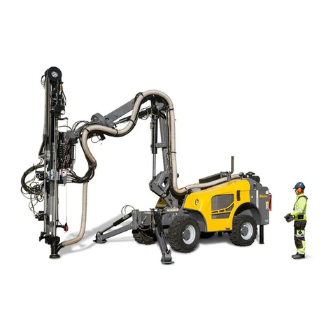
Epiroc SmartROC T35 User manual

SmartROC T35/T40
Safety
Original Instructions
2018-03-09 | No: 5966599819.1.5966707083 en-US


SmartROC T35/T40 Table of Contents
iii No: 5966599819.1.5966707083 en-US
Table of Contents
1 Introduction ........................................................................................................... 5
1.1 The Purpose of the Safety Manual ...........................................................................................5
1.2 Target Group ..............................................................................................................................5
1.3 Safety Messages in Publications..............................................................................................5
1.4 Feedback and Contact Information ..........................................................................................6
2 Product Liability .................................................................................................... 7
3 Risks and Hazards ................................................................................................ 9
3.1 Stored Energy Hazard................................................................................................................9
3.2 Burn Hazard................................................................................................................................9
3.3 Entanglement and Shearing Hazard.......................................................................................10
3.4 Crushing Hazard ......................................................................................................................10
3.5 Tipping Hazard .........................................................................................................................11
3.6 Scalding Hazard .......................................................................................................................11
3.7 Wire Rope Break Hazard .........................................................................................................12
3.8 Pressurized Systems Hazard ..................................................................................................12
3.9 Hazard Zone..............................................................................................................................12
3.10 Work Requiring Special Authorization...................................................................................13
4 Safety Precautions.............................................................................................. 15
4.1 General Safety Guidelines.......................................................................................................15
4.2 Personal Protection .................................................................................................................15
4.3 Safety During Lifting, Installing, and Connecting.................................................................16
4.4 Safety Precautions during Tramming ....................................................................................16
4.5 Safety Precautions during Operation.....................................................................................16
4.6 Safety Precautions during Service and Maintenance...........................................................17
4.7 Safety Guidelines, Working with Pressurized Components ................................................17
4.8 Safety Guidelines, Working with Compressor ......................................................................17
5 Safety Functions ................................................................................................. 19
5.1 Emergency Stop.......................................................................................................................19
5.1.1 Location of Emergency Stop ..................................................................................................19
5.1.2 Resetting Emergency Stop.....................................................................................................21
5.2 Guard.........................................................................................................................................22
5.3 FOPS and ROPS.......................................................................................................................22
5.4 Firefighting Equipment............................................................................................................23
5.4.1 Fire Prevention Readiness .....................................................................................................23
5.4.2 Automatic Fire Suppression System ......................................................................................23
5.4.3 Description of Fire Extinguishers............................................................................................24
5.4.4 Location of Fire Extinguishers ................................................................................................24
5.4.5 In Case of Fire - Fire Extinguisher..........................................................................................25
5.4.6 Actions after Fire ....................................................................................................................25
5.5 Emergency Exit ........................................................................................................................26
6 Warning Signals .................................................................................................. 27
6.1 Warning Beacon.......................................................................................................................27

SmartROC T35/T40 Table of Contents
iv No: 5966599819.1.5966707083 en-US
6.2 Warning Beacon - Automatic Systems ..................................................................................28
6.3 Signal Horn Button Location ..................................................................................................28
7 Noise and Vibration ........................................................................................... 31
7.1 Noise Levels and Vibration Values.........................................................................................31
7.2 Declared Values .......................................................................................................................31
7.3 Causes of High Noise Levels ..................................................................................................32
7.4 Effects of Noise ........................................................................................................................32
7.5 Noise Reduction Factors.........................................................................................................32
7.6 Noise Combined with Other Risk Factors .............................................................................32
7.7 Factors Affecting Whole Body Vibration ...............................................................................33
7.8 Vibration Reduction .................................................................................................................33
8 Signs .................................................................................................................... 35
8.1 General Guidelines .................................................................................................................35
8.2 Warning Signs ..........................................................................................................................35
8.3 Mandatory Action Signs ..........................................................................................................36
8.4 Prohibition Signs .....................................................................................................................37
8.5 Information Signs.....................................................................................................................37
8.6 Fire Equipment Signs ..............................................................................................................38
8.7 Data Plate..................................................................................................................................39
8.8 Type Designation Signs for Ordering Spare Parts ...............................................................39
9 Stability ................................................................................................................ 41
9.1 Spirit Level................................................................................................................................41
10 Environmental Protection .................................................................................. 43
10.1 Environmental Guidelines.......................................................................................................43
10.2 Oils and Greases......................................................................................................................43
10.3 Fuel Spill ...................................................................................................................................43
10.4 Exhaust Gases .........................................................................................................................43
10.5 Handling of Spills and Waste during Maintenance...............................................................43
10.6 End-User Responsibility during Disposal of the Machine ...................................................44
11 EC - Declaration of Conformity.......................................................................... 45

SmartROC T35/T40 1 Introduction
5 No: 5966599819.1.5966707083 en-US
1 Introduction
1.1 The Purpose of the Safety Manual
This Safety manual contains important information that must be followed to prevent acci-
dents and property damage while working with and around the machine. The manual is de-
signed to do the following:
•Provide information on how to detect and prevent hazardous situations
•Provide information about the safe, correct, and economical use of the machine and
related equipment
•Provide information on risks involved and the hazard zones
•Provide information on safety equipment and the safety signs posted on the machine
•Provide information about environmental regulations
This manual is one part of the complete machine delivery and its related equipment.
This manual does not replace the necessary training that is required for the handling of the
machine and its related equipment.
The information in this manual and all applicable local regulations must be followed.
1.2 Target Group
The information in this publication is intended for everyone involved in the application, op-
eration, and maintenance of the machine and related equipment. All readers are expected
to possess basic competence regarding mining methods, construction methods, and the
machines used for that kind of operation.
1.3 Safety Messages in Publications
Safety messages in publications declare hazards and the related measures to avoid the
hazards in that particular situation. The safety messages contain signal words (Danger,
Warning, Caution, and Notice) that relate to the consequences of those specific hazards.
The information in safety messages must always be followed.
The following are examples of how safety messages are structured. Safety messages con-
tain:
•Signal word (determining the degree of the hazard)
•Hazard - stating what the hazard deals with (rotating parts, tipping hazard)
•Consequence of the hazard, if not avoided
•Explanation on how to avoid the hazard
DANGER
Hazard
The signal word "DANGER" indicates a hazardous situation which, if not avoided, will
result in death or serious injury.
uHow to avoid the hazard is written here

SmartROC T35/T40 1 Introduction
6 No: 5966599819.1.5966707083 en-US
WARNING
Hazard
The signal word "WARNING" indicates a hazardous situation which, if not avoided,
could result in death or serious injury.
uHow to avoid the hazard is written here
CAUTION
Hazard
The signal word "CAUTION" indicates a hazardous situation which, if not avoided,
could result in minor or moderate injury.
uHow to avoid the hazard is written here
NOTICE
Hazard
The signal word "NOTICE" contains information considered important, yet not related to
bodily injury. In a "NOTICE" the damage is related to machines, components, or sys-
tems.
uHow to avoid the hazard is written here
1.4 Feedback and Contact Information
Epiroc works actively to develop and continuously improve its products and associated
documentation. Provide your feedback on products and documentation by contacting your
local supplier at https://www.epiroc.com, under "Contact us."

SmartROC T35/T40 2 Product Liability
7 No: 5966599819.1.5966707083 en-US
2 Product Liability
The owner or lessee is responsible for:
•Using the machine only for intended purposes
•Knowing the limitations of the machine and not exceeding the design limits
•Following the instructions in the relevant machine documentation
•Using the machine only when it is in good condition and fully-maintained
•Providing safety training and making sure that all local regulations are followed
•Obtaining and distributing the relevant documentation to operating personnel, mainte-
nance personnel, and other relevant personnel

SmartROC T35/T40 2 Product Liability
8 No: 5966599819.1.5966707083 en-US

SmartROC T35/T40 3 Risks and Hazards
9 No: 5966599819.1.5966707083 en-US
3 Risks and Hazards
3.1 Stored Energy Hazard
Before operating the machine, personnel must be aware of the following information re-
garding the dangers from stored energy.
•Personnel must be aware of how the hydraulic components can move.
•Personnel must be aware of how the hydraulic system controls components.
•Personnel must be aware of how related control circuits affect the hydraulic compo-
nents.
•Personnel must prevent movement of any component that could cause personal injury
and property damage.
•Personnel must make sure that no part of the body is in a position where component
movement can cause physical injury.
•Personnel must be aware of situations where component movement cannot be pre-
vented, such as:
–If the hydraulic system fails
–If the hydraulic system disengages
–If the hydraulic system receives a control signal resulting in component move-
ment
•Personnel must release all sources of potential energy.
•Personnel must make sure that any possible component or machine movement is me-
chanically prevented.
3.2 Burn Hazard
Burn Hazard
The hot surface of the particulate filter and the exhaust pipe can cause a risk of being
burned.
To minimize risk:
•Stay clear of the particulate filter and the exhaust pipe during regeneration.

SmartROC T35/T40 3 Risks and Hazards
10 No: 5966599819.1.5966707083 en-US
3.3 Entanglement and Shearing Hazard
Entanglement and Shearing Hazard
Rotating and moving parts can cause a risk of entanglement or shearing.
To minimize risk:
•Stay clear of the machine work area during operation.
3.4 Crushing Hazard
Crushing Hazard
The movable parts of the boom system can cause a risk of being crushed.
To minimize risk:
•Stay clear of the machine work area during operation.

SmartROC T35/T40 3 Risks and Hazards
11 No: 5966599819.1.5966707083 en-US
3.5 Tipping Hazard
Tipping Hazard
To minimize risk:
•Never exceed the maximum allowed inclination angles for the machine.
•Always wear a seat belt when operating the machine.
3.6 Scalding Hazard
Scalding Hazard
High liquid temperature can causes a risk of scalding.
To minimize risk:
•Release pressure before removing the radiator filler cap (A).
•Release pressure before removing the filler plug (B) on the compressor oil tank.

SmartROC T35/T40 3 Risks and Hazards
12 No: 5966599819.1.5966707083 en-US
3.7 Wire Rope Break Hazard
Wire Rope Break Hazard
Breakage of winch wire rope can cause a risk of tipping, sliding, or whipping.
To minimize risk:
•Always perform the checks described in the operation instructions before using the
winch.
3.8 Pressurized Systems Hazard
Leaking fluid systems can cause fluid injection into flesh and erosion of flesh.
How to minimize the risk:
•Make sure that the system is depressurized before maintenance work is started.
•Replace worn hoses.
•Never replace high-pressure hoses with hoses of lower quality than the original.
•Never replace high-pressure hoses with hoses fitted with removable couplings.
3.9 Hazard Zone
Hazard zones are areas within or around the machine in which a person can be exposed to
a hazard. Take necessary precautions while working within a hazard zone.
Hazard Zone during Tramming

SmartROC T35/T40 3 Risks and Hazards
13 No: 5966599819.1.5966707083 en-US
Hazard Zone during Bench Drilling
Hazard Zone during Toe-Hole Drilling
3.10 Work Requiring Special Authorization
All diagnoses, repairs, maintenance, and troubleshooting must be done only by authorized
or trained personnel, depending on the type of system.
•Electrical system
•Climate control unit
•Air and hydraulic system
•Mechanical system
•Machine software
•Crawler tracks

SmartROC T35/T40 3 Risks and Hazards
14 No: 5966599819.1.5966707083 en-US

SmartROC T35/T40 4 Safety Precautions
15 No: 5966599819.1.5966707083 en-US
4 Safety Precautions
4.1 General Safety Guidelines
•Personnel operating the machine must be trained and knowledgeable about the ma-
chine and the dangers involved.
•Follow the safety instructions and observe the warnings provided in the machine docu-
mentation.
•Have manuals readily available to the operator.
•Observe local safety and health regulations.
•Before starting the machine, make sure that all personnel is cleared from the machine
hazard zones.
•Observe the machine warning signals.
•Check the safety equipment and emergency stops before each shift and after moving
the machine.
•Step on designated areas only. Do not step on open hatches.
•If the machine or a machine system stops due to an indicated fault, do not use the
equipment. Call maintenance personnel.
•Use the equipment only after all faults are rectified.
•Make sure that all control levers are working satisfactorily.
•Perform daily maintenance checks before each shift.
•Work done with the machine involves impact on the surrounding environment, for ex-
ample, vibrations and landslides. All work must be done in accordance with the local
safety directives.
•Make sure that needless tools and material are cleared from the work area.
•Checks and adjustments made while the machine is in operation must include at least
two people. One person must be within the reach of an emergency stop, while having
a good overview of the work.
•No work must be done near the machine when there is a risk of lightning.
4.2 Personal Protection
•Always use the following while working with or near the machine:
–Safety helmet
–Approved and close-fitting clothing with high visibility
–Safety shoes or boots
–Hearing protection
–Protective safety glasses
–Seat belt
–Other necessary safety gear
•Secure long hair.
•Do not wear jewelry.
•Always use protective gloves while handling components, cleaning the machine, and
doing maintenance.
•Use hearing protection with high noise reduction capacity.
For some applications, sound pressure levels can be high even with hearing protection.

SmartROC T35/T40 4 Safety Precautions
16 No: 5966599819.1.5966707083 en-US
•Always use protective safety glasses when using a hammer, as chips or debris can
cause eye injury.
•Use a hammer with a soft face when driving hardened pins.
•Use a respirator in dusty conditions.
•Make sure that compressed air for cleaning the machine does not exceed 2 bar (30
psi).
•Wear a protective face shield and clothing when cleaning with compressed air.
4.3 Safety During Lifting, Installing, and Connecting
Make sure that the following conditions are met while lifting, installing, and connecting the
machine or its equipment:
•Make sure that only authorized personnel lift, install, and connect the equipment.
•Use lifting devices for lifting heavy components.
•Use only approved tools and methods.
•Use lifting devices that are inspected and approved and are in compliance with local
regulations.
•Attach lifting devices only to specified lifting points.
•Make sure that no personnel are present below suspended loads.
•Use only ladders and platforms designed for that specific purpose.
4.4 Safety Precautions during Tramming
•Follow local traffic regulations.
•Observe that no personnel are present within the machine hazard zone or in the direc-
tion of travel.
•Be cautious that impaired visibility can cause a collision risk and also severe injuries.
•Always check ground conditions where the machine is in operation.
•Adapt the speed to the terrain.
•Never exceed the maximum allowed inclination angles for the machine.
•Make sure that the boom system is set to the correct tramming position.
4.5 Safety Precautions during Operation
•Check that pedals and controls are easily accessed by the operator before starting the
machine. If the controls are not accessible to the operator, the machine must not be
operated.
•Make sure that all warning signals on the machine are tested before starting the ma-
chine (for example, brake lights, and turn signal).
•Make sure that all controls, indicators, and fire extinguishers (optional items) are work-
ing satisfactorily.
•Make sure that all warning signs and safety labels are in place, clean, and fully legible.
•Always test the brakes before operating the machine.
•Report any damage or defects immediately.
•Keep all doors closed while the machine is in operation in order to not disrupt the flow
of cooling air and to avoid reducing the amount of noise suppression. A door can be
kept open for a short period, only if necessary.
•Turn the rotation off when manually handling drill bits and drill rod.

SmartROC T35/T40 4 Safety Precautions
17 No: 5966599819.1.5966707083 en-US
•Activate the machine functionality of collecting dust (water flushing, water mist, or dust
collector) during drilling. Rock dust is created during the drilling process and is harmful
to the health.
•Stay clear from the exhaust cleaning unit and the exhaust pipes on exhaust openings.
High temperature gases escape from the unit.
•Switch off the diesel engine before refueling. Do not handle flammable liquids near hot
surfaces, sparks, or a naked flame.
•During regeneration the exhaust gases and the exhaust system become extremely
hot. Do not touch the exhaust system. Do not cover the exhaust system or expose it to
any flammable materials.
•Perform standstill regeneration only on an open terrain and within a safe distance to
flammable objects.
4.6 Safety Precautions during Service and Maintenance
•Turn off the machine.
•Switch off the main power supply.
•Switch off the battery isolation switch and secure it with a security pin.
•Follow maintenance procedures in accordance with the maintenance schedule.
•Before working on the machine, make sure that all parts are cooled down.
•Start service or maintenance on the machine only when the machine is on firm and
level ground.
•Make sure that the work area is illuminated and clean.
•Make sure that systems are depressurized before starting service or maintenance.
•Make sure that the electrical system is de-energized before starting service or mainte-
nance.
•Secure and strap moveable components before starting service or maintenance.
•If one or more of the following conditions are required for fault-finding or other work,
the task must be done by at least two people. One person must be within the reach of
an emergency stop while having a good overview of the work being done.
–The motors or engines are switched on.
–The hydraulic pumps are activated.
–The hydraulic, pneumatic, or water systems are pressurized.
–The electric power is switched on.
4.7 Safety Guidelines, Working with Pressurized
Components
•Pressurized components must not be exposed to welding or heat treatment.
•Safety equipment such as pressure gauges, over-pressure control devices, and safety
valves must be used while working with pressurized components.
•Installation, design, and connections related to the pressure valve must not be modi-
fied.
4.8 Safety Guidelines, Working with Compressor
•Stop the machine if there is an indication that the compressor is overheated.
•Do not open any inspection hatch until the equipment has cooled down.
•Check and maintain the safety devices such as safety valves and over-pressure de-
vices regularly.

SmartROC T35/T40 4 Safety Precautions
18 No: 5966599819.1.5966707083 en-US
•Avoid clogging the compressor with paint, carbonized oil, or dirt, which could disrupt
compressor operation.
•Check pressure and control gauges regularly and replace with new ones when they
can no longer measure the permitted values.
•Position the machine so that no dust blows against it.
•Close the compressor air outlet valve before connecting or disconnecting a hose.
Make sure that the hose is fully-vented before disconnecting.
•Make sure that the open end of the hose or air line is steady before blowing com-
pressed air from the other end. Impact from a loose end could cause injury or damage.
•Do not use external force on the air outlet valves, for example, pulling the hoses.
•Do not install additional equipment directly on an air outlet valve, for example, a water
separator or a lubricating device.
•Use distribution lines, hose couplings, clamps, and air hoses which are of correct di-
mension and suitable for the working pressure. Do not use damaged or worn hoses.
•Make sure that there is no pressure before removing the oil filler plug.

SmartROC T35/T40 5 Safety Functions
19 No: 5966599819.1.5966707083 en-US
5 Safety Functions
5.1 Emergency Stop
NOTICE
Machine Damage
Incorrect use of emergency stops can cause technical problems or damage to the ma-
chine and related equipment.
uOnly use emergency stops in hazardous situations, or when a hazardous situation is
likely to arise.
Example of an Emergency Stop
•In the event of hose rupture or other dangerous situation, activate the emergency
stops to stop the diesel engine and the hydraulic pumps automatically.
5.1.1 Location of Emergency Stop
All machines with cab have at least two emergency stops, one in the cab and one on the
feed.

SmartROC T35/T40 5 Safety Functions
20 No: 5966599819.1.5966707083 en-US
Emergency Stops on Drill Rig
A Trip wire
B Reset button - emergency stop cable
C Trip edge, only on SmartROC T35, T40, T45, C50, and FlexiROC T45
D Reset button
E Emergency stop in cab
F Extra emergency stops, only on SmartROC Series and FlexiROC T45
!NOTE: The remote control unit is optional equipment for the FlexiROC T35, T40, T45,
SmartROC T35, T40, and T45. It is available as a winch control unit or a radio control
unit.
Other manuals for SmartROC T35
1
This manual suits for next models
1
Table of contents
Other Epiroc Construction Equipment manuals
Epiroc
Epiroc DEQ171257 User manual

Epiroc
Epiroc Secoroc COP 44 Specifications

Epiroc
Epiroc EC 90T User manual

Epiroc
Epiroc EC Series Maintenance and service guide
Epiroc
Epiroc Secoroc COP 54 User manual
Epiroc
Epiroc COP M6 Specifications
Epiroc
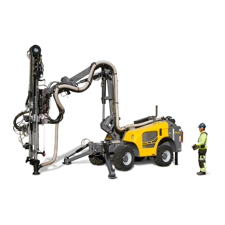
Epiroc Flexi ROC T20 R Instructions for use

Epiroc
Epiroc SB 52 User manual

Epiroc
Epiroc HC Series Maintenance and service guide
Epiroc
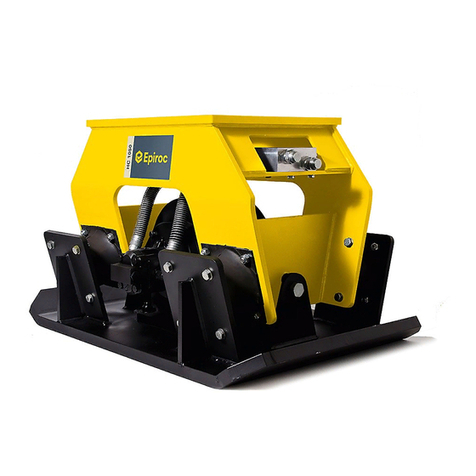
Epiroc HM Series Maintenance and service guide