Epiroc HB 5800 Maintenance and service guide

HB 5800, 5800 DP, 7000, 7000 DP, 10000 DP
Safety and operating instructions
Hydraulic breakers
© Construction Tools GmbH | 3390 5204 01 | 2021-04-19
Original Instructions
Interactive and updated spare part catalogues go to:
www.epiroc.com/docmine
For log in details please contact your local Epiroc office or dealer in your area
Static PDF spare part catalogues go to:
www.podshop.se/epiroc


Contents
© Construction Tools GmbH | 3390 5204 01 | 2021-04-19
Original Instructions
3
Table of Contents
1 Introduction ................................................................................................................................7
1.1 About these Safety and Operating Instructions...............................................................................................7
2 Safety instructions.....................................................................................................................8
2.1 Signal words........................................................................................................................................................8
2.2 Qualification ........................................................................................................................................................9
2.3 Intended use ........................................................................................................................................................9
2.4 Use other than intended .....................................................................................................................................9
2.5 Protective equipment........................................................................................................................................10
2.6 Carrier, precautions ..........................................................................................................................................10
2.7 Transport, precautions .....................................................................................................................................10
2.8 Hydraulic installation, precautions .................................................................................................................11
2.9 Special parts, precautions ...............................................................................................................................11
2.9.1 HP-accumulator...............................................................................................................................................11
2.9.2 Piston accumulator ..........................................................................................................................................11
2.10 Media/consumables, precautions....................................................................................................................12
2.11 Explosion and fire, precautions.......................................................................................................................12
2.12 Electrical shock, precautions ..........................................................................................................................13
2.13 Falling stones, precautions..............................................................................................................................13
2.14 Emissions, precautions....................................................................................................................................13
2.15 Handling machines, precautions.....................................................................................................................13
2.16 Repair, precautions...........................................................................................................................................14
2.17 Changes to the hydraulic attachment, precautions.......................................................................................14
2.18 Environmental pollution, precautions.............................................................................................................14
3 Overview ...................................................................................................................................15
3.1 Equipment description .....................................................................................................................................15
3.2 Function .............................................................................................................................................................15
3.3 Signs / labels .....................................................................................................................................................16
3.3.1 Name plate ......................................................................................................................................................16
3.3.2 Labels ..............................................................................................................................................................16
3.3.3 Signs................................................................................................................................................................16
3.4 Applications.......................................................................................................................................................17
3.5 Guarantee ..........................................................................................................................................................17
3.6 Removing the packaging..................................................................................................................................17
3.7 Scope of delivery ..............................................................................................................................................17
4 Transport ..................................................................................................................................18
4.1 Transport using a crane ...................................................................................................................................19
4.2 Transport using a forklift truck........................................................................................................................19
4.3 Transport using a truck ....................................................................................................................................20
5 Installation ................................................................................................................................21
5.1 Media/consumables ..........................................................................................................................................21
5.1.1 Mineral hydraulic oil.........................................................................................................................................21

Contents
4 © Construction Tools GmbH | 3390 5204 01 | 2021-04-19
Original Instructions
5.1.2 Non-mineral hydraulic oil .................................................................................................................................21
5.1.3 Grease.............................................................................................................................................................21
5.1.4 Gas ..................................................................................................................................................................21
5.2 Manufacturing the adapter plate......................................................................................................................22
5.3 Installing the adapter plate...............................................................................................................................22
5.4 Attaching the hydraulic attachment to the carrier .........................................................................................23
5.4.1 Mechanical mounting aspects .........................................................................................................................23
5.4.2 Making the hydraulic connections ...................................................................................................................23
5.5 Removing the hydraulic attachment from the carrier....................................................................................25
5.5.1 Dismantling the hydraulic connections ............................................................................................................25
5.5.2 Mechanical disassembly..................................................................................................................................25
5.6 Removing the adapter plate .............................................................................................................................26
5.7 DustProtector ....................................................................................................................................................26
5.7.1 Removal ..........................................................................................................................................................26
5.7.2 Installation .......................................................................................................................................................26
5.8 Working tool ......................................................................................................................................................27
5.8.1 Selecting the right working tool........................................................................................................................27
5.8.2 Installation .......................................................................................................................................................28
5.8.3 Removal ..........................................................................................................................................................29
6 Operation ..................................................................................................................................30
6.1 Initial operation and operation after long storage .........................................................................................30
6.2 Preparations before starting ............................................................................................................................31
6.3 Switching the hydraulic breaker on and off ...................................................................................................31
6.4 Functional test...................................................................................................................................................31
6.5 Correct operation ..............................................................................................................................................32
6.5.1 Working angle..................................................................................................................................................32
6.5.2 Advance...........................................................................................................................................................32
6.5.3 Impact time ......................................................................................................................................................32
6.5.4 High ambient temperature ...............................................................................................................................33
6.5.5 Low ambient temperature................................................................................................................................33
6.6 Prohibited operation .........................................................................................................................................33
6.6.1 Lifting/Transporting..........................................................................................................................................33
6.6.2 Impacting .........................................................................................................................................................33
6.6.3 Moving objects.................................................................................................................................................34
6.6.4 Levering...........................................................................................................................................................34
6.6.5 Blank firing of the working tool.........................................................................................................................34
6.6.6 Cylinder end positions .....................................................................................................................................35
6.7 Working with safety equipment .......................................................................................................................35
6.7.1 Underwater applications ..................................................................................................................................35
6.7.2 Usage in tunnels..............................................................................................................................................35
6.7.3 Hot applications ...............................................................................................................................................35
6.8 AutoControl System .........................................................................................................................................36
6.8.1 AutoControl in daily use...................................................................................................................................36
6.8.2 AutoControl in special applications..................................................................................................................36
6.9 Intelligent Protection System (IPS) .................................................................................................................36
6.10 PowerAdapt .......................................................................................................................................................36
7 Maintenance .............................................................................................................................37
7.1 Maintenance schedule......................................................................................................................................38
7.2 Depressurising the hydraulic system .............................................................................................................39
7.3 Cleaning .............................................................................................................................................................40

Contents
© Construction Tools GmbH | 3390 5204 01 | 2021-04-19
Original Instructions
5
7.3.1 Preparations ....................................................................................................................................................40
7.3.2 Procedure ........................................................................................................................................................40
7.4 Lubrication.........................................................................................................................................................40
7.4.1 Checking the lubricant film ..............................................................................................................................40
7.4.2 Automatic lubrication .......................................................................................................................................41
7.4.3 Replacing the lubricant cartridge .....................................................................................................................41
7.4.4 ContiLube®II operation................................................................................................................................... 41
7.4.5 Manual lubrication ...........................................................................................................................................42
7.4.6 Chisel paste filling device ................................................................................................................................42
7.5 Checking the tensioning bolts.........................................................................................................................43
7.6 Checking the working tool ...............................................................................................................................43
7.7 Checking the retainer bars...............................................................................................................................44
7.8 Checking the percussion piston impact surface ...........................................................................................44
7.9 Checking the wear bushes and impact ring ...................................................................................................45
7.10 Checking and cleaning the DustProtector system ........................................................................................46
7.11 Piston accumulator...........................................................................................................................................47
7.11.1 Checking the pressure in the piston accumulator............................................................................................48
7.11.2 Release the pressure from the piston accumulator .........................................................................................48
7.11.3 Filling / topping up the piston accumulator ......................................................................................................48
7.12 HP-accumulator.................................................................................................................................................49
7.12.1 Visual check ....................................................................................................................................................50
7.12.2 Checking the fastening screws........................................................................................................................50
7.12.3 Checking the gas pressure..............................................................................................................................50
7.13 Checking the hydraulic lines ...........................................................................................................................51
7.14 Checking and cleaning the hydraulic oil filter................................................................................................51
7.15 Checking the adapter plate and the breaker box for cracks and/or wear....................................................52
7.16 Checking the adapter plate bolts for wear......................................................................................................52
7.17 Bolt connections / Tightening torques ...........................................................................................................53
8 Troubleshooting.......................................................................................................................55
8.1 The hydraulic breaker does not start ..............................................................................................................55
8.2 Hydraulic breaker operates too slowly ...........................................................................................................55
8.3 Impact force too low .........................................................................................................................................56
8.4 Impact rate too high and impact force too low ..............................................................................................56
8.5 Oil leaks from ports »P« und »T« ....................................................................................................................56
8.6 Oil escapes between the cylinder cover and the cylinder ............................................................................57
8.7 Oil escapes from parts of the hydraulic breaker installation (connecting fittings, hoses etc.) ................57
8.8 Oil escapes from the working tool ..................................................................................................................57
8.9 Oil escapes from the high pressure accumulator..........................................................................................57
8.10 Oil or grease escapes from the ContiLube®II ...............................................................................................57
8.11 Operating temperature too high ......................................................................................................................58
8.12 Pressure line »P« flails violently .....................................................................................................................58
9 Repair ........................................................................................................................................59
9.1 Sending in the hydraulic attachment for repairs ...........................................................................................59
10 Storage......................................................................................................................................60
10.1 Hydraulic breaker..............................................................................................................................................60
10.1.1 Short storage ...................................................................................................................................................60

Contents
6 © Construction Tools GmbH | 3390 5204 01 | 2021-04-19
Original Instructions
10.1.2 Long storage....................................................................................................................................................60
10.1.3 How to proceed after more than twelve months‘ storage ................................................................................60
10.2 Working tool ......................................................................................................................................................61
10.3 Grease cartridges..............................................................................................................................................61
11 Disposal ....................................................................................................................................62
11.1 Hydraulic breaker..............................................................................................................................................62
11.2 Hydraulic hoses ................................................................................................................................................62
11.3 Hydraulic oil.......................................................................................................................................................62
11.4 Chisel paste and grease cartridges.................................................................................................................62
12 Technical specifications..........................................................................................................63
12.1 Noise declaration statement ............................................................................................................................64
13 EC Declaration of Conformity (EC Directive 2006/42/EC) ....................................................65

Safety and operating instructions
© Construction Tools GmbH | 3390 5204 01 | 2021-04-19
Original Instructions
7
1 Introduction
Epiroc is a leading productivity partner for the mining, in-
frastructure and natural resources industries. With cut-
ting-edge technology, Epiroc develops and produces in-
novative drill rigs, rock excavation and construction
equipment, and provides world-class service and con-
sumables.
The company was founded in Stockholm, Sweden, and
has passionate people supporting and collaborating with
customers in more than 150 countries.
Construction Tools GmbH
P.O. Box: 102152
Helenenstraße 149
D - 45021 Essen
Tel.: +49 201 633-0
1.1 About these Safety and
Operating Instructions
The aim of these Instructions is to familiarise you with
the safe and effective operation of the hydraulic attach-
ment. You will also find instructions for regular mainte-
nance activities for the hydraulic attachment in this docu-
ment.
Please read these Instructions carefully prior to the first
attachment and use of the hydraulic attachment.
In these instructions, the DustProtector version of the hy-
draulic breaker will be referred to by the abbreviation
DP.
The different designation of the texts means as follows:
►
Action step in a safety instruction
♦
Action step
1.
2.
Established operation process
A
B
C
Explanation of the elements of a drawing
•
•
•
Listing
Symbols used in illustrations have the following mean-
ings:
permitted operation
prohibited operation

Safety and operating instructions
8 © Construction Tools GmbH | 3390 5204 01 | 2021-04-19
Original Instructions
2 Safety instructions
This is the safety alert symbol. It is used to alert
you to potential personal injury hazards. Obey
all safety messages that follow this symbol to
avoid possible injury or death.
Read these Safety and operating instructions
and specifically all safety instructions before us-
ing the hydraulic attachment. This will:
• prevent the risk of injuries and fatal accidents for
yourself and others,
• protect the environment against environmental dam-
age.
• protect the hydraulic attachment and other property
against material damage,
Follow all instructions in these Safety and operating in-
structions.
Store these Safety and operating instructions in the doc-
ument compartment of the carrier cab.
Anyone
• transporting,
• installing or removing,
• operating,
• maintaining,
• repairing,
• storing or
• disposing of
the hydraulic attachment must have read and under-
stood these Safety and operating instructions.
These Safety and operating instructions belong to the
hydraulic attachment. Keep it for the life of the product.
Ensure, if applicable, that any received amendment is in-
corporated in the instructions. Hand over the Safety and
operating instructions if ever you lend, rent out or sell the
hydraulic attachment.
All safety regulations listed in this manual comply with
the laws and regulations of the European Union. Also
observe the additional national/regional regulations.
Hydraulic attachment operation outside the European
Union is subject to the laws and regulations valid in the
country of use. Please observe any other, more stringent
regional regulations and legislation.
Read the carrier manufacturer's Safety and operating In-
structions before attaching the hydraulic attachment to
the carrier and operating it. Observe all instructions.
2.1 Signal words
The signal words Danger, Warning, Caution, and Notice
are used as follows in these Safety and operating in-
structions:
DANGER indicates a hazardous situation
which, if not avoided, will result in
death or serious injury.
WARNING indicates a hazardous situation
which, if not avoided, could result in
death or serious injury.
CAUTION indicates a hazardous situation
which, if not avoided, could result in
minor or moderate injury.
NOTICE The signal word NOTICE is used to
address practices related to possible
property damage but not related to
personal injury.

Safety and operating instructions
© Construction Tools GmbH | 3390 5204 01 | 2021-04-19
Original Instructions
9
2.2 Qualification
Transporting the hydraulic attachment is only permitted
if carried out by people who:
• are authorised to operate a crane or a forklift truck
according to the applicable national provisions,
• know all the relevant national/regional safety provi-
sions and accident prevention rules,
• have read and understood the safety and transport
chapter of these Safety and operating instructions.
Installing, maintaining, storing and disposing of the
hydraulic attachment are only permitted if carried out by
people who:
• know all the relevant national/regional safety provi-
sions and accident prevention rules,
• have read and understood these Safety and operat-
ing instructions.
Operating the hydraulic attachment is only permitted if
carried out by qualified carrier drivers. Carrier drivers are
qualified if they:
• have been trained to operate a carrier according to
the national regulations,
• know all the relevant national/regional safety provi-
sions and accident prevention rules,
• have read and understood these Safety and operat-
ing instructions.
Testing the hydraulic installation is only permitted if
carried out by professionals. Professionals are people
who are authorised to approve a hydraulic installation for
operation according to the national regulations.
Repairing the hydraulic attachment is only permitted if
carried out by professionals trained by Construction
Tools GmbH. These professionals must have read and
understood these Safety and operating instructions.
They must follow all safety instructions and guidelines
for repair. Otherwise the operational safety of the hy-
draulic attachment is not guaranteed.
2.3 Intended use
Only attach the hydraulic breaker to a hydraulic carrier of
a suitable load-bearing capacity.
Only use the hydraulic breaker function of the device to
break or fragment concrete, stone and rocks.
Using the hydraulic breaker in and under water, in tun-
nels, under the ground and for hot applications is only
possible if it has been fitted out with special safety equip-
ment.
Intended use also implies observing all instructions in
these Safety and operating instructions.
2.4 Use other than intended
Never operate the hydraulic breaker in an environment
where there is a risk of explosions. Explosions will result
in serious injury or death.
Never use the hydraulic breaker
• to transport or lift objects. The lifted object can fall
and cause serious injuries or death.
• as a sledge hammer. This will damage the hydraulic
breaker, the working tool and the carrier.
• as a crowbar. This can cause the working tool to
break.
• to push debris. This damages the hydraulic breaker.

Safety and operating instructions
10 © Construction Tools GmbH | 3390 5204 01 | 2021-04-19
Original Instructions
2.5 Protective equipment
Personal protective equipment must comply with the ap-
plicable health and safety regulations.
nDo not work wearing jewelry or with loose long hair.
Moving machine parts could catch your hair or jew-
elry causing serious injury.
nWear comfortable, close-fitting work clothes. The
moving machine parts can snag loose clothing and
cause serious injury.
Always wear the following personal protective equip-
ment:
• protective helmet
• safety glasses with side protectors
• protective gloves
• protective shoes
• warning vest
• hearing protection
2.6 Carrier, precautions
WARNING Falling carrier
If the load-bearing capacity of the carrier used is insuffi-
cient, the carrier will not be stable. It can topple over and
cause injuries and damage.
Using a carrier whose load-bearing capacity is too high
will greatly burden the hydraulic attachment causing it to
wear faster.
uOnly attach the hydraulic attachment to a hydraulic
carrier of a suitable load-bearing capacity.
uThe carrier must remain stable at all times.
uRead the carrier manufacturer's Safety and operating
Instructions before attaching the hydraulic attach-
ment to the carrier and operating it. Observe all in-
structions.
NOTICE Damage to the hydraulic attachment
Working with a hydraulic attachment mounted to a long
reach boom may cause damage to the hydraulic attach-
ment.
uBefore working with a hydraulic attachment mounted
to a long reach boom consult the Epiroc Customer
Center / Dealer in your area.
2.7 Transport, precautions
WARNING Risk of death due to suspended loads
When lifting loads these can swing out and fall. This can
result in serious injuries or even death.
uNever stand underneath or in the swinging range of
suspended loads.
uOnly move loads under supervision.
uOnly use approved lifting equipment and lifting gear
with sufficient load bearing capacity.
uDo not use worn lifting gear (ropes, belts, chains,
shackles etc.).
uDo not place lifting gear such as ropes and belts on
sharp edges or corners, do not knot these or twist
them.
uWhen leaving the workplace, set down the load.
WARNING Injury due to swivelling load
When transporting the load by crane it can swivel and
cause severe injuries and considerable damage to prop-
erty.
uEnsure that no personnel, objects or obstacles are
located in the swivel range of the load.
NOTICE Air freight restrictions
HATCON contains an activated SIM card (radio transmit-
ting device) and an encased lithium ion battery after acti-
vation step has been finalized. Both parts are regulated
for air transport.
uConsult your forwarder or local customer center/
dealer about any restrictions for air freight.

Safety and operating instructions
© Construction Tools GmbH | 3390 5204 01 | 2021-04-19
Original Instructions
11
2.8 Hydraulic installation,
precautions
WARNING Hydraulic pressure too high
If the hydraulic pressure is too high, the parts of the hy-
draulic attachment will be exposed to excessively high
loads. Parts can break loose or burst causing serious in-
juries.
uLay the drain line of the pressure relief valve directly
in the tank to ensure the safe functioning of the pres-
sure relief valve!
uThe pressure relief valve must be set at the maxi-
mum static pressure.
uThe pressure relief valve setting must be checked to
ensure that the maximum static pressure (see chap-
ter Technical specifications) of the hydraulic instal-
lation is not exceeded at any time. Attach a lead seal
to the pressure relief valve.
uPrior to their first use, the safety facilities on the hy-
draulic installation must be checked by a profes-
sional/authorised monitoring body for their quality
(CE mark etc.), suitability and proper functioning.
uIf any significant changes are made to the hydraulic
installation, a new acceptance inspection is to be
carried out in accordance with the relevant national
safety provisions.
WARNING Hot hydraulic oil squirting out
The hydraulic system is under high pressure. Hydraulic
lines may spring a leak or burst. Hydraulic oil squirting
out can lead to serious injury.
uWhen attaching the hydraulic attachment do not lay
any hydraulic lines through the carrier's cab.
uOnly use hydraulic lines which comply with the fol-
lowing quality requirements:
- Hydraulic hoses with 4 reinforcement steel wires
according to DINEN856 4SH,
- Hydraulic pipes, seamless cold-drawn steel pipes
according to DINEN10305
2.9 Special parts, precautions
2.9.1 HP-accumulator
DANGER Danger of explosions
The HP-accumulator of the hydraulic breaker is filled
with nitrogen (N2). Filling it with any other gas may trig-
ger an explosion and lead to serious, possibly fatal, in-
juries.
uOnly fill the HP-accumulator with nitrogen (N2).
uDo not carry out any welding and soldering work to
the HP-accumulator.
uCheck the HP-accumulator in accordance with the
national safety provisions.
WARNING Component coming loose abruptly
Risk of bursting
The HP-accumulator is under pressure, even when the
hydraulic system has been depressurised. Screw con-
nections might come loose unexpectedly and cause in-
juries.
uNever unscrew the cover or the upper shell from a
pressurised HP-accumulator.
uNever carry out mechanical processing to the HP-ac-
cumulator.
2.9.2 Piston accumulator
DANGER Danger of explosions
The integrated piston accumulator is filled with nitrogen
(N2). Filling it with any other gas may trigger an explo-
sion and lead to serious, possibly fatal, injuries.
uOnly fill the piston accumulator with nitrogen(N2).
WARNING Component coming loose abruptly
The piston accumulator is under pressure, even when
the hydraulic system has been depressurised. The filling
valve might come loose unexpectedly and cause in-
juries.
uNever unscrew the filling valve »G« from the pres-
surised piston accumulator.

Safety and operating instructions
12 © Construction Tools GmbH | 3390 5204 01 | 2021-04-19
Original Instructions
2.10 Media/consumables,
precautions
WARNING Hot hydraulic oil under high pressure
Hydraulic oil will squirt out under high pressure if there is
a leakage. The jet of oil might penetrate people's skin
and cause permanent damage. Hot hydraulic oil can
cause burns.
uNever use your hands to find leaks.
uAlways keep your face away from a possible leak.
uIf hydraulic oil has penetrated your skin consult a
doctor immediately.
WARNING Hydraulic oil spills
Spilt hydraulic oil can make a floor slippery. If people slip
they can be injured. Hydraulic oil is environmentally
harmful and must not penetrate the ground or enter the
water table or water supplies.
uMake sure not to spill any hydraulic oil.
uImmediately clean the floor if you have spilt hydraulic
oil.
uObserve all safety and environmental protection pro-
visions when handling hydraulic oil.
WARNING Skin infections/diseases due to oil and
grease
Hydraulic oil and grease can cause rashes (or even
eczema) if they come into contact with the skin.
uAvoid all skin contact with hydraulic oil and grease.
uUse a suitable skin protection product.
uAlways wear safety gloves when working with hy-
draulic oil or grease.
uImmediately clean any skin that has been contami-
nated by oil or grease with water and soap.
2.11 Explosion and fire,
precautions
DANGER Explosion and fire
Explosions cause serious injury or death. If the working
tool hits explosives, an explosion may be the result.
uNever operate the hydraulic breaker in the direct
vicinity of explosives.
uMake sure that no explosives are hidden in the rocks
and stones.
uCheck gas line position plans of the entire construc-
tion area.
DANGER Explosion and fire
Operating the hydraulic breaker may create sparks
which ignite highly flammable gases. This may lead to
fire or an explosion.
uNever work in an environment with highly flammable
substances.
uMake sure that there are no hidden sources of gas in
the work area.
uCheck gas line position plans of the entire construc-
tion area.
DANGER Explosion and fire
Dust-rich air can form an explosive atmosphere which
may ignite when operating the hydraulic breaker. This
may lead to fire or an explosion.
uNever use the hydraulic breaker in an explosive at-
mosphere.
uAlways provide sufficient ventilation when working in
buildings or in a confined area.

Safety and operating instructions
© Construction Tools GmbH | 3390 5204 01 | 2021-04-19
Original Instructions
13
2.12 Electrical shock, precautions
DANGER Electrical shock
Any contact of the hydraulic attachment with electric cir-
cuits or other sources of electricity will lead to an electric
shock, resulting in serious injury or death. The hydraulic
attachment is not electrically insulated.
uNever work in the vicinity of electric circuits or other
sources of electricity.
uMake sure that there are no hidden circuits in the
work area.
uCheck wiring diagrams.
2.13 Falling stones, precautions
WARNING Fragments flying around
Fragments of material which come loose while operating
the hydraulic attachment may be flung away and can
cause serious injury if people are hit by them. Small ob-
jects falling from a great height can also cause serious
damage.
During hydraulic attachment operation the danger zone
is considerably greater than during the excavation oper-
ation due to fragments of stone and pieces of steel flying
around, and for this reason the danger zone must, de-
pending on the type of material to be worked on, be en-
larged correspondingly, or secured in a suitable manner
through corresponding measures.
uSecure the danger zone.
uStop the hydraulic attachment immediately if anyone
enters the danger zone.
uClose the windscreen and the side windows of the
driver's cab.
2.14 Emissions, precautions
WARNING Noise hazard
Operating the hydraulic attachment creates a loud noise.
Long term high sound pressure level can affect your
hearing.
uWear suitable hearing protection.
WARNING Lung disease
Dust may be generated when operating the hydraulic at-
tachment. If dust from rocks or silica dust, produced
when operating the hydraulic attachment on rocks, con-
crete, asphalt or other such materials, is inhaled this
may lead to silicosis (dust lungs, a severe lung disease).
Silicosis is a chronic disease which may lead cancer and
death.
uWear a suitable breathing mask.
2.15 Handling machines,
precautions
WARNING Narcotics, alcohol and drugs
Narcotics, alcohol and medicinal drugs make their users
less alert and affect their ability to concentrate. Negli-
gence and incorrectly assessing a situation can result in
serious injury or death.
uNever work on or with the hydraulic attachment when
under the influence of narcotics, alcohol or drugs
which affect your alertness.
uNever allow other people who are under the influ-
ence of narcotics, alcohol or drugs which affect their
alertness to work on or with the hydraulic attach-
ment.

Safety and operating instructions
14 © Construction Tools GmbH | 3390 5204 01 | 2021-04-19
Original Instructions
2.16 Repair, precautions
WARNING Heavy parts falling
The main parts of the hydraulic breaker are heavy. Un-
suitable lifting attachments (e.g. ring or eye bolts) may
fail and cause heavy parts to fall. Falling parts may
cause serious injury.
uNever pull the percussion unit out of the breaker box.
Dismounting the percussion unit is only permitted if
carried out by professionals trained by Construction
Tools GmbH. These professionals must follow all
safety instructions and guidelines for repair.
uThese professionals are only permitted to repair the
percussion unit if they use the sling gears prescribed
by Construction Tools GmbH when:
- removing the complete percussion unit.
- mounting or dismounting parts of the percussion
unit.
2.17 Changes to the hydraulic
attachment, precautions
WARNING Changes to the hydraulic attachment
Changes to the hydraulic attachment or the adapter
plate may lead to serious injury.
uNever carry out any changes to the hydraulic attach-
ment or the adapter plate.
uOnly use original parts or accessories approved by
Epiroc.
uModifications that entail new hazards may require a
new procedure for assessing conformity.
WARNING Changes to the HP-accumulator
Changes to the HP-accumulator may lead to serious in-
jury.
uNever carry out any changes to the HP-accumulator.
uAny modification will result in immediate invalidation
of the operating licence.
2.18 Environmental pollution,
precautions
NOTICE Environmental pollution due to hydraulic oil
Hydraulic oil is permanently environmentally harmful. Es-
caped hydraulic oil will lead to groundwater and soil con-
tamination. Organisms may die.
uCollect any hydraulic oil which escapes to avoid envi-
ronmental pollution. For minor volumes use an ab-
sorbing medium (in case of an emergency use soil).
In case of major leakages contain the hydraulic oil. It
must not drain off and penetrate the ground or enter
the water table or water supplies.
uCollect contaminated absorbing medium or soil in a
watertight box/container and close it tight.
uContact an authorized waste management company.
uDispose of all contaminated material in accordance
with the applicable environmental regulations.

Safety and operating instructions
© Construction Tools GmbH | 3390 5204 01 | 2021-04-19
Original Instructions
15
3 Overview
3.1 Equipment description
The illustration gives an overview of the main parts and
components of the hydraulic attachment. Actual details
may differ.
A
B
CD
E
F
G
H
I
J
K
L
M
M
N
A. The hydraulic breaker is connected to the carrier by
the adapter plate. The adapter plate is not included
in the scope of supply of the hydraulic breaker.
B. Tank line »T«
C. The HP-accumulator compensates pressure varia-
tions in the hydraulic system.
D. Non-return valve of percussion compartment venti-
lation
E. Automatic lubrication system ContiLube®II
F. The percussion piston is guided in the cylinder.
G. The breaker box protects the percussion unit.
H. Working tool aperture protective cap
I. The working tool can be replaced as required. The
working tool is not included in the scope of supply of
the hydraulic breaker.
J. The DustProtector system prevents dust from en-
tering the percussion compartment (only on the
DPversion).
K. The working tool is retained in the lower breaker
part.
L. Pressure line »P«
M. The swivel joint covers protect the swivel joints.
N. The cylinder cover houses the nitrogen gas (N2)
filled piston accumulator and the control mechanism.
3.2 Function
The operation of a hydraulic breaker is described in a
greatly simplified version below:
The pressure line »P« supplies oil at the operating pres-
sure of the carrier to the hydraulic breaker. The tank line
»T« returns the oil to the tank of the carrier. The HP-ac-
cumulator compensates pressure variations in the hy-
draulic system.
The percussion piston moves up and down in the cylin-
der. When the percussion piston is in its lower position, it
impacts the working tool. The percussion energy is
transferred to the material to be broken via the working
tool.

Safety and operating instructions
16 © Construction Tools GmbH | 3390 5204 01 | 2021-04-19
Original Instructions
3.3 Signs / labels
WARNING Missing warnings
The name plate and the labels on the hydraulic attach-
ment contain important information about the hydraulic
attachment and for personal safety. A missing warning
can lead to overlooking or misinterpretation of possible
risks and cause personal hazards. The signs and labels
must always be clearly legible.
uImmediately replace any defective name plates and
labels.
uUse the spare parts list to order new name plates
and labels.
3.3.1 Name plate
A. Model
B. Year of construction of hydraulic attachment
C. Max. permissible operating pressure
D. Weight of hydraulic attachment
E. Serial number
F. Name and address of manufacturer
G. The warning symbol and the book symbol indicate
that the Safety and Operating Instructions must be
read prior to use of the hydraulic attachment and in
particular the chapter on Safety.
H. The CE symbol indicates that the hydraulic attach-
ment was produced in conformity with CE. You can
find further information about this in the enclosed EC
Declaration of Conformity.
I. The EAC symbol means that the machine is EAC
approved.
3.3.2 Labels
Sound Power
WA
xxx
dB
The label states the guaranteed
sound power level in accordance
with EC directive 2000/14/EC.
Transport warning
Never lift the hydraulic breaker
by the transport safety device.
This was not designed for lifting
and might break, causing the hy-
draulic breaker to fall
Lubrication symbol
The label identifies a lubrication
point.
Gas pressure
Gasdruck nur bei betriebswarmem Hammer prüfen!
Only check the gas pressure
when the hammer is at operating temperature!
Ne contrôler la pression d´azote que si le marteau
est à température de service!
Controllare la pressione del gas solo a mortello
a temperature d´esercizio!
¡Controlar la presión del gas sólo con el martillo
a temperatura de régimen!
The label indicates that the gas
pressure can only be checked if
the breaker has reached operat-
ing temperature.
3.3.3 Signs
The warning symbol and the
book symbol indicate that the
Safety and Operating Instruc-
tions must be read prior to use of
the hydraulic attachment and in
particular the chapter on Safety.

Safety and operating instructions
© Construction Tools GmbH | 3390 5204 01 | 2021-04-19
Original Instructions
17
3.4 Applications
Field Type of application
General construction work Trenchwork for utilities,
foundation work
Demolition Heavily reinforced con-
crete, demolition of power
stations and bridges
Rock mining / breaking Primary breaking
Secondary breaking,
bench leveling foundation
work
Tunneling*, mining* Bench levelling
Tunnel driving
High temperature applica-
tions*
Breaking up slag
Underwater applications* Demolition, Deepening
shipping channels
* only after consulting the Epiroc Customer Center /
Dealer in your area
3.5 Guarantee
The guarantee or product liability will be invalidated by
the following:
• Use other than intended
• Maintenance work not being carried out or being
carried out incorrectly
• The use of incorrect consumables
• The use of non-approved parts
• Damage due to wear
• Damage due to improper storage
• Changes not carried out by or in consultation with
the manufacturer
3.6 Removing the packaging
nRemove all the packaging material.
nDispose of it in accordance with the applicable provi-
sions.
nCheck that the delivery is complete.
nCheck the delivery for visual damage.
nIf any defects are found, consult the Epiroc Customer
Center / dealer in your area.
3.7 Scope of delivery
The hydraulic breaker is delivered complete with:
• Hydraulic breaker
• Test gauge lower wear bush
• Safety and Operating instructions
• EC Declaration of Conformity
Accessories as ordered:
• Working tool
• Hoses
• Service box
Special accessories as ordered:
• e.g. adapter plate with Allen screws and pairs of lock
washers
• e.g. base plate to construct an adapter plate with
Allen screws and pairs of lock washers
• e.g. hydraulic fittings for the carrier
• e.g. calliper upper wear bush

Safety and operating instructions
18 © Construction Tools GmbH | 3390 5204 01 | 2021-04-19
Original Instructions
4 Transport
WARNING Hoist tipping over / hydraulic attach-
ment falling
The hydraulic attachment is heavy. The hoist/lifting
equipment and/or hydraulic attachment tipping over or
falling may cause serious injury and material damage.
uOnly transport the hydraulic attachment with lifting
equipment with the right load-bearing capacity for the
weight of the hydraulic attachment.
uOnly lift and secure the hydraulic attachment with lift-
ing gear (ropes, chains, shackles etc.) with the right
load-bearing capacity for the weight to be lifted.
uMake sure that there is nobody near or under the
suspended hydraulic attachment.
WARNING Percussion unit falling
The percussion unit slides out of the breaker box if not
secured by the adapter plate or the transport safety de-
vice. The falling percussion unit may cause serious in-
jury and material damage.
uNever transport a hydraulic breaker without mounted
adapter plate or transport safety device.
uImmediately mount the transport safety device after
removal of the adapter plate.
uThe percussion unit must not move in the breaker
box even if the transport safety device is mounted. A
sliding percussion unit can destroy the transport
safety device.
uReplace a missing elastic pad, if necessary e.g. with
a wooden block. This keeps the percussion unit fixed
in the breaker box during transport.
uImmediately replace a defective transport safety de-
vice. Use the spare parts list to order a new transport
safety device. If not in use save the transport safety
device for future use.
WARNING Hydraulic breaker falling
The lifting eye may fail and cause the hydraulic breaker
to fall. This may cause serious injury and material dam-
age.
uCheck the lifting eye before you lift the hydraulic
breaker. Never lift the hydraulic breaker with the lift-
ing eye if:
● the checkpoints(A) are worn and not protruding
anymore
or
● the checkpoints(B) are worn and not recessed
anymore.
A
B
● the material is worn up to the checkpoints (A, B).
Use permitted
Use prohibited
● the lifting eye is bent.
● you detect cracks in the lifting eye or the weld
seam.
uContact the Epiroc Customer Center / Dealer in your
area if the lifting eye is worn in any way.
Safety and operating instructions
© Construction Tools GmbH | 3390 5204 01 | 2021-04-19
Original Instructions
19
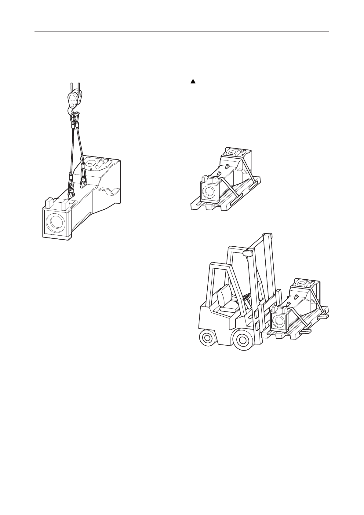
4.1 Transport using a crane
nSecure the hydraulic attachment with ropes or chains
as shown in the following illustration.
nSlowly lift the hydraulic attachment.
nPlace the hydraulic attachment on timber support
blocks.
4.2 Transport using a forklift
truck
WARNING Hydraulic attachment tipping over
The hydraulic attachment tipping off the fork of the forklift
truck or the pallet may cause serious injury.
uPlace the hydraulic attachment on a pallet.
uStrap the hydraulic attachment to the pallet using
suitable strapping, as shown in the illustration below.
uMove the fork of the forklift truck under the pallet so
that the centre of gravity is between the prongs.
nMove the fork of the forklift truck under the pallet so
that the hydraulic attachment cannot tip over.
nSlowly lift the pallet with the hydraulic attachment.
nTransport the pallet with the hydraulic attachment to
the location provided for.

Safety and operating instructions
20 © Construction Tools GmbH | 3390 5204 01 | 2021-04-19
Original Instructions
4.3 Transport using a truck
WARNING Hydraulic attachment tipping over /
slipping
The hydraulic attachment slipping or tipping over and
falling from the loading area of a lorry may cause serious
injury.
uPlace the hydraulic attachment on a pallet.
uStrap the hydraulic attachment to the pallet using
suitable strapping (see illustration in chapter Trans-
port using a forklift truck).
uPlace the pallet with the hydraulic attachment on an
anti-slip mat.
uSecure the hydraulic attachment to the loading area
with ropes or chains; use any available transport
lugs.
nSecure the hydraulic attachment on the pallet and the
loading surface as shown in the following illustration.
nObserve all the applicable national/regional regula-
tions on securing loads.
This manual suits for next models
4
Table of contents
Other Epiroc Industrial Equipment manuals

Epiroc
Epiroc HB Series Maintenance and service guide

Epiroc
Epiroc MB 750 Maintenance and service guide

Epiroc
Epiroc CB Series Maintenance and service guide

Epiroc
Epiroc 140T Maintenance and service guide

Epiroc
Epiroc FORDIA Casing Advancer Standard User manual

Epiroc
Epiroc COP RR14 Guide

Epiroc
Epiroc 90T Maintenance and service guide

Epiroc
Epiroc LPHB-M Maintenance and service guide

Epiroc
Epiroc 70 Maintenance and service guide

Epiroc
Epiroc SmartROC T35 Guide


