Safety and operating instructions
8 © Construction Tools GmbH | 3390 5215 01 | 2019-12-04
Original Instructions
2.2 Qualification
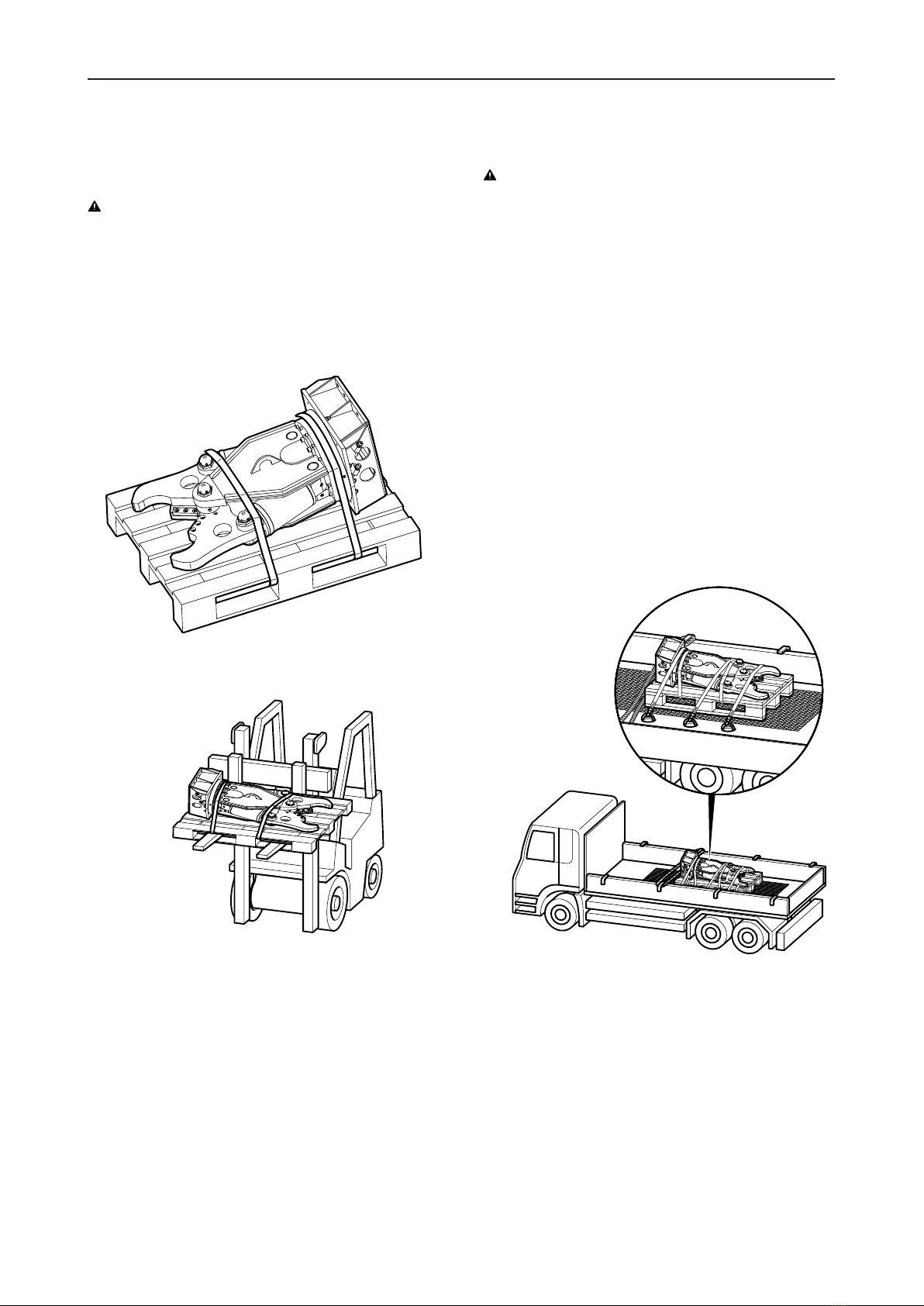
Transporting the hydraulic attachment is only permitted
if carried out by people who:
• are authorised to operate a crane or a forklift truck
according to the applicable national provisions,
• know all the relevant national/regional safety provi-
sions and accident prevention rules,
• have read and understood the safety and transport
chapter of these Safety and operating instructions.
Installing, maintaining, storing and disposing of the
hydraulic attachment are only permitted if carried out by
people who:
• know all the relevant national/regional safety provi-
sions and accident prevention rules,
• have read and understood these Safety and operat-
ing instructions.
Welding of the hydraulic attachment is only permitted if
carried out by qualified welders who:
• have been trained to operate MIG welding equip-
ment according to the national regulations,
• know all the relevant national/regional safety provi-
sions and accident prevention rules,
• have read and understood these Safety and operat-
ing instructions.
Operating the hydraulic attachment is only permitted if
carried out by qualified carrier drivers. Carrier drivers are
qualified if they:
• have been trained to operate a carrier according to
the national regulations,
• know all the relevant national/regional safety provi-
sions and accident prevention rules,
• have read and understood these Safety and operat-
ing instructions.
Testing the hydraulic installation is only permitted if
carried out by professionals. Professionals are people
who are authorised to approve a hydraulic installation for
operation according to the national regulations.
Repairing the hydraulic attachment is only permitted if
carried out by professionals trained by Construction
Tools GmbH. These professionals must have read and
understood these Safety and operating instructions. Oth-
erwise the operational safety of the hydraulic attachment
is not guaranteed.
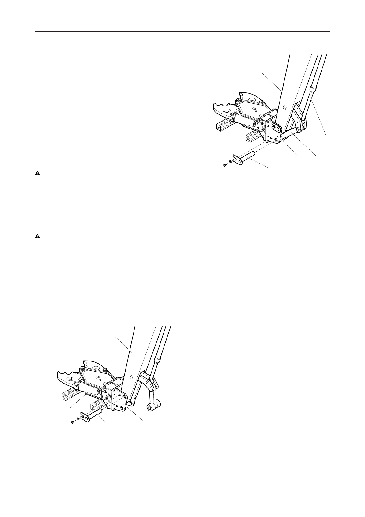
2.3 Intended use
Only attach the hydraulic concrete buster to a hydraulic
carrier of a suitable load-bearing capacity. Read the car-
rier manufacturer's Safety and Operating Instructions be-
fore attaching the hydraulic concrete buster to the carrier
and operating it. Observe all instructions.
Only use the hydraulic jaw function of the equipment for
the following work:
• light demolition work, e.g. narrow, lightly reinforced
concrete elements, masonry
• stripping out and reconstructing interiors
Intended use also implies observing all instructions in
these Safety and Operating Instructions.
2.4 Use other than intended
Never use the hydraulic concrete buster:
• to cut steel plate and sheet metal. This damages the
hydraulic concrete buster.
• as tank shear. This damages the hydraulic concrete
buster.
• to cut high-quality steel grades, tensile strength
>370N/mm², such as railway rails, tram rails and
spring steel. This may damage the hydraulic con-
crete buster. Rails which break during the cutting
process may be flung away and can cause serious
injury if people are hit by them.
• to cut reinforcements with a tensile strength
>500N/mm². This may damage the hydraulic con-
crete buster.
• to cut wire rope. This may damage the hydraulic
concrete buster. Wire ropes that are under tension
can spring away during the cutting process. This can
lead to serious injury if the ropes strike a person.
• to pull/tear at girders, braces and walls. This dam-
ages the hydraulic concrete buster and adapter
plate. The carrier may lose stability. It can topple
over and cause injuries.
• to hit or chop. This destroys the hydraulic concrete
buster.
• as a crow bar. This destroys the hydraulic concrete
buster.
• to push debris. This destroys the hydraulic concrete
buster.
• to move the carrier supported by the hydraulic con-
crete buster. This severely damages the hydraulic
concrete buster.
• to lift or transport loads. This damages the hydraulic
concrete buster.