Equipois zeroG Arm User manual
Arm Operator’s Reference
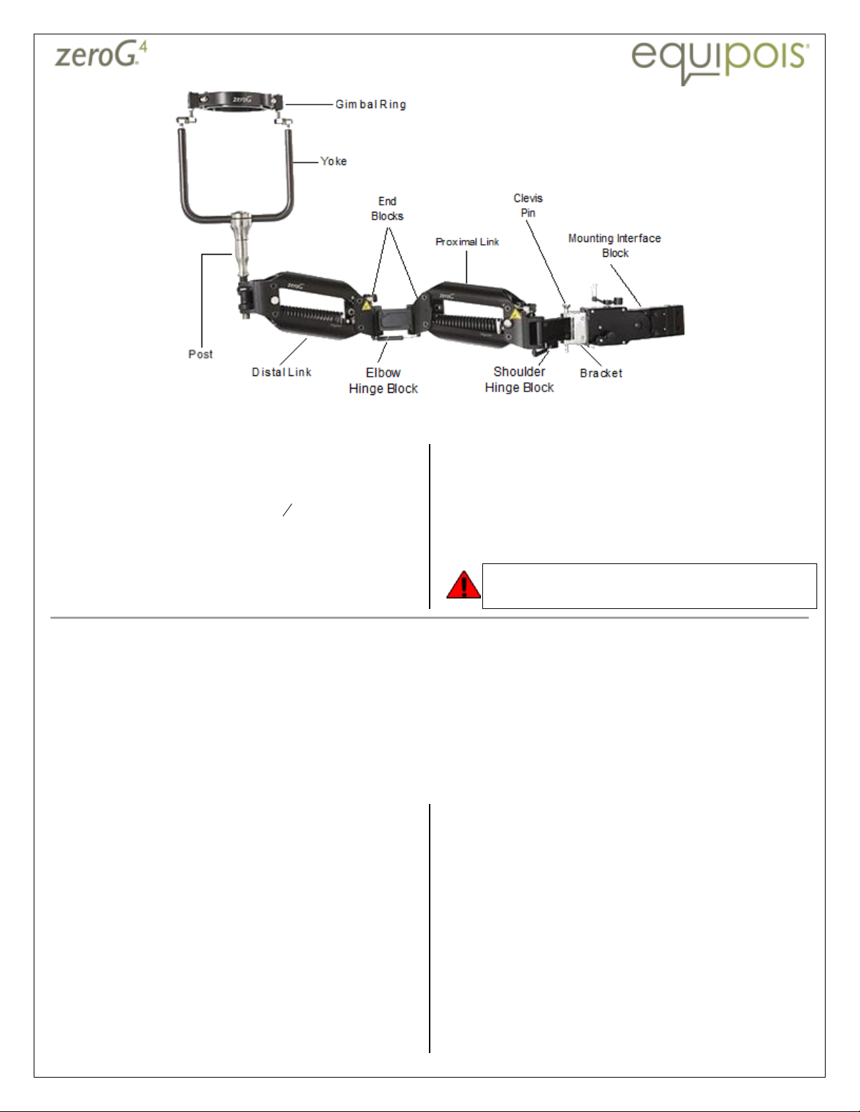
Mounting the payload
1. Extend the arm or dock it securely. Do not mount or
dismount the payload when you are using the built-in
dock, unless there is no alternative.
2.
Loosen the two-piece collar with a
32
3
-inch llen
wrench
.
3. If this is a top-mount (shown), position the collar for the
desired height and tighten it.
4. If this is an underslung mount, remove the collar.
5. Insert the gimbal post into the socket at the end of the
arm.
6. If this is an underslung mount, have an assistant help
you position and tighten the collar.
7. Dress hoses and cables with zip-ties to the gimbal post
and the elbow hinge block.
DO NOT MOUNT ND DISMOUNT THE P YLO D
WHEN THE BUILT
-
IN DOCK IS IN USE
.
Adjusting the rest position
The dynamic and preset mounting interface blocks have different adjustment mechanisms, but the process of adjustment
is the same. Pitch adjustment moves the bracket up and down, in a head-nodding motion. Roll adjustment rotates the
bracket, as viewed from the front.
1. With the tool mounted and the arm undocked, let the arm extend toward the work area and, without letting go com-
pletely, let it move freely.
2. If the arm consistently drifts to the same side, adjust the pitch down and the roll away from the direction of drift.
3. If the arm drifts to either side, adjust the pitch down. Pitch should be as far up as possible without causing the arm to
be unstable.
Adjust a dynamic mounting interface
block
The block can be adjusted with the arm extended, as you
move around, to compensate for flex in the support or for
uneven floors.
• djust pitch by turning the crank on the top of the
mounting interface block. Cranking clockwise pitches
the bracket down.
• djust roll by turning the crank on the side of the block.
Cranking clockwise rolls the bracket counterclockwise.
Adjust a preset mounting interface
block
djustments are made with pairs of set screws.
1. To adjust pitch, use the screws on the back of the block:
a. If necessary, unload the bottom set screw by moving
the tool toward the back of the mounting interface
block.
b. Back off one of the screws to create slack in the direc-
tion you want to move the bracket
c. Tighten the other screw to move the bracket.
2. djust roll with the side screws, and unload the set
screw by moving the tool to one side or the other.
3. Tighten both screws in each pair snugly.

Arm Operator’s Reference
zeroG and Equipois are registered trademarks of Equipois Inc. of Los Angeles, CA
.
101
-
115 Rev A
Safety notes
The zeroG arm is made to flex effortlessly and follow you as you work, and it uses very strong springs to support the payl-
oad. Because the arm can move very fast and powerfully on its own, you must take care to keep it under control.
L
EANING OR HANGING
Do not lean or hang from the
zeroG
arm.
P
INCH POINTS
• Keep fingers, clothing, tools, work pieces, and other items away from the labeled pinch points on
the zeroG arm.
• During operation, use the tool’s grips and avoid touching the arm, except the adjustment cranks of
the dynamic mounting interface block.
• When the arm is not docked, handle it only by the end blocks and the adjustment knobs.
• Use of protective covers is recommended.
M
AXIMUM
L
OAD
Maximum payload capacity is 36 lbs., including the gimbal-tool-post assembly and cables and hoses.
Do not load more than 36 lbs. on your zeroG arm.
E
NVIRONMENTAL
E
LEMENTS
Keep liquids, gels, dust, paint, and debris away from the
zeroG
arm, or protect arm segments with
disposable or permanent arm covers from Equipois.
D
OCKING
&
POSITIONING
Dock the zeroG arm in a horizontal position when it is not in use. Do not leave the
zeroG
arm free or
floating where it can easily swing or move.
U
NDOCKING AN
UNLOADED
zeroG
ARM
An unloaded
zeroG
arm
RISES FORCEFULLY
and can cause injury if it is released suddenly from its docked
position. Never undock a zeroG arm unless it is loaded with its intended payload or the spring tension
is balanced by restraints or a counter weight.
P
AYLOAD REMOVAL
Do not mount or dismount the payload from the
zeroG
arm when the built-in dock is in use.
Adjust lift
Lift is the force that the links of the arm exert to hold up
the weight of the tool. The usual lift floats the tool with
the links almost level. Some operators prefer to set the
links at a higher angle, to help with the work. To change
the lift:
1. With the payload in place, extend the arm.
2. Move the payload so that the spring of the forearm link
is perpendicular to the adjusting mechanism. The link
should be slanting at about 5° above level and the Lift
knob should turn easily.
3. Turn the Lift knob until the link balances at the 5° slant:
a. Turn the knob clockwise to increase lift, if you lifted
the payload.
b. Turn the knob counterclockwise to decrease lift, if
you pulled the payload down.
4. In the same way, adjust the upper-arm link so it bal-
ances at the 5° slant.
5. When the links are adjusted, carefully move the tool up
and down to the full extent of its range. The links
should track smoothly as you move the tool up and
down.
6. Hold the arm pointed toward the work area and with-
out letting go completely, let it move freely:
a. If the arm drifts consistently to one side, adjust the
pitch down and the roll away from the direction of
drift.
b. If the arm drifts to either side, adjust the pitch down.
7. If a link locks in the full up or down position, adjust the
rate.
Hint: Adjust lift for a lighter tool before you remove the
heavier tool.
Adjust Rate
The arm is isolastic, that is, it requires almost the same
force to move it up and down throughout its vertical
range. As the tool moves, the arm compensates for
changes in the links’ angles. This compensation is called
rate. The usual setting is to have the Rate knob turned ful-
ly counterclockwise for maximum isolasticity. To change
the rate:
1. Raise the link to the full up position.
2. To decrease isolasticity and make it harder for the op-
erator or the arm to raise or lower the tool, turn the
Rate knob clockwise.
3. To increase isolasticity and make it easier to move the
tool through the full range of vertical motion, turn the
Rate knob counterclockwise.
4. When the link no longer locks up, adjust the lift so the
arm floats in the proper attitude.
Lift knob with R te
knob behind
Table of contents
Other Equipois Tools manuals


