AIRLESSCO SureStripe 4000 User manual

SERVICE/OPERATION
MANUAL
Form No. 001-682
SEP06

Table of Contents
INTRODUCTION
SureStripe 4000 Specications 1
Safety Warnings 2
GETTING STARTED
Flushing 7
Setting Up 8
Pressure Relief Procedure 9
Daily Maintenance 9
Starting Up 10
Striping Operation 12
Striping Tip Guide 13
REPAIRS/MAINTENANCE
INSTRUCTIONS
Spray Gun Operation 14
Spray Gun Troubleshooting 15
Field Troubleshooting 16
Servicing the Fluid Pump 17
Servicing the Piston Rod 18
Servicing the Suction Assembly 18
Packing Replacement 19
Electrical Control Board
Replacement 21
Pressure Calibration on
the Electrical Control Board 21
Clutch Replacement 22
Troubleshooting Clutch Does
Not Engage 23
AIRLESSCO BY DUROTECH CO.
5397 N. Commerce Ave.,Moorpark, CA 93021
Phone: 805-523-0211 FAX: 805-523-1063
Email: [email protected]
SPECIFICATIONS SUBJECT TO CHANGE WITHOUT NOTICE.
Copyright © 2005-2006, All rights reserved.
PRODUCT DIAGRAMS &
PARTS LISTS
Gun Mount Assembly 24
Gearbox Assembly 25
Suction Assembly 25
Frame Assembly Diagram 26
Frame Assembly Parts List 27
www.airlessco.com

Before operating this unit, read and follow all safety warnings and instructions
related to the usage of this equipment. READ, LEARN, and FOLLOW the
Pressure Relief Procedure on Page 9 and understand all warnings on
pages 2 thru 6.
IMPORTANT WARNING !!
HANDLE THIS UNIT AS YOU WOULD A LOADED FIREARM!!
High pressure spray can cause extremely serious injury.
OBSERVE ALL WARNINGS!
All Service Procedures to be performed by an Authorized Airlessco Service Center ONLY.
NO MODIFICATIONS or alterations of any Airlessco Equipment or part is allowed.
Introduction
1
The 4000 is the compact piston pump striper that
delivers the professional results and range of features
needed by pavement striping contractors—and it’s an
incredible value!
It’s based on our proven LP Piston Pump used daily
by thousands of painting contractors. The large one-
piece piston along with Airlessco's patented triple-life
packing system results in reduced maintenance,
lower operating costs, and longer equipment life. A
clutch actuated .8 gpm paint system features an
electronic pressure control system.
The 4000 is powered by a dependable 4 hp Honda GX
series commercial OHV 4-cycle engine. It’s built on
a small, compact frame, that’s easy to use, and quick
to clean. Designed-in balance & light weight make it
ideal for one-man operation. Foot operated parking
brake holds machine on inclines.
Our 008 Silver Contractor spray gun can spray wtih an
up to .029” tip. It mounts on any corner, and has a
quick release for painting parking curbs or pavement
using stencils. It features a tungsten carbide ball and
seat, the “No Drips” REV-GUARD™ base, and our
patented REV-TIP™ reversible tips that clear clogs
literally in a snap.
INTRODUCTION
Power Honda 4 HP with Oil Alert®
Pump “LP” Piston, Triple-Life Packings
Electronic pressure control system
Annual Usage up to 2500 gallons
Max Pressure 0-3000 PSI
Max Output .8 GPM, 3 Liters/min.
Max Tip Size .029”
Frame Welded box steel, powder coated
Shipped Complete:
Part # 305-227 SURE STRIPE 4000 with
spray gun and 50’ of hose.

TIP GUARD
ALWAYS have the tip guard in place on the spray gun while spraying. The tip guard alerts you to the injection hazard and helps
prevent accidentally placing your ngers or any part of your body close to the spray tip.
SPRAY TIP SAFETY
Use extreme caution when cleaning or changing spray tips. If the spray tip clogs while spraying, engage the gun safety latch
immediately.
• ALWAYS follow the PRESSURE RELIEF PROCEDURE and then remove the spray tip to clean it.
• NEVER wipe off build up around the spray tip.
• ALWAYS remove tip & tip guard to clean AFTER pump is turned off and the pressure is relieved by following the
PRESSURE RELIEF PROCEDURE.
KEEP CLEAR OF MOVING PARTS
Keep clear of moving parts when starting or operating the sprayer. Do not put your ngers into any openings to avoid
amputation by moving parts or burns from hot parts.
Precaution is the best insurance against an accident.
When starting the engine, maintain a safe distance from moving parts of the equipment.
Before adjusting or servicing any mechanical part of the sprayer, follow the PRESSURE RELIEF PROCEDURE, and remove
the ignition cable from the spark plug to prevent accidental starting of the sprayer.
ALWAYS INSPECT SPRAYING AREA
• ALWAYS keep spraying area free from obstructions.
• ALWAYS make sure area has good ventilation to safely remove vapors and mists.
• NEVER keep ammable material in spraying area.
• NEVER spray in vicinity of open ame or other sources of ignition.
SPRAY GUN SAFETY
• ALWAYS set safety lock on the gun in "LOCKED" position when not in use and before servicing or cleaning.
• NEVER remove or modify any part of the gun.
• ALWAYS REMOVE SPRAY TIP when cleaning. Flush unit with LOWEST POSSIBLE PRESSURE.
• ALWAYS check operation of all gun safety devices before each use.
• Be very careful when removing the spray tip or hose from gun. A plugged line contains uid under pressure. If the tip or
line is plugged, follow the PRESSURE RELIEF PROCEDURE as outlined on page 9.
Safety Warnings
Keep all labels on the unit clean and readable. Replacement labels are available from the manufacturer.
LABELING
Hazardous uid or toxic fumes can cause serious injury or death if splashed in eyes or on skin, inhaled or swallowed. Know
the hazards of the uid you are using. Store & dispose of hazardous uids according to manufacturer, local, state & national
guidelines. ALWAYS wear protective eye wear, gloves, clothing and respirator as recommended by uid manufacturer.
TOXIC FLUID HAZARD
2

Safety Warnings
Fluids under high pressure from spray or leaks can penetrate the skin and cause extremely serious
injury, including the need for amputation.
• NEVER point the spray gun at anyone or any part of the body.
• NEVER put hands or ngers over the spray tip. Do not use a rag or any other material over your ngers. Paint will
penetrate through material and into the hand.
• NEVER try to stop or deect leaks with your hand or body.
• NEVER try to "blow back" paint, this is not an air spray sprayer.
• ALWAYS have gun tip guard in place when spraying.
• ALWAYS lock gun trigger when you stop spraying.
• ALWAYS remove tip from the gun to clean it.
• ALWAYS follow the PRESSURE RELIEF PROCEDURE, as shown on page 9, before cleaning or removing the
spray tip or servicing any system equipment.
• ALWAYS Be sure equipment safety devices are operating properly before each use.
• ALWAYS tighten all uid connections before each use.
MEDICAL TREATMENT
If any uid appears to penetrate your skin, get EMERGENCY CARE AT ONCE. DO NOT TREAT AS A SIMPLE CUT.
* Go to an emergency room immediately.
* Tell the doctor you suspect an injection injury.
* Tell him what kind of material you were spraying with and have him read NOTE TO PHYSICIAN.
HIGH PRESSURE SPRAY CAN CAUSE EXTREMELY SERIOUS INJURY.
OBSERVE ALL WARNINGS. THIS SPRAYER IS FOR PROFESSIONAL USE ONLY.
MEDICAL ALERT - Airless Spray Wounds NOTE TO PHYSICIAN:
If any uid appears to penetrate your skin, get Injection in the skin is a traumatic injury.
EMERGENCY MEDICAL CARE AT ONCE. DO It is important to treat the injury surgically
NOT TREAT AS A SIMPLE CUT. Tell the doctor as soon as possible. DO NOT DELAY treatment
exactly what uid was injected. Have him read to research toxicity. Toxicity is a concern with
the following "NOTE TO PHYSICIAN". some exotic coatings injected directly into the
bloodstream. Consultation with a plastic surgeon or
reconstructive hand surgeon may be advisable.
INJECTION HAZARD
GENERAL PRECAUTIONS
• NEVER alter equipment in any manner. • NEVER smoke while in spraying area.
• NEVER spray highly ammable materials. • NEVER use around children.
• NEVER allow another person to use sprayer unless they are thoroughly instructed on safety use and
given this operators manual to read.
• ALWAYS wear a spray mask, gloves and protective eye wear while spraying.
• ALWAYS ensure re extinquishing equipment is readily available and properly maintained.
NEVER LEAVE SPRAYER UNATTENDED WITH PRESSURE IN THE SYSTEM. FOLLOW PRESSURE RELIEF
PROCEDURES ON PAGE 9.
3

AVOID COMPONENT RUPTURE
This sprayer operates at 3000 psi (205 bar). Always be sure that all components and accessories have a
maximum working pressure of at least 3000 psi to avoid rupture which can result in serious bodily injury
including injection and property damage.
• NEVER leave a pressurized sprayer unattended to avoid accidental operation of it which could result in serious
bodily injury.
• ALWAYS follow the PRESSURE RELIEF PROCEDURE whenever you stop spraying and before adjusting,
removing or repairing any part of the sprayer.
• NEVER alter or modify any part of the equipment to avoid possible component rupture which could result in
serious bodily injury and property damage.
• NEVER use weak, damaged or non-conductive paint hoses. Do not allow kinking or crushing of hoses or allow
it to vibrate against rough, sharp or hot surfaces. Before each use, check hoses for damage and wear and ensure
all uid connections are secure.
• REPLACE any damaged hose. NEVER use tape or any device to mend the hose.
• NEVER attempt to stop any leakage in the line or ttings with your hand or any part of the body. Turn off the
unit and release pressure by following PRESSURE RELIEF PROCEDURE on page 9,.
• ALWAYS use approved high pressure ttings and replacement parts.
• ALWAYS ensure re extinquishing equipment is readily available and properly maintained.
Safety Warnings
GROUNDING
Ground the sprayer and other components in the system to reduce the risk of static sparking, re or explosion which can
result in serious bodily injury and property damage.
Always ground all of these components:
• Sprayer: Be sure grounding chain (supplied) is in contact with the ground.
• Fluid Hose: use only grounded hoses.
• Spray gun or dispensing valve: grounding is obtained through connection to a properly
grounded uid hose and pump.
• Object being sprayed: according to your local code.
• All solvent pails used when ushing should only be metal pails which are conductive.
Once each week, check electrical resistance of hose (when using multiple hose assemblies, check overall resistance of
un-pressurized hose must not exceed 29 megohms (max) for any coupled length or combination of hose lengths. If hose
exceeds these limits, replace it immediately.
Never exceed 500 Ft. (150 m.) overall combined hose length to assure electrical continuity.
Do not use halogenated solvents in this system. Most airless guns have aluminum parts and may
explode. Cleaning agents, coatings, paints or adhesives may contain halogenated hydrocarbon
solvents. DON'T TAKE CHANCES! Consult your material suppliers to be sure.
Some of the most common of these solvents are:
Carbontetrachloride, Chlorobenzene, Dichloroethane, Dichloroethyl Ether,
Ethylbromide, Ethylchloride, Tethrachloethane.
Alternate valves & guns are available if you need to use these solvents.
4

Gasoline & its vapors are extremely
ammable & explosive.
Fire or explosion can cause severe burns or death.
WHEN ADDING FUEL
• Turn engine OFF and let engine cool at least 2
minutes before removing gas cap.
• Fill fuel tank outdoors or in well ventilated area.
• Do not overll fuel tank. Fill tank to approximately
1 inches below top of neck to allow for fuel
expansion.
• Keep gasoline away from sparks, open ames, pilot
lights, heat and other ignition sources.
• Check fuel lines, tank, cap and ttings frequently for
cracks or leaks. Replace if necessary.
PREVENT STATIC SPARKING FIRE/ EXPLOSIONS
ALWAYS be sure all equipment and objects being sprayed are properly grounded. Always ground sprayer, paint bucket and
object being sprayed. See "grounding" on page 4 for detailed grounding information.
Vapors created when spraying can be ignited by sparks. To reduce the risk of re, always locate the sprayer at least 20 feet (6
m.) away from the spray area. Do not plug in or unplug any electrical cords in the spray area, this can create sparks when there
is any chance of igniting vapors still in the air. Follow the coating & solvent manufacturers safety warnings and precautions.
Use only conductive uid hoses for airless applications. Be sure gun is grounded through hose connections. Check ground
continuity in hose & equipment. Overall (end to end) resistance of un-pressurized hose must not exceed 29 megohms for any
coupled length or combination of hose length. Use only high pressure airless hoses with static wire approved for 3000 psi.
WHEN SPRAYING & CLEANING WITH FLAMMABLE PAINTS OR PAINT THINNERS:
• When spraying with ammable liquids, unit must be located a minimum of 25 feet away from spraying area
in a well ventilated area. Ventilation must be sufcient enough to prevent the accumulation of vapors.
• To eliminate electrostatic discharge, ground the spray unit, paint bucket and spraying object. Use only high
pressure airless hoses approved for 3000 psi which is conductive.
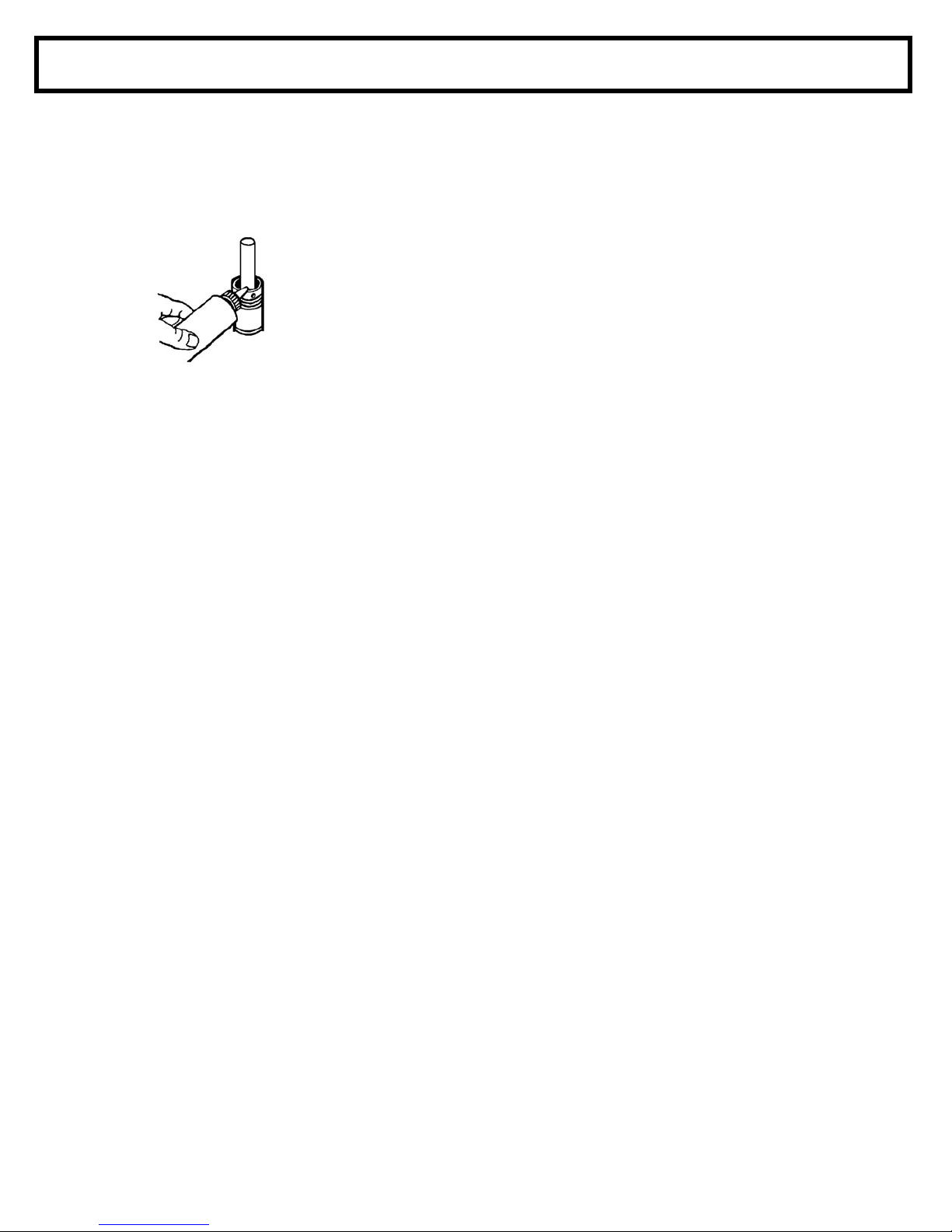
• Remove spray tip before cleaning gun and hose. Make contact of gun with bucket and spray without the tip in
a well ventilated area, into the grounded steel bucket.
• Never use high pressure in the cleaning process. USE MINIMUM PRESSURE.
• Do not smoke in spraying/cleaning area.
GAS ENGINE PRECAUTIONS
Important: United States Government safety standards have been adopted under the Occupational
Safety & Health Act. These standards, particularly the General Standards, Part 1910, & the
Construction Standards, part 1926 should be consulted.
FLUSHING
Reduce risk of injection injury, static sparking or splashing by following the specic cleaning
procedure on page 5.
• ALWAYS follow the PRESSURE RELIEF PROCEDURE on page 9.
• ALWAYS remove the spray tip before ushing. Hold a metal part of the gun rmly to the side of a metal pail and
use the lowest possible uid pressure during ushing.
• NEVER use cleaning solvents with ash points below 140º F. Some of these are: acetone, benzene, ether,
gasoline and naphtha. Consult your supplier to be sure.
• NEVER smoke in the spraying/cleaning area.
Safety Warnings
WHEN STARTING ENGINE
• Make sure spark plug, mufer, fuel cap and air cleaner
are in place.
• Do not crank engine with spark plug removed.
• If fuel spills, wait until it evaporates before starting
engine.
• If engine oods, set choke to OPEN/RUN
position, place throttle in FAST and crank until
engine starts.
WHEN OPERATING EQUIPMENT
• Do not tip engine or equipment at angle which
causes gasoline to spill.
• Do not choke carburetor to stop engine.
WHEN TRANSPORTING EQUIPMENT
• Transport with fuel tank EMPTY or with fuel shut-off
valve OFF.
5

Engines give off carbon monoxide, an odorless,
colorless, poison gas.
Breathing carbon monoxide can cause nausea,
fainting or death.
• Start and run engine outdoors.
• Do not start or run engine in enclosed area, even if doors or
windows are open.
Running engines produce heat. Engine parts,
especially mufers, become extremely hot.
Severe thermal burns can occur on contact.
Combustible debris, such as leaves, grass, brush,
etc. can catch re.
• Allow mufer, engine cylinder and ns to cool before
touching.
• Remove accumulated combustibles from mufer area and
cylinder area.
• Install and maintain in working order a spark arrester
before using equipment on forest covered, grass covered
and brush covered unimproved land. The state of
California requires this (Section 4442 of the California
Public Resources Code). Other states may have similar
laws. Federal laws apply on federal land.
Unintentional sparking can result in re
or electric shock.
Unintentional start up can result in entanglement,
traumatic amputation, or lacerations.
BEFORE PERFORMING ADJUSTMENTS OR REPAIRS
• Disconnect spark plug wire and keep it away from
spark plug.
• Disconnect battery at negative terminal (only
engines with electric start).
WHEN TESTING FOR SPARK
• Use approved spark plug tester.
• Do not check for spark with spark plug removal.
WHEN STORING GASOLINE OR EQUIPMENT WITH FUEL
IN TANK
• Store away from furnaces, stoves, water heaters and
other appliances that have pilot lights or other ignition
source. They can ignite gasoline vapors.
Starting engine creates sparking.
Sparking can ignite nearby ammable gases.
Explosion and re could result.
• If there is natural or LP gas leakage in area, do not
start engine.
• Do not use pressurized starting uids because vapors
are ammable.
Rapid retraction of starter cord (kickback) will pull
hand and arm toward engine faster than you can let go.
Broken bones, fractures, bruises or sprains could result.
• When starting engine, pull cord slowly until resistance is
felt, then pull rapidly.
• Remove all external equipment/engine loads before starting
engine.
• Direct coupled equipment components such as, but not
limited to, blades, impellers, pulleys, sprockets, etc. must
be securely attached.
Rotating parts can contact or entangle hands, feet,
hair, clothing or accessories.
Traumatic amputation or severe laceration can result.
• Operate equipment with guards in place.
• Keep hands and feet away from rotating parts.
• Tie up long hair and remove jewelry.
• Do not wear loose tting clothing, dangling drawstrings or
items that could become caught.
Safety Warnings
6

1. New Sprayer
Your Airlessco unit was factory tested in an antifreeze solution which was left in the pump.
Before using oil-base paint, ush with mineral spirits only. Before using water-base paint
ush with soapy water, then do a clean water ush.
2. Changing Colors
Flush with a compatible solvent such as mineral spirits or water.
3. Changing from water-base to oil-base paint
Flush with soapy water, then mineral spirits.
4. Changing from oil-base to water-base paint
Flush with mineral spirits, followed by soapy water, then do a clean water ush.
5. Storage
Oil-base paint: Flush with mineral spirits.
Water-base paint: Flush with water, then mineral spirits and leave the pump, hose and gun
lled with mineral spirits. For longer storage (and in areas where there is the potential for
freezing temperatures), use mixture of mineral spirits and motor oil (half & half). Shut off
the sprayer, follow Pressure Relief Procedure on page 9 to relieve pressure and make sure
prime valve is left OPEN.
6. Start up after storage
Before using water-base paint, ush with soapy water and then do a clean water ush. When
using oil-base paint, ush out the mineral spirits with the material to be sprayed.
Flushing
IMPORTANT: Read Prior to Using Your Sprayer
7

8
1. Keep the displacement pump packing nut/wet cup lubricated with Airlessco TSO
(Throat Seal Oil) at all times. The TSO helps protect the rod and the packings.
Daily Maintenance
Airlessco Throat Seal Oil
6 ounce bottle Part # 188-187
1 quart bottle Part # 188-392
2. Inspect the packing nut daily. Your pump has Airlessco’s patented Triple Life Packing System.
Packing life will be extended a minimum of three times if the
following "Packing Adjustment" procedure is followed:
If seepage of paint into the packing nut and/or movement of the piston upward is found (while not
spraying), the packing nut should be tightened enough to stop leakage only, but not any tighter.
Overtightening will damage the packings and reduce the packing life.
3. Check suction nut daily.

9
Pressure Relief Procedure
IMPORTANT!
To avoid possible serious body injury, always follow this procedure whenever the
sprayer is shut off, when checking it, when installing, changing or cleaning tips,
whenever you stop spraying, or when you are instructed to relieve the pressure.
1. Engage the gun safety latch. Refer to the
separate instruction manual provided with
your gun on its safety features and how to
engage safety latch.
4. Turn Prime/Pressure Relief Valve (PR Valve)
to the open (priming) position to relieve
residual uid pressure.
There will be a wider gap between valve
handle and cam body when in open
position. In the closed position there is
only a very slight gap.
.
Note: The valve handle can move both
clockwise and counter clockwise and can
face different directions.
2. Turn the unit off.
3. Disengage the gun safety latch and trigger
the gun to relieve residual uid pressure.
Hold metal part of the gun in
contact with grounded metal pail.
USE MINIMUM PRESSURE !
5. Re-engage gun safety latch and
close Prime/Pressure Relief Valve.
If the SPRAY TIP OR HOSE IS CLOGGED, follow Step 1 through 5 above. Expect paint
splashing into the bucket while relieving pressure during Step 4.
If you suspect that pressure hasn't been relieved due to damaged Prime/Pressure
Relief Valve or other reason, engage the gun safety latch and take your unit to an
authorized Airlessco Service Center.

10
Starting Up
4. Adjusting the Pressure
a. Turn the Pressure Control Knob Clockwise to
increase pressure and counterclockwise to decrease
pressure.
b. Always use the lowest pressure necessary to
completely atomize the material.
Note: Operating the sprayer at higher pressure
than needed, wastes material, causes early tip
wear, and shortens sprayer life.
c. If more coverage is needed, use a larger tip rather
than increasing the pressure.
d. Check the spray pattern. The tip size and angle
determines the pattern width and ow rate.
1. Learn the Functions
of the Controls.
2. Prepare the Material
a. Prepare the material according to the material
manufacturer's recommendations.
b. Place the suction tube into the material
container.
PRESSURE CONTROL KNOB is used to adjust
pressure. Turn clockwise (CW) to increase pressure
and counterclockwise (CCW) to
decrease pressure.
PRIME/PRESSURE (PR) RELIEF VALVE is used to
prime pump and to relieve pressure from gun, hose and tip.
Prime/Pressure Relief Valve (Prime/PR Valve)
Used to relieve pressure from gun, hose & tip and to prime
the unit when in OPEN position. (It is in open position
when there is a wider gap
between valve handle and
cam body)
When in CLOSED position,
there is only a very slight gap
between handle & body.
When closed the system is
pressurized. Handle as a loaded rearm!
3. Starting the Sprayer
a. Prime/PR Valve must be "OPEN" in the priming
position.
b. When you have ensured that the gun safety latch
is engaged, attach tip and safety guard.
c. Turn the engien ON/OFF switch to the
"ON" position.
d. Turn Pressure Control Knob clockwise to prime
the pump.
e. After the pump is primed, turn Prime/PR Valve to
the "Closed" position.
f. Turn Pressure Control Knob to the desired spray
pressure.
g. Disengage the gun safety latch and you are
ready to spray.

11
When you spray into the paint bucket,
always use the lowest spray pressure
and maintain rm metal to metal contact
between gun and container.
To stop the unit in an emergency, turn the
engine off. Then relieve the uid pressure
in the pump and hose as instructed in the
Pressure Relief Procedure.
Follow the "Pressure Relief Procedure".
To reduce the risk of injection, never hold
your hand, body, ngers or hand in a rag
in front of the spray tip when cleaning
or checking for a cleared tip. Always
point the gun toward the ground or into a
waste container when checking to see if
the tip is cleared or when using a
self-cleaning tip.
5. When Shutting off the Sprayer
a. Whenever you stop spraying, even for a short break,
follow the "Pressure Relief Procedure".
b. Clean the tip & gun as recommended in the seperate
Gun Manual supplied with the gun/
c. Flush the sprayer at the end of each work day, if the
material you are spraying is water-based, or if it could
harden in the sprayer overnight. See "Flushing". Use a
compatible solvent to ush, then ll the pump and hoses
with an oil based solvent such as mineral spirits.
d. For long term shutdown or storage, refer to the
"Flushing" section of this manual.
Be sure to relieve pressure in
the pump after lling with Airlessco
Pump Conditioner.
Avoiding Tip Clogs
There is an easy way to keep the outside of the
tip clean from material build up:
Every time you stop spraying, for even a minute,
lock the gun and submerge it into a small bucket
of thinner suitable for the material sprayed.
Thinner will dissolve the buildup of paint on the
outside of tip, tip guard and gun much more
effectively if the paint doesn't have time to dry
out completely.
Starting Up

Striping Operation
1. Choose handle location
The choices are, installing the handle opposite
of the single wheel assembly (standard set up)
or placing the handle directly over the single
wheel assembly. The handle location is really
a matter of personal preference, however
having the handle away from the single wheel
assembly allows for easier loading/unloading
from a van.
2. Choose the gun arm position
There are multiple holes in the frame for
mounting the gun arm. In a standard set up
(handle away from the single wheel assembly),
the gun arm would be mounted in one of the
two mounting holes near the single wheel. This
allows for an easier visual check for straight
line striping and for basic arc striping. The
mounting holes under the handle are usually
used when the handle has been placed over
the single wheel. Experiment with different
combinations to nd the set up that you prefer.
3. Setting up the gun
a. Ensure that a striping tips is in the guns.
b. Pick a tip size for the desired line width.
Example: a 217ST tip for a four inch line.
c. Place gun into the gun holder, so that the
top of the taper on the gun handle is ush
with the edge of the gun holder.
d. Set gun height for the desired line width.
Adjust height by loosening the small black
handle on the gun holder assembly and
slide the gun arm to the correct height. Now
tighten the handle. This will require some
experimentation to nd the correct height.
It is suggested that tape, or some other
method is used to mark the height of
commonly used settings.
e. Attach the swivel heads to the gun if
painting curbs or wide stripes.
f. Angle the gun slightly forward. This
allows the spray pressure from the gun to
help blow dirt and debris out of the path of
the new stripe.
4. Cable Tension Adjustment
Once the handle and gun arm assemblies are set up to
the preferred position, pressurize the unit and trigger
the gun to ensure that they activate and release
correctly. If not, adjust the cable tension as follows:
a. Locate the adjustment knobs on the base of the
gun trigger, where the cable connects to the gun
trigger assembly.
b. Loose the locking nut & move the adjusting screw
until the slack has been removed from the cable.
c. Tighten locking nut and retest gun triggers for
proper function.
NOTE: There is additional cable adjustment
where the cable attaches to the gun
holder assembly. Use only if the gun
trigger adjustment is insufcient.
5. Miscellaneous Operations
a. CURBS: Adjust gun to desired height and turn
swivel head towards curb.
b. WIDE STRIPES: Install wider fan striping tips
and raise the gun height to achieve the desired
width line.
c. STENCILS: Install standard spray tip. Remove
gun from the gun holder and spray out the
stencils.
d. STANDARD PAINTING: Same as stencils, but
use additional paint hose as required.
12
Inserting REV-TIP™ & seal into REV-GUARD™

STRIPING TIP - ORIFICE SIZE (Inches)
in (mm) .009 .011 .013 .015 .017 .019 .021 .023 .025 .027 .031 .035
1-2 25-51 113ST 115ST 117ST 119ST
2-4 51-102 215ST 217ST 219ST 221ST
4-6 102-152 315ST 317ST 319ST 321ST 323ST
6-8 152-203 415ST 417ST 419ST 421ST
Striping Paint
Striping Tip Guide
STRIPING TIPREGULAR PAINTING SPRAY TIP
UNIFORM PATTERN
LIGHTHEAVY
Striping Tips (orange handle) should not be used for regular spraying. They are designed for a single
pass application, while spray tips (black handle) are designed for the 1/3 overlap technique used for
spray painting.
Spray Tip Replacement: During use high pressure will cause the orifice to grow larger and more round. This
destroys the efficiency of the pattern, wasting your material. It can also leave tailing or two heavy lines on the
outside of the pattern.
Oil Base Oil Base Latex Latex Latex Latex LatexLatex
Rev-Tip
TM
for Striping
Fan Width (6” from surface)
REV-GUARD
TM
Super Compact
P.N. 561-001
11/16-16 “F” Thread. Fits:
Airlessco, and some ASM,
Wagner, and Campbell Hausfeld.
P.N. 561-002
7/8-14 “G” Thread.
Fits some: Graco, Wagner,
Titan, Airlessco.
562-215ST
Striping REV-TIP
TM
Orifice Size
1/2 Fan Width in inches
Sample:
REV-TIP
TM
for Striping
P.N. 562-xxxST
Includes Rev-Tip
TM
, Metal Seal
& O-Ring Seal.
(water @ 2000psi, 138 bar)
(latex paint @ 2000psi,
138 bar/1.36 spec. gr.)
*Pump will support tip worn to next larger size.
Water Flow Rate (gpm) .12 .18 .24 .31 .38 .47 .57 .67 .77 1.03 1.31
(lpm) .49 .69 .91 1.17 1.47 1.79 2.15 2.54 2.96 3.90 4.98
Paint Flow Rate (gpm) .10 .15 .21 .27 .33 .40 .49 .58 .66 .88 1.12
(lpm) .38 .57 .79 1.02 1.25 1.51 1.85 2.20 2.50 3.33 4.24
Pump Minimum (gpm) .25 .25 .33 .40 .50 .60 .75 .88 1.0 1.25 1.5
Output* (lpm) 1.0 1.0 1.25 1.5 1.9 2.3 2.8 3.3 3.8 4.7 5.7
LIGHT
13
Latex Latex

Spray Gun Operation
SPRAY GUN
Attach spray gun to airless unit and tighten ttings securely.
Set the gun safety latch. (Also may be called gun safety
lock, or trigger lock)
* The gun safety latch should always be set when the gun is
not being triggered.
Read all warnings and safety precautions supplied with the
spray gun and in product manual.
SPRAY TIP ASSEMBLY
1. Be sure the pressure relief procedure is followed
before assembling tip and housing to the gun.
2. Insert REV-TIP™ cylinder into the REV-GUARD™
(guard housing assembly).
3. Guide the metal seat into REV-GUARD™ (guard
housing assembly) through the retaining nut and turn
until it seats against the cylinder.
4. Insert the O-Ring gasket onto the metal seat so that it
ts into the grooves.
5. Finger tighten REV-GUARD™ retaining nut onto the gun.
6. Turn guard in the desired position.
7. Completely tighten the retaining nut.
O-Ring Gasket
Metal Seat
Retaining Nut
Spray Position Shown
Reverse to
Unplug
REV-GUARD™
Guard Housing Assembly
TO REMOVE CLOGS FROM SPRAY TIP
1. Lock gun safety latch.
2. Turn REV-TIP™ handle 180 degrees.
3. Disengage trigger lock and trigger gun into
the pail.
4. If the REV-TIP™ handle appears locked
(resists turning), loosen the retaining nut. The
handle will now turn easily.
5. Engage gun safety latch and return handle to
the spray position.
Retaining Nut
CLEANING SPRAY GUN
CLEANING FILTER IN GUN HANDLE
Immediately after the work is nished, ush the gun out
with a solvent. Brush pins with solvent and oil them
lightly so they will not collect dried paint.
To clean the lter, use a brush dipped in an appropri-
ate solvent. Change or clean lters at least once a day.
Some types of latex may require a lter change after
four hours of operation.
CLOGGED FLAT TIP
Should the spray tip become clogged, relieve
pressure from hose by following the "Pressure Re-
lief Procedure." Secure gun with the safety latch,
take off guard, take out the tip, soak in appropriate
solvent & clean with a brush. (Do not use a needle
or sharp pointed instrument to clean the tip. The
tungsten carbide is brittle and can chip.)
™
14
Reversible
Spray Tip
Tip Guard
Trigger Guard
MAJOR COMPONENTS OF SPRAY GUN &
REVERSIBLE REV-TIP™
Gun Handle. Unscrew
from gun head to service
lter inside.
Gun Safety
Latch or Lock
Press up here & pull gently
to remove trigger guard
REV-TIP™
Part # 561-026
Part # 561-029
Part # 561-XXX
G Thread 7/8" 561-002
F Thread 11/16" 561-001

Spray Gun Troubleshooting
15
Problem Cause Correction
Coarse Spray, Spotty Pattern Pressure setting low
Irratic spray gun/hand motion
Increase pressure setting
Use a steady, parallel pass
Excessive Overspray (Fogging) Pressure setting high
Paint over thinned/reduced/cut
Reduce pressure setting
Use less thinner/water/reducer
Spray Pattern Excessively Wide Incorrect fan width selection Select narrower fan width tip*
Spray Pattern Excessively Narrow Incorrect fan width selection Select wider fan width tip*
Excessive Paint Delivery
Paint Film Runs/Sags
Large tip orice for application
Paint over thinned/reduced/cut
Excessive pressure
Spray gun/hand speed slow
Select smaller tip orice*
Use less thinner/water/reducer
Reduce pressure setting
Increase pass speed
Spray Pattern Rounded and Heavy:
Pump Does Not Keep Up
Tip worn beyond use Replace with new tip*
Spray Pattern Pulsates/Irratic:
Pump Does Not Keep Up
Pump worn or malfunctioning Service pump
Thin or Spotty Coverage (Holidays) Small tip orice
Spray gun/hand speed fast
Select larger tip orice*
Decrease pass speed
Thin Coverage in Center of Pattern
(Fingers)
Tip size larger than pump specs
Low pressure setting
Pump worn or malfunctioning
Replace with correct tip for pump*
Increase pressure setting
Service pump
Spray Pattern Irregular, Deected Tip orice partialy clogged
Tip damaged
Clean tip carefully
Replace with new tip*
Excess Paint Builds on Tip Guard Spray gun excessively close to
surface
Pressure setting high
Hold gun further from surface sprayed
Reduce pressure setting
Drips, Spits From Tip Valve seat and/or ball in gun head
damaged or worn
Service spray gun, replace valve
assembly
Tip Clogs Continually Debris in paint
Gun lter missing
Coarse lter mesh
Thouroughly strain paint before use
Insure gun lter is in handle
Use ne mesh lter in gun handle
Gun Filter Clogs Quickly Debris in paint
Pump inlet strainer missing
Thouroughly strain paint before use
Do not operate without intlet strainer
TEST THE PATTERN:

Field Troubleshooting
PROBLEM CAUSE SOLUTION
Unit doesn't prime Airleak due to:
• Loose Suction Nut • Tighten Suction Nut
• Worn O-Rings • Replace O-Ring (106-011) on
suction seat, & O-Ring (106-
020) below suction seat
• Hole in Suction Hose • Replace Suction Hose (331-290)
Stuck or Fouled Balls Service outlet valve suction
assembly
Unit primes but has no Pressure set too low Turn up pressure
or poor pressure
Filter(s) are clogged Clean or replace gun lter, inlet
lter and/or manifold lter
Outlet Valve fouled/worn Service outlet valve
Prime/Pressure Relief valve Clean or replace prime valve
bypassing
Packings and/or piston worn Tighten packing nut
Repack unit
Unit does not maintain Blown spray tip Replace spray tip
good spraying pressure
Packings and/or piston worn Repack unit
Upper Seat worn Replace upper seat
16

Refer to Figure 1
1. Follow the Pressure Relief Procedure on page 9.
2. Flush the material you are spraying out of the machine.
3. Remove the connecting rod shield (331-111).
4. Move the piston rod (331-093) to its lowest position
by cycling pump slowly.
5. Disconnect the sensor (331-294-99) by holding it in
place with a 7/8” wrench and unscrewing the hose
connector (115-019) with an 11/16” wrench.
DO NOT TURN THE SENSOR.
6. Remove the retaining ring (331-062) from the
connecting rod (331-038) and slide the sleeve (331-
117) down revealing the connecting rod pin (331-065).
7. Remove the suction tube assembly from the uid
pump (331-209) by unscrewing the suction nut
(331-034) with the packing adjustment tool.
8. Using a 1/2” wrench unscrew the two bolts (100-318)
from the cover assembly (331-234). The uid pump
(331-209) will be hanging loosely at this point.
9. Remove the connecting rod pin (331-065) out of
the connecting rod (331-038), allowing the removal
of the uid pump (331-209) from the machine.
FIGURE 1
Servicing the Fluid Pump
Fluid Pump Disconnect Fluid Pump Reinstall
Refer to Figure 1 & 4
1. Loosen the packing nut and ensure that the piston rod
(331-093) is in its upper position in the uid pump body
(331-011). Slip the sleeve (331-117) & the retaining
ring (331-062) over the piston rod.
2. Push the piston rod up into the connecting rod (331-
038) & align the holes. Insert the connecting rod pin
(331-065) through the connecting rod & piston. Slip
the sleeve up over the connecting rod pin and insert
the retaining ring into the groove on the connecting rod.
3. Push the two bolts (100-318) through the tube spacers
(331-074) & screw them into the cover assembly (331-
234). Using a 1/2” wrench, tighten the two bolts evenly
(alternating between them) until you reach 20 ft-lbs.
4. Reassemble lower suction valve assembly by placing
the suction seat (331-409), O-ring (106-011), suction
ball (331-030) & suction ball guide (331-029) in the
suction nut (331-034) & screw onto uid pump body.
5. Reconnect the sensor (331-294-99) to the uid pump
body. Hold the sensor with a 11/16” wrench while
tightening the hose connector (115-019) with an
7/8” wrench. DO NOT TURN THE SENSOR.
6. Start the machine and operate slowly to check the piston
rod for binding. Adjust the two bolts, holding the uid
pump body to the cover assembly, if necessary. This
will eliminate any binding.
7. Tighten the packing nut clockwise until resistance is
felt against the Belleville Springs, then go 3/4 of a turn
more. Put ve drops of Airlessco Throat Seal Oil into the
packing nut.
8. Run the machine at full pressure for several minutes.
Release the pressure by following the Pressure Relief
Procedure & readjust the packing nut per step 7 above.
9. Install the connecting rod shield (331-111) so that the
small hole is in the upper right hand corner.
17
Hose Connector 115-019
Swivel 100-152

Servicing the Piston Rod - Outlet Valve
331-196
331-195
Piston
DISASSEMBLY OF THE OUTLET VALVE
REFER TO FIGURE 3
1. Disconnect the Fluid Pump following instructions on page 17 .
2. Place piston holder (331-195) in a vise. Slide piston into
the holder & lock in place with a 3/8” dowel (331-196).
3. Use a 1/4” allen wrench to unscrew the outlet seat retainer
(331-026) from the piston.
4. Remove the outlet seat (331-026), O-ring (331-100) and
outlet ball (331-027).
5. Inspect outlet ball & seat for wear. Replace as necessary.
6. While piston is still locked in the holder, install parts
back into the piston in the following order:
ball, outlet seat and O-ring
Before reinstalling the outlet seat support, apply two drops of Loctite No.
242 (blue) on the threads & torque to 20 ft-lbs.
NOTE: Airlessco LP pump tool kit 188-197 is suggested for this task.
Kit includes: Tightening Bar (189-211), Packing Removal Tool (331-465),
Piston Holder (331-195), 3/8” dowel (331-196).
Servicing the Suction Assembly
REFER TO FIGURE 4
1. Un-thread and remove suction nut from the uid pump body.
2. Remove suction seat (331-409), O-ring (106-011), suction ball
(331-030) and suction retainer (331-029).
3. Clean all parts and inspect them for wear or damage, replacing
parts as needed.
4. Clean inside of the uid pump body.
5. Reassemble lower suction valve assembly by placing the
suction seat (331-409), O-ring (106-011), suction ball (331-030)
& suction ball guide (331-029) in the suction nut (331-034) &
screw onto uid pump body.
FIGURE 3
FIGURE 4
18
Table of contents
Other AIRLESSCO Construction Equipment manuals
Popular Construction Equipment manuals by other brands

NORDIC PUMP SYSTEMS
NORDIC PUMP SYSTEMS G4 operating instructions

hymer
hymer 6573 Instructions for use

Broderson
Broderson IC-80-3L 4X2 Installation and operating manual

GSi
GSi EVO-50 Construction manual

Peri
Peri Trio Instructions for assembly and use

ACP
ACP Sentryline Terminal End 3 Training and Product Installation Manual

Sealey
Sealey Quality MACHINERY WD302 instructions

babcockdavis
babcockdavis eleGRIL BGE38H Installation, operation and maintenance manual

SANY
SANY SAP90C-8 Safety, Operation & Maintenance Manual/Parts List

AMBIC
AMBIC EasiFoamer operating instructions

USP
USP Duramax Foundation Kit Instructions for assembly

Hilti
Hilti DD AF-CA H manual