5 of 16
888-45-276-W-02 rev. J • 08/15
23.15"
(80mm)
7.1"
(180mm)
6.5"
(165mm)
1.57"
(40mm)
1.34"
(34mm)
1.14"
(29mm)
5.1"
(129mm)
678
ENGLISH
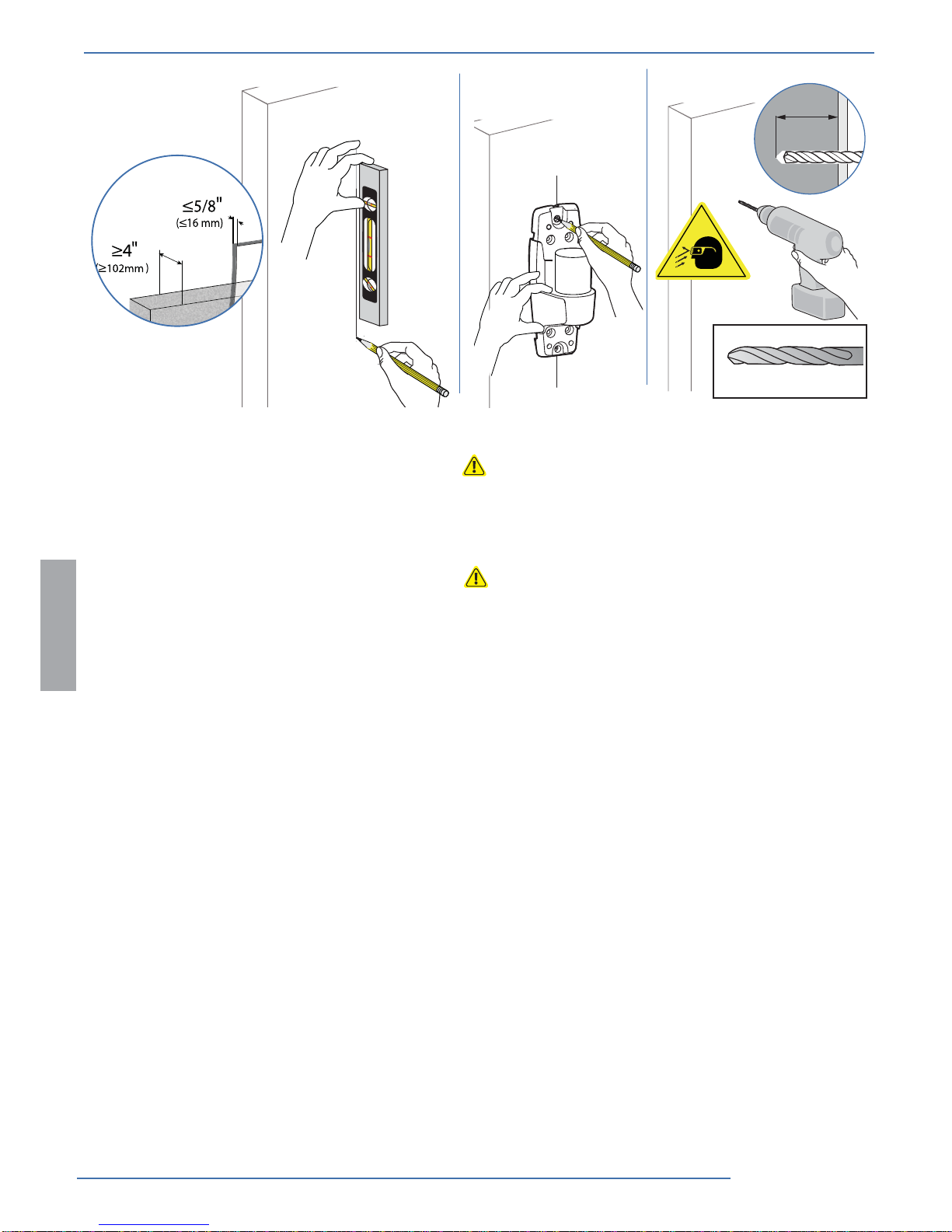
CAUTION: Make sure the wall mount bracket is level,
ush and snug to the wall surface. DO NOT OVERTIGHT-
EN THE BOLTS.
WARNING: Ensure that the wall structure is capable
of supporting four times the total weight of mounted
equipment. Mounting to wall surfaces that do not meet
this criteria may result in an unstable, unsafe condition
which could lead to personal injury and/or property
damage. Consult a construction professional if you
have any doubt about what this means in regard to
your particular application.
Concrete
Ergotron product
Wood