Erica Synths SONIC POTIONS LXR EURORACK User manual

EURORACK OWNERS MANUAL
© Julian Schmidt

TABLE OF CONTENTS
1. MENU NAVIGATION
2 MEMORY MANAGEMENT
2.1. SD Card
2.2. Kits
3 VOICES
3.1. Snare voice (voice 4)
3.2. Cymbal/Clap (voice 5)
3.3. Hihat voice (6)
3.4. Voice parameter menu sections
Oscillator Page (OSC)
Amplitude Envelope Page (AEG)
Modulation Page (MOD)
Frequency Modulation Page (FM)
Transient Generator Page (Click)
Filter Page (FIL)
Mixer Page (Mix)
4 OPERATION MODES
4.1. EDIT mode
4.2. Performance Mode
Basic performance menu
Morph
4.3. Modulation Menu
Mod Matrix)
LFO
4.4. FX Mode
Menu location
Drive
Ringmodulator
Compressor
Delay
4.5. Loading and saving
Display description
Menu navigation
4.6. Global settings menu
Menu location
Menu options
Screensaver
5 SYNTH MODULES
5.1. Oscillator
5.2. Filter
Frequency
Resonance
Drive
Filter types
5.3. Envelopes
Attack/Decay times
Slope
Repeat
5.4. Transient generator
Snappy mode
Offset mode
Sample mode
Parameters
5.5. Sample Rate Reduction
5.6. Distortion
5.7. Accent modulation
5.8. Output Routing
6 FIRMWARE UPDATE
6.1. Update procedure
6.2. Bootloader error messages
7 INTRODUCTION TO DRUM SYNTHESIS
7.1. Kicks
7.2. Snare
7.3. Clap
7.4. Hihat
7.5. Cymbal ride
7.6. Bells
Realistic bells
808 style cowbell
7.7. More info about drum sound design
8 TECHNICAL INFORMATION
8.1. Factory kits are designed by Leoš Hort aka hrtl
8.2. Electrical Specification
8.3. Hardware
8.4. Physical Specification
9 REFERENCES
4
4
4
4
4
5
5
5
5
5
6
7
7
8
8
8
8
8
9
9
9
9
9
10
10
11
11
11
11
12
13
13
13
14
14
14
14
14
14
14
15
15
15
15
17
17
17
18
18
18
18
18
18
19
19
20
20
20
20
20
21
21
21
22
22
23
23
23
23
24
24
24
24
24
24
25

AEG
DRUM2
OSC
DRUM1
MOD
DRUM3
FM
SNARE
CLICK
CLP/CYM
FILTER
CL HH
DRUM1
ACC1
DRUM2
ACC2
DRUM3
ACC3
SNARE
ACC4
CLP/CYM
ACC5
CL HH
ACC6
OP HH
CV1
OUT1
CV2
OUT2
CV3
OUT3
CV4
OUT4
CV5
EDIT PERFORM
MOD FX
DATA
DRUM MIX
OP HH
SHIFT SAVE/LOAD
CONFIG
ERICA SYNTHS SONIC POTIONS
1
4
3
5
7 6
2
THANK YOU FOR PURCHASING THE ERICA SYNTHS X SONIC
POTIONS LXR EURORACK MODULE!
The LXR is a full fledged digital drum generator.
Its sound engine provides 6 different instruments, each with
over 30 parameters to tweak. It can produce a wide variety of
sounds, ranging from classic analogue emulations to crunchy
digital mayhem.
IO JACKS In the first row, we have 7 trigger in jacks (5V) to
trigger the voices and 4 assignable audio outs. The second
row has 6 accent inputs (5V) and 5 freely assignable CV
(-5V to 5V) inputs.
MENU BUTTONS Select the operating mode of the module.
DISPLAY The display is used to show parameter values
from the selected menu page.
ENCODER Navigate through the menu.
ENDLESS POTENTIOMETERS The 4 pots are used to edit
the values shown in the display above.
SELECT BUTTONS Switch voices and select sound
parameter sections.
DRUM BUTTON Used to switch the active voice together
with the select buttons.
1
2
3
7
4
5
6
OVERVIEW

The upper row of the display will show the short name of the
parameter. The bottom row shows the value of the parameter. You can
change the value using one of the 4 knobs below the display.
> The encoder selects a menu parameter. Capital letters highlight the
selected parameter. In our example picture above, the 'RES' parameter
is selected.
> If there are more than 4 entries in the current menu, the next page
will be shown if you scroll over the screen boundary. A '>', '*' or '<' sign in
the right upper corner indicates if there is more than 1 page available
and which page is active. The pages of a menu can be toggled by
pressing the MENU button again.
If you push the encoder the detail page is shown
On the detail page you can see the full name of the parameter and
change its value using the encoder. This is good for fine adjustments,
where the knob control is too coarse. By pushing the encoder again, you
return to the normal menu mode.
Filter
Resonance 120
The LXR offers 6 voices. They are optimized for different kinds of drum sounds. The type of
a voice can not be changed. There are 3 drum voices, a subtractive clap/snare voice, a FM
percussion voice and a hi-hat voice. In this chapter a diagram of the synthesis structure is
shown for each voice type, then the parameters are explained. Let's take a closer look at
the voice types.
VOICES
3
AMP VOL EG
OSCILLATOR
MIX MODE
FM MODE
PITCH EG FILTER AMP
TRANSIENT
GENERATOR
DISTORTION SAMPLE
REDUCER
OSCILLATOR
LXR EURORACK MODULE OWNERS MANUAL 4
MENU NAVIGATION
1MEMORY MANAGEMENT
2
2.1. SD CARD
The memory card is used as non volatile storage. Without a memory card you are not able
to save your work!
2.2. KITS
A kit contains the instrument data for the 6 Voices. All synthesis parameters are stored
here. Kits are stored as .SND binary files inside the Project00 folder on the SD card.
frq
32
RES
120
typ
LP
drv >
0

3.4. VOICE PARAMETER MENU SECTIONS
The synthesis parameters of each voice can be altered in voice EDIT mode. The
synthesis engine is grouped into 7 different sections that can be selected with the
DRUM + SELECT buttons. In this section each of those 7 menu pages and their
parameters are described.
OSCILLATOR PAGE (OSC)
Provides access to the main oscillator parameters. Frequency and waveform of the
main oscillator can be set here.
OSCILLATOR OSCILLATOR
OSCILLATOR
VOL EG
FILTER AMP DISTORTION SAMPLERATE
REDUCER
TRANSIENT
GENERATOR
OSCILLATOR OSCILLATOR
OSCILLATOR
VOL EG
FILTER AMP DISTORTION SAMPLERATE
REDUCER
TRANSIENT
GENERATOR
PITCH EG
VOL EG
OSCILLATOR AMP DISTORTION SAMPLERATE
REDUCER
TRANSIENT
GENERATOR
FILTERNOISE
3.1. SNARE VOICE (VOICE 4)
This voice is good for snare-drum and clap sounds. A noise source and a
pitched oscillator can be mixed. Only the noise source is routed trough the filter.
There is no FM capability on this voice.
3.3 HIHAT VOICE (6)
The hihat voice is nearly identical to the Cymbal voice, but it offers 2 different decay
times for the amplitude envelope. The voice is shared between voices 6 and 7, each
using one of the 2 available decay times. This allows to play open and closed hihats.
The closed hat (voice 6) will choke the open hat (voice 7).
3.2. CYMBAL/CLAP (VOICE 5)
This voice uses a 3 operator FM to generate the sound. The main oscillator is
modulated by 2 modulation oscillators. It's great for metallic and noisy sounds!
LXR EURORACK MODULE OWNERS MANUAL 5

AMPLITUDE ENVELOPE PAGE (AEG)
Each voice has an amplitude envelope. The common parameters are attack and
decay time as well as the slope of the curve.
Drum 1-3, Clap, Hihat
Displayed name Name Description
Coarse tuning of the main oscillator
in semitones.
coa Coarse tune
Fine tuning of the main oscillator
+/- 50 cent.
fin Fine tune
The waveform of the main oscillator.
wav Waveform
If the PWM waveform is selected,
its duty cycle can be adjusted here.
pwm Pulsewidth
Drum 1-3
Displayed name Name Description
Rise time of the envelope.
att Amplitude envelope attack
Fall time of the envelope.
dec Amplitude envelope decay
Variable slope from exp to linear
to logarithmic.
slp Amplitude envelope slope
Hihat
Displayed name Name Description
Rise time of the envelope.
att Amplitude envelope attack
Envelope fall time for the hihats.
D1 / D2 Closed / Open hihat
decay time
Variable slope from exp to lin to log.
slp Amplitude envelope slope
Snare/Cymbal
Displayed name Name Description
Rise time of the envelope.
att Amplitude envelope attack
Fall time of the envelope.
dec Amplitude envelope decay
Number of retriggers.
rpt Repeat count
Variable slope from exp to linear
to logarithmic.
slp Amplitude envelope slope
Snare
Displayed name Name Description
Coarse tuning of the main oscillator
in semitones.
coa Coarse tune
Fine tuning of the main oscillator
+/- 50 cent.
fin Fine tune
Coarse tuning of the noise
oscillator.
noi Noise frequency
Mix ratio between oscillator and
noise source.
mix Oscillator mix
The waveform of the main
oscillator.
wav Waveform
If the PWM waveform is selected,
its duty cycle can be adjusted here.
pwm Pulsewidth
LXR EURORACK MODULE OWNERS MANUAL 6

MODULATION PAGE (MOD)
If the selected voice offers a second envelope, it's parameters can be found here.
The modulation page also contains the accent velocity modulation. Here you can
turn the accent to volume modulation on and off.
Drum 1-3, Snare
Displayed name Name Description
Fall time of the envelope.
dec Modulation envelope decay
Variable slope from exp to
linear to logarithmic.
slp Modulation envelope slope
Can be either On or Off.
If activated the accent signal
controls the voice volume.
vol Accent to volume modulation
> Controls how strongly the
envelope modulates its target.
> The envelope is hardwired to
the pitch. This parameter
controls the pitch modulation
intensity.
> In FM mode the EG is
additionally hardwired to the
FM amount.
mod Modulation envelope amount
Clap, Hihat
Displayed name Name Description
Can be either On or Off.
If activated the accent signal
controls the voice volume.
vol Velocity to volume modulation
Description
Frequency of the first modulation oscillator.
Frequency of the second modulation oscillator.
Gain of the first modulation oscillator.
Gain of the second modulation oscillator.
Waveform of the first modulation oscillator.
Waveform of the second modulation oscillator.
Clap, Hihat
Displayed name Name
f1 Frequency 1
f2 Frequency 2
g1 Gain 1
g2 Gain 2
wav Waveform 1
wav Waveform 2
SNARE
Voice 4 offers no FM capabilities at the moment, so the Page is empty.
FREQUENCY MODULATION PAGE (FM)
The FM page hosts the frequency, waveform and modulation amount settings for
the FM oscillators.
Displayed name Name Description
FM mode: modulation amount
Mix mode: Mix ratio of the 2 OSCs.
amt Modulation amount
[mix ratio]
Coarse tuning of the FM oscillator
in semitones.
frq Frequency of the FM OSC
The waveform of the FM oscillator.
wav Waveform of the FM OSC
FM mode: the main OSC is
modulated by the FM OSC
Mix mode: The main OSC and FM
OSC are mixed.
mod Oscillator mode
LXR EURORACK MODULE OWNERS MANUAL 7

TRANSIENT GENERATOR PAGE (CLICK)
The transient generator parameters are the waveform, volume and frequency of
an additional short attack transient that can be mixed to the voice output.
wav
vol
frq
Transient wave shape
Transient volume
Transient frequency
Selects the transient sample to play.
Volume of the transient sample.
Frequency of the transient sample.
Displayed name Name Description
frq
res
typ
drv
Filter frequency
Filter resonance
Filter type
Filter drive
Changes the cutoff frequency of the filter.
Adjusts the filter resonance.
Selects the filter characteristic.
Increases the input gain of the filter.
FILTER PAGE (FIL)
All parameters of the filter are on this page. The available parameters are
frequency, resonance, type and drive.
Displayed name Name Description
Voice panning. Only active if output
is set to a stereo channel.
pan Voice panning
Sample rate decimation.
sr Sample rate
Soft clipping amount.
drv Drive
Selects the hardware audio out for this
voice. The voice can either be routed to
one of the 2 stereo channels or use the
4 outputs as individual mono channels or
the FX bus.
out Output
MIXER PAGE (MIX)
The mixer page provides access to volume, panning, routing, voice FX and
sequencer track length.
Displayed name Name Description
Adjusts the volume of the voice.
vol Voice volume
MENU
4
LXR EURORACK MODULE OWNERS MANUAL 8
There are different menus for different tasks. Voice editing, performance or
modulation and FX routing. The main modes are accessible with the 6 MENU buttons.
4.1. EDIT MODE
The voice EDIT mode is used to modify the sound parameters for each voice.
> The parameters of the voice are divided into several pages which can be selected
using the 7 SELECT buttons (6).
> While the DRUM button (2) is held, the 7 SELECT buttons (6) select the active voice,
which is indicated by a lit LED.
> Each voice type has its own set of parameters, but the overall page structure is the
same for all voices.
> Parameters in the display can be edited using the 4 knobs below.
4.3. MODULATION MENU
MOD MATRIX
Each voice has a 3 slot mod matrix where the CVs, accents and LFOs can be routed
to any parameter of the synth engine. The mod matrix can be accessed with the
MOD button.
The voice can be selected by holding the DRUM button and pushing one of the
SELECT buttons while the mod matrix menu is active.
Parameter editing
As an example lets
take a look at the
filter page:
Frq
32
res
120
typ
LP
drv
0
To change the frequency of the filter of voice 3
> Press 'DRUM + SELECT Button 3' to select the voice.
> Press 'SELECT button 6' to show the filter page.
> Use the first knob to adjust the 'frq' parameter.
4.2. PERFORMANCE MODE
This mode is designed to jam live. You can manually trigger the voices using the
SELECT buttons and access the morph and global sample rate FX. There is no
voice editing possible in this mode.
Displayed name Name Description
Ratio between the original sound and
the morph target.
mrp Morph amount
Select the kit number of the morph target.
mtg Morph target
A global sample rate reduction effect.
sr Global samplerate
Displayed name Name Description
There are 17 modulation sources to
choose from:
> 5 CVs from the input jacks
> 6 LFOs
> 6 Accent signals
src Modulation Source
Modulation strength 0% to 100%
amt Modulation Amount
Target sound parameter list from
the current voice
dst Modulation destination
BASIC PERFORMANCE MENU
In performance mode the display shows a set of 3 parameters.
MORPH
The morph feature allows you to morph from one preset sound to another. You can
use any kit as a morph target. The Morph amount value controls the ratio between
the original and the target sound. As the morph parameter is increased, the current
sound is gradually transformed into the selected morph target sound.
Did you know?
If morphing arbitrary presets is too drastic for you, try modifying your
favorite pattern just a little bit and save it to a new location. Now you
can control all tweaked parameters at once!
LXR EURORACK MODULE OWNERS MANUAL 9

The modulation is bipolar around the current value of the parameter. So for a full
range modulation the target parameters value is best set to 50%.
The mod matrix has a special mod target called “v/o”. Using this target, the
incoming Cvs are scaled to allow tonal play of the voices using a 1V/Oct CV
source. Amount has to be set to 100% for exact tracking. In 1V/Oct mode negative
CVs are ignored. This gives you a 5 octave range.
LFO
There are 6 low frequency oscillator. They are basically the same as the audio
oscillators, but run at a lower maximum rate.
The LFO menu is accessed by pressing SHIFT + MOD.
The 6 LFOs can be selected by holding the DRUM button and pushing one of the
SELECT buttons while the LFO menu is active.
Unlike the audio oscillators you can not hear the LFOs directly. They are used to
alter other parameter values over time. For example if you want the filter of a
voice to slowly open and close again, you can use a sine lfo to modulate the filter
cutoff.
4.4. FX MODE
The LXR provides a digital FX processor. Only 1 effect can be used at a time. Currently
there are 4 FX available: Drive, Ringmodulator, Compressor and Delay.
You can use the FX processor, by setting the output routing on the mixer page to
“FX”. So the voice will be routed to the FX bus before going to the output. So you can
select which of the voices will be processed by the FX processor.
Displayed name Name Description
Manual LFO rate control. Only available
when sync is turned off!
frq LFO frequency
When the LFO is retriggered, it is reset
to the selected phase offset.
off Phase offset
Select the LFO waveform.
> Sine (sin)
> Triangle (tri)
> Saw up (sup)
> Saw down (sdn)
> Square (sqr)
> Random (rnd)
> Exponential saw up (xup)
> Exponential saw down (xdn)
wav LFO waveform
Allows the LFO to be retriggered from
different sequencer tracks. Select the
voice that should retrigger the LFO (v1-v6)
and it will reset its phase whenever a
note is played on the selected track.
rtg LFO retrigger
Did you know?
You can use the LFO as an additional envelope using the retrigger
feature. If set to the same voice as the modulation destination, the LFO
will restart on every played note. You just have to set the LFO frequency
so that one cycle of the LFO is slightly longer than the amplitude
envelope, so it won't start a new cycle while the note is still playing. Great
for filter decay envelopes on juice synth bass souds!
LXR EURORACK MODULE OWNERS MANUAL 10

MENU LOCATION
The FX menu is accessed by pushing SHIFT + FX
DRIVE
The drive FX is a collection of different distortion algorithms. It offers 3 different
types of saturation. In contrast to the drive parameter of the single voice filter
and mixer pages, this FX processes all signals in a single distortion unit. This leads
to interesting inter modulation between the input signals.
Drive Types
The 4th parameter “type” selects the drive algorithm to use.
> Tub – Adds tube Saturation
> Fld – A wavefolder distortion
> Clp – A rodent inspired hardclip pedal emulation
Displayed name Name Description
Drive
typ FX Type
Selects the Audio output the FX signal is
mixed to.
out Output routing
Mixing ratio between the original and the
FX signal.
d/w Dry / Wet ratio
Select the drive type (Tube, Fold, Clip)
typ Drive Type
Parameters
Input gain of the distortion unit.
drv Drive strength
Tone Control Filter.
ton Tone
Tube
Bias
Fold
Offset
Clip
Feedback
col Colour
Output volume of the distortion.
vol Volume
The feedback parameter of the Clip processor will generate a tone
when no input is present. This is the normal behavior, as the effect
is quite similar to the feedback sound a microphone in front of a
speaker produces. While a drum pattern is playing, it gives nice
intermodulation, but without input a clean tone is produced. Just
pull down the master volume if you stop the sequencer when you
are using full feedback or use an external VCA.
COMPRESSOR
A compressor is a dynamic processor that is able to reduce the volume of loud
sounds and boost the volume of quiet sounds, thus reducing the dynamic range of
the signal.
RINGMODULATOR
The ringmodulator multiplies the input signal with a second oscillator signal.
Ever wanted to hear a Dalek beatboxing? Then the ringmod is your friend!
Displayed name Name Description
Ring.
typ FX Type
Selects the Audio output the FX signal
is mixed to.
out Output routing
Mixing ratio between the original and
the FX signal.
d/w Dry / Wet ratio
Modulation Waveform.
wav Waveform
Frequency of the modulation waveform.
frq Frequency
Parameters
LXR EURORACK MODULE OWNERS MANUAL 11

Displayed name Name Description
Compressor.
typ FX Type
Selects the Audio output the FX signal
is mixed to.
out Output routing
Mixing ratio between the original and
the FX signal.
d/w Dry / Wet ratio
Parameters
1:1 up to 8:1 in dB. Strength of the
compression. For example a ratio of
2:1 will attenuate the volume of a
signal 2dB above the treshold down
to 1dB above the treshold.
rat Compression ratio
Time it takes for the compressor to
kick in. 0.3 to 100ms range.
atk Attack
Time it takes to return to normal gain,
after the input falls below the treshold.
25 to 200ms range.
dec Decay
The treshold sets the level at which the
compression effect sets in. -96 to 0dB.
tre Treshold
Compression lowers the volume. Use
the output gain to make up for the
difference.
gai Makeup Gain
Displayed name Name Description
Delay.
typ FX Type
Selects the Audio output the FX signal is
mixed to.
out Output routing
Mixing ratio between the original and the
FX signal.
d/w Dry / Wet ratio
The 4th parameter “type” selects the
delay algorithm to use.
> Del – Mono delay
> Pp – Stereo ping pong delay.
The feedback alternates between the left
and right channel. Pan must be set to a
non zero value to work!
typ Delay type
Adjust the delay time in the range
specified by the range parameter.
tim Delay time
Sets the range for the delay time dial.
The low range is 1ms to 20ms
The high range is 20ms to 0.7sec.
rng Time range
Frequency of the lowpass filter in the
feedback path.
ton Tone
Controls the number of repeats.
fbk Feedback
Parameters
LXR EURORACK MODULE OWNERS MANUAL 12
DELAY
Straight forward delay FX. Not much to say here. It’s a classic!
Try using the range control for very short delay times and LFO modulation to get
some flange action going!

4.5. LOADING AND SAVING
When the LXR is turned on, the last used kit is automatically loaded from the SD
card to the machines memory.
After this initial load, all changes made are temporary. If another kit is selected,
all changes to the current kit are lost.
To make these changes permanent, you have to save the kit to commit them to
the SD card.
The SAVE/LOAD button will bring up the kit load menu. SHIFT + LOAD/SAVE will
bring up the save menu.
> The first row of the display gives information about the active mode
(load or save)
> The second row chooses the active preset no. and displays the name of the
selected preset.
> You confirm the selection by pushing the encoder button to load/save a kit.
MENU NAVIGATION
> Use the encoder to navigate trough the menu.
> Push the encoder to confirm your selection.
DISPLAY DESCRIPTION
Load: Kit
[1] Name
LXR EURORACK MODULE OWNERS MANUAL 13
Quick naming scheme
To speed up the name entry on the save page you can also use the knobs below the
display. If the cursor is in the name area the knobs have the following functions:
> The first knob selects the cursor position.
> The second knob switches between upper and lower case letters.
> The third knob scrolls through the available default ASCII characters.
Kit Loading
> Press LOAD/SAVE
> Select a new kit with the encoder.
> To load the selected kit push the encoder.
> The kit sound will play immediately
> unsaved changes to the previous kit are lost
Kit Saving
> Press SHIFT + LOAD/SAVE
> Select the preset number you want to save your kit to.
> Push the encoder
> You will be asked : ”Edit Name? [y/N]”
> if you don’t want to change the name, push the encoder and you kit is saved.
> if you want to change the name, use the encoder to navigate to [Y/n] and push it.
> Navigate to the letters of the name.
> You can change the letters if you push the encoder and turn it or refer to the quick
naming scheme
> If you are happy with the name, navigate the cursor to the 'ok' button and push the
encoder down to save the kit.

4.6. GLOBAL SETTINGS MENU
The settings menu contains the global configuration of the synth. Settings will be
saved as soon as you exit the menu.
MENU LOCATION
> Press the SHIFT + LOAD/SAVE buttons
> The SHIFT + LOAD/SAVE button starts to flash to indicate that the global
settings menu is active.
MENU OPTIONS
Displayed name Name Description
Turn the screensaver on or off
ssv Screensaver
Save the CV routing globally or on a
per kit basis
cv Global CV Save
In this chapter we will have a closer look at the synth modules used in the different
voices.
5.1. OSCILLATOR
The oscillators provide 6 different waveforms:
> Sine
> Triangle
>Saw
> Rectangle
> Noise
> PWM
The waveforms are classic analogue waveforms realized using bandlimited wavetable
oscillators.
5.2. FILTER
The filter is a 2 pole (12dB) state variable filter (SVF). It's used to shape the harmonic
content of the sound. For example a hihat sound consists of high frequencies and no
low frequencies, so you want to use a highpass filter. A clap has lots of mid sounds,
here a bandpass filter is useful.
There are 3 parameters that control the filter response. Frequency, resonance and
drive.
SYNTH MODULES
5FREQUENCY
The frequency determines the operating point of the filter in the spectrum.
For example a low pass filter will cut off all frequencies above its set cutoff
frequency (all frequencies below it pass the filter unaltered – hence the name).
RESONANCE
The resonance controls the feedback path of the filter. With higher resonance
settings the frequencies around the operating point (i.e. the set frequency) will
be amplified more and more.
It becomes clear if we look at the filter amplitude response plots in the next
section.
DRIVE
Controls how 'hot' the filter is driven. More drive yields in more distortion. In the
normal operating range, when drive is set to 0, the filter is quite clean and nearly
linear. With higher input levels/drive settings, a soft clipper as well as the slew
rate limit of the integrators comes into effect. Low settings will only affect the
resonance peaks, higher settings will distort the whole signal. Since the soft
clipper is scaling down excessive peaks in the signal, the audible resonance is
reduced with higher drive settings.
FILTER TYPES
There are several different filter types available, each with it's own characteris-
tics. Let's have a closer look at each one of them. The filters are plotted with 3
different resonance settings. No resonance, medium and high. The cut off
frequency is the same in every plot and marked by the vertical dashed line.
The x axis shows the frequency from 0Hz to 22kHz, the y axis shows the gain for
the specific frequency - Both on a logarithmic scale.
LXR EURORACK MODULE OWNERS MANUAL 14
SCREENSAVER
The display provided with the kit is an OLED display. To expand the lifetime of the
OLED display and to avoid burn in, the firmware provides a screensaver for the
display. After no control is touched for some minutes, the display will show the
screensaver. As soon as any control is touched, the display will show the menu
again. The screensaver can be deactivated in the settings menu.

In this chapter we will have a closer look at the synth modules used in the different
voices.
5.1. OSCILLATOR
The oscillators provide 6 different waveforms:
> Sine
> Triangle
>Saw
> Rectangle
> Noise
> PWM
The waveforms are classic analogue waveforms realized using bandlimited wavetable
oscillators.
5.2. FILTER
The filter is a 2 pole (12dB) state variable filter (SVF). It's used to shape the harmonic
content of the sound. For example a hihat sound consists of high frequencies and no
low frequencies, so you want to use a highpass filter. A clap has lots of mid sounds,
here a bandpass filter is useful.
There are 3 parameters that control the filter response. Frequency, resonance and
drive.
FREQUENCY
The frequency determines the operating point of the filter in the spectrum.
For example a low pass filter will cut off all frequencies above its set cutoff
frequency (all frequencies below it pass the filter unaltered – hence the name).
RESONANCE
The resonance controls the feedback path of the filter. With higher resonance
settings the frequencies around the operating point (i.e. the set frequency) will
be amplified more and more.
It becomes clear if we look at the filter amplitude response plots in the next
section.
DRIVE
Controls how 'hot' the filter is driven. More drive yields in more distortion. In the
normal operating range, when drive is set to 0, the filter is quite clean and nearly
linear. With higher input levels/drive settings, a soft clipper as well as the slew
rate limit of the integrators comes into effect. Low settings will only affect the
resonance peaks, higher settings will distort the whole signal. Since the soft
clipper is scaling down excessive peaks in the signal, the audible resonance is
reduced with higher drive settings.
FILTER TYPES
There are several different filter types available, each with it's own characteris-
tics. Let's have a closer look at each one of them. The filters are plotted with 3
different resonance settings. No resonance, medium and high. The cut off
frequency is the same in every plot and marked by the vertical dashed line.
The x axis shows the frequency from 0Hz to 22kHz, the y axis shows the gain for
the specific frequency - Both on a logarithmic scale.
Highpass
The highpass filter removes low frequencies from the signal. All frequencies below
the cutoff frequency are reduced gradually.
Lowpass
The lowpass filter removes high frequencies from the signal. All frequencies above
the cut off frequency are reduced gradually.
18 dB
12 dB
6 dB
0 dB
-6 dB
-12 dB
-18 dB
18 dB
12 dB
6 dB
0 dB
-6 dB
-12 dB
-18 dB
LXR EURORACK MODULE OWNERS MANUAL 15

Notch
The notch filter removes frequencies around the set filter frequency. Again, the
resonance controls the width of the stopband.
Peak
The peak filter amplifies frequencies around the filter frequency, but lets the
other frequencies pass nearly unaltered. The resonance controls the amount of
amplification.
18 dB
12 dB
6 dB
0 dB
-6 dB
-12 dB
-18 dB
18 dB
12 dB
6 dB
0 dB
-6 dB
-12 dB
-18 dB
Bandpass
The bandpass filter removes frequencies above and below the set cutoff frequency.
Unit gain bandpass
The unit gain bandpass is a scaled version of the normal bandpass filter. The
gain is always adjusted to have its maximum around 0dB gain. Unlike the normal
bandpass, where the resonance controls the amplitude of the peak gain, it
controls the width of the passband.
18 dB
12 dB
6 dB
0 dB
-6 dB
-12 dB
-18 dB
18 dB
12 dB
6 dB
0 dB
-6 dB
-12 dB
-18 dB
LXR EURORACK MODULE OWNERS MANUAL 16

LP2 Type
This type is a special case. It replaces the SVF model with a simpler
implementation of the SVF topology with much more digital resonance. Use it for
those screaming acid sounds!!
5.3. ENVELOPES
Envelopes are used to generate a varying control signal that can control other
synthesis parameters. Whenever a voice is triggered, the envelope is restarted.
The signal rises with the speed selected by the attack setting until it reaches the
maximum amplitude. Then it will fall back down to zero, with the speed set by the
decay parameter.
ATTACK/DECAY TIMES
These 2 parameters control the duration of the attack and decay stage of the
envelope. A higher value equals longer time. If the attack time is set to zero, the
envelope will directly start in the decay stage.
A linear envelope curve
Time
Amplitude
Attack Decay
Time
Amplitude
Attack Decay
Time
Amplitude
Attack Decay
SLOPE
The slope parameter controls the shape of the generated curve. A setting of 63 will
give you a linear envelope as seen above. Lower settings will result in an exponential
curve, higher values result in a logarithmic curve.
Curve with a low slope setting. Exponential decay stage.
Curve with a high slope setting. Logarithmic decay stage.
LXR EURORACK MODULE OWNERS MANUAL 17
SNAPPY MODE
The snappy mode is the first entry in the selection list, shown in the menu as 'Snp'
To make the attack of the sound more 'snappy' an additional pitch envelope is used.
> The volume parameter controls the modulation depth.
> The frequency parameter controls the decay time.
The envelope is quite fast and modulates the pitch of the oscillators resulting in a
nice, controllable snap or click sound.
OFFSET MODE
The second entry is the offset mode with the menu name 'Off'.
In this mode the start phase of the oscillators can be adjusted with the volume
parameter. The frequency parameter has no effect.
If the volume is set to zero, the oscillators will be reset to a zero crossing of the
waveform on each trigger. If the volume parameter is set to its maximum value, the
waveform will start on the position with the highest amplitude, generating a loud pop.
This results in the volume parameter controlling the intensity of the initial pop.
SAMPLE MODE
A short transient sample is mixed to the sound. They are short (~50ms) 8-bit ROM
samples that are played as a one shot whenever the sound is triggered. Different
samples can be selected.
PARAMETERS
The parameters of the transient generator include the PCM waveform to use, the
playback frequency and the volume. The ROM samples can't be changed by the user
on the fly. They are hard coded into the firmware.
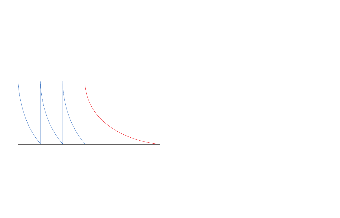
REPEAT
A special feature of the envelope to simulate claps and other sounds with a
fuzzy/rattling attack.
If the repeat count is set to a value greater than zero, the envelope is in repeat
mode.
The slow onset of the attack stage is replaced by the repeat stage in which the
envelope is retriggered rapidly. The attack parameter controls the duration of the
complete repeat phase.
5.4. TRANSIENT GENERATOR
The transient generator is used to shape the beginning of a sound. Since the
perception of sounds is heavily influenced by their first few milliseconds, this
feature is useful to spice up or vary the sound character of an instrument.
There are different modes the transient generator uses to shape the attack.
Repeat Phase
Repeat Count = 3, Decay controled by attack settings
Decay Phase
LXR EURORACK MODULE OWNERS MANUAL 18

A list of the included samples:
Displayed name Name Description
Snp Snappy Mode
Off Offset Mode
Displayed name Name Description
Clk Click
Ck2 Click 2
Tik Tick Some kind of tick sound1
Kik Acoustic kick An acoustic kick drum2
Rim Rim shot A rim shot sound3
Drp Drip A dripping sound made by a human being4
Hat Tick Some kind of tick sound5
Tik Hat Sampled off of Zildjian A-Custom Hi-Hats6
Clp Clap 808 clap7
Ki2 Kick 2 A kick sample
Sna Snare A snare sample
Tom Tom A tom sample (sort of)
Sp2 Snap A finger snap
Transient Samples
5.5. SAMPLE RATE REDUCTION
The sample rate reducer can gradually reduce the sample rate from 44kHz to zero.
Reducing the sample rate will give more of a lo-fi sound. The more it is reduced, the
more odd harmonics will be added to the sound as overtones are folded down at the
Nyquist frequency until the sound is totally destroyed.
5.6. DISTORTION
The distortion unit on the mixer page is a variable waveshaper. It can be set from no
distortion, over soft saturation up to hard clipping.
max
mid
low
1.5
1
0.5
0
-0.5
-0.5 0 0.5 1
-1
-1
LXR EURORACK MODULE OWNERS MANUAL 19

5.7. ACCENT MODULATION
The accent can be used as a modulation source and is an important tool to bring
some life to your static patches. The accent can modulate 2 destinations
simultaneously.
> The voice volume.
> Any parameter of the voice.
By default the velocity is modulating the voice volume. This hard wired
connection can be turned off in the modulation menu with the 'Vol' on/off
parameter
5.8. OUTPUT ROUTING
Each voice can be freely routed to the 4 different output jacks. They act either as
4 individual mono outs (pan parameter has no effect) or as 2 pairs of stereo
outputs. There is an additional FX bus available as routing target as well. Have a
look at the FX section of the manual for more info.
The software for the LXR can be updated using the memory card.
6.1. UPDATE PROCEDURE
> Copy the latest LXRE_V2_xxx.img to the root of the SD card.
> Delete any old firmware .img files from the SD card.
> Push and hold the encoder button while turning on the device.
> “LXR Bootloader” will pop up in the display
> The LXR will check if the firmware image is valid and has the proper checksum
> If the check is passed, the update will be installed.
> Do not turn off the power during installation!
> Once done, the LXR will prompt you to reboot and the new firmware will be running.
6.2. BOOTLOADER ERROR MESSAGES
LXR*.img Not Valid!
File doesn’t seem to be a valid firmware file. File header not matching
LXR*.img Wrong size!
Filesize differs from the size specified in the header. Probably an incomplete
download.
Wrong Checksum
File corrupted. File content does not match the checksum. Probably a download
error.
FIRMWARE UPDATE
6
LXR EURORACK MODULE OWNERS MANUAL 20
Table of contents
Other Erica Synths Recording Equipment manuals

Erica Synths
Erica Synths POLIVOKS-INSPIRED EG User manual

Erica Synths
Erica Synths EDU DIY Wavefolder User manual

Erica Synths
Erica Synths SWAMP User manual

Erica Synths
Erica Synths COMPRESSOR User manual

Erica Synths
Erica Synths Black Series User manual

Erica Synths
Erica Synths Drum Sequencer User manual

Erica Synths
Erica Synths POLIVOKS-INSPIRED VCA User manual

Erica Synths
Erica Synths BBD DELAY/FLANGER User manual

Erica Synths
Erica Synths MIDI-CV User manual

Erica Synths
Erica Synths fusionbox User manual


