manuals.online logo
Brands
  1. Home
  2. •
  3. Brands
  4. •
  5. Erica Synths
  6. •
  7. Recording Equipment
  8. •
  9. Erica Synths BBD DELAY/FLANGER User manual

Erica Synths BBD DELAY/FLANGER User manual

GUIDE TO ASSEMBLY OF ERICA SYNTHS DIY BBD DELAY/FLANGER
If you are reading this, most probably, you
are about to build Erica Synths DIY BBD
DELAY/FLANGER module. The module is 14HP
wide, 45mm deep, skiff friendly, has solid
mechanical construction and doesn’t require
wiring.
Erica Synths DIY BBD Delay /FLANGER is one
of few BBD (bucket brigade delay) chips based DIY
modules. The module is designed to provide
variety of effects from flanger to delays with
adjustable flavours and plenty of modulation
possibilities. It has built in LFO with selectable
shape and dedicated LFO output, delay time CV
input with an attenuator, selectable feedback
overdrive and feedback Send-Return connectors,
so you can apply external effects on feedback
signal. Maximums feedback settings put the
module in self oscillation, so it can be used as an
experimental sound source, as well.
The DIY kit comes in three versions:
1) Set of 2 PCBs + BBD ICs (V3205 and V3102),
2) Set of 2 PCBs + BBD ICs + mechanical parts
(PCB connectors and spacer)+ panel,
3) Full kit.
FEATURES:
•4092 stage BBD
•Up to 300ms delay time
•Delay time CV input with an attenuator
•Feedback Send-Return circuit for external
effects
•Built in LFO with dedicated output
•Two customizable feedback overdrive flavours
•LP filter on the output with selectable cutoff
•Dedicated Wet output
SPECIFICATIONS:
•Max Delay time 300ms
•Audio output amplitude 10Vptp
•CV amplitude (full span) -5V - +5V
•Panel width 14HP
•Module depth 45mm
•Power consumption 30mA @+12V,
20mA@-12V
1
2
3
4
5
6
7
8
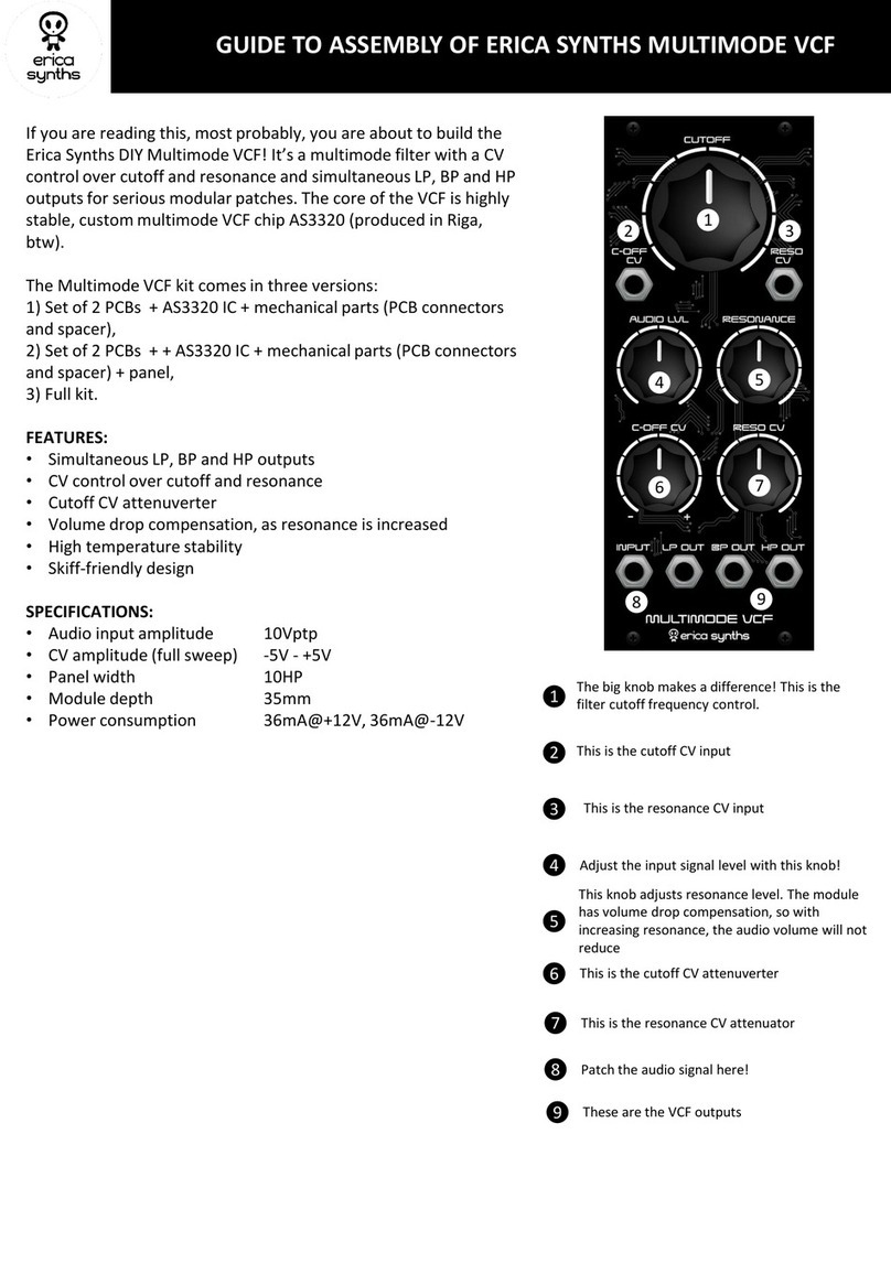
The big knob sets delay time from 0 CCW to 300ms CW.
The COLOUR switch applies the LP filter of two selectable cutoff
frequencies on the output. Mid position means –no filter applied,
top position is “Darker”, bottom position “Dark”. Use the filter with
low frequency audio on the input!
Select one of two feedback signal overdrive flavours
Adjust feedback level! In full CW setting the module will go to self
oscillation
This is the Dry/Wet crossfade control
Adjust the audio input level! DDB Delays are sensitive to the audio
input level, so experiment with settings to get different results!
9This is the delay time CV attenuator. It’s internally patched to built
in LFO, but when you patch a external modulation signal, the
internal connection is replaced by the external one
10 This is the feedback FX Send output, meaning, you can break the
feedback path and send the feedback signal to external modifiers,
multimode filter, for example
11 This is the feedback FX return input. Patch the modified signal back
here!
12 This is the audio signal input. Adjust the signal level for various effect
flavours!
13
14
15
Select the built in LFO shape
Adjust the built in LFO frequency. The LFO is internally routed to the
delay time CV through the MOD LEVEL attenuator. The LED will give
visual feedback on the LFO rate.
This is the wet signal output. Here you have another audio
signal to build some interesting patches
1
3
4
2
5
8
7
9
6
10 11
12 13 14 15
15 15
16
This is the output of the module. We believe, you’ll enjoy
results!
16
This is the LFO output. You can use the built in LFO to modulate
other modules in your rack and have interesting synced effects
This is the delay time CV input
Take precautions with regard to electrostatic discharge (ESD) safety. Handling components should be done
in electrostatically safe environment. Use personal and workplace grounding. Any discharge (even a minor
one) from body to a component may permanently damage it.
Our PCBs have silkscreened both component values and designators, but we highly recommend you to print
out files with component placement before you start assembly of the module. And, please, at least take a
look on this manual!
Some components are marked as NU (not used) –leave those unpopulated! Some components are
market as OPTION (those are for optional modifications) –leave those unpopulated for now.
ASSEMBLY
1There are two PCBs –the Control PCB with potentiometers, switches, jack and the Main PCB with components
around BBDs. Solder horizontally placed resistors, diodes and ferrite beads on both PCBs! Pay attention on
orientation of diodes!
2Solder IC sockets, and then ceramic and film capacitors on both PCBs!
GUIDE TO ASSEMBLY OF ERICA SYNTHS DIY BBD DELAY/FLANGER
3Turn the Control board around and solder electrolytic capacitors, the PSU connector and 1x10 pin female
connectors! Also fix the 11mm spacer on the board. Solder transistors, electrolytic capacitors on the Main board!
Pay attention on the orientation of both! Also solder the trimpots on the main board.
4Solder transistor, resettable fuses, potentiometers, switches and
jacks on the control board! Insert the LED, but do not solder it, yet!
Switches have two nuts –remove one of them and screw other on
until it’s fixed against the switch! Next to the FEEDBACK DRIVE switch
you’ll find solder pads for overdrive diodes. You can use any diodes of
your taste for pairs VD4/VD5 and VD6/VD11 or VD7/VD10 which are
LEDs. The kit contains two red LEDs (if you use LEDs, do not populate
VD6/VD11) and 1N4148 for VD4/VD5. You may experiment here with
different diodes (try germanium diodes for softer overdrive) of LEDs
of various colours –it will result in different overdrive flavour. I used
33k for R71 and 100k for R72 in the overdrive configuration supplied
with a kit.
5Solder 1x10 pin male connectors on
the Main board!
Negative lug of the
electrolytic
capacitor is marked
with a stripe!
GUIDE TO ASSEMBLY OF ERICA SYNTHS DIY BBD DELAY/FLANGER
5Place the panel on the Controls board fix it with couple of
nuts and push the LED through the hole. Solder the LED!
Remove the panel, install ICs on both boards (pay close
attention to the orientation of ICs!) and connect both boards
together as shown on the picture! Now you can connect the
module to the PSU! Set all switches in the middle position, IN
LEVEL full clockwise, Dry/Wet and MOD LEVEL full CCW, other
potentiometers at 12 o’clock! Check if you get some sound
from the module in the DRY setting and then fade the
potentiometer to the WET setting. You should hear the wet
signal, as well.
6Now it’s time for initial calibration! There are
two trimpots on the main board.
R8 is BBD offset adjustment. Connect the WET
OUT to the oscilloscope or mixer with
headphones and feed the sinewave in the audio
INPUT and adjust the trimpot for the least
distortion (you can do it just listening to the
signal on WET output).
R7 stets maximum delay time. Adjust it to your
taste. The longer is the delay, the noisier gets
the signal, so find the compromise.
7Now, let’s take care about feedback overdrive circuit! One
side of the switch in top or bottom position connects set of
overdrive diodes to the feedback circuit; other part, adjusts
feedback gain, meaning, different diodes limit the signal in
unique way, and you need to adjust the gain of the feedback
signal, so that the module goes into self-oscillation at
approximately same setting for all switch positions. R71 sets
gain for VD4/VD5, R72 sets gain for LEDs. Please, note that
using different diodes or LEDs than supplied with a kit may
require selection of R71 and R72
8Now, you can install the front panel and
knobs. Don’t forget to fix the Main board to
the spacer, using a M3 screw.
The module is ready to use! Enjoy!
GUIDE TO ASSEMBLY OF ERICA SYNTHS DIY BBD DELAY/FLANGER

Other Erica Synths Recording Equipment manuals

Erica Synths Multimode VCF User manual

Erica Synths

Erica Synths Multimode VCF User manual

Erica Synths fusionbox User manual

Erica Synths

Erica Synths fusionbox User manual

Erica Synths SWAMP User manual

Erica Synths

Erica Synths SWAMP User manual

Erica Synths MIDI-CV User manual

Erica Synths

Erica Synths MIDI-CV User manual

Erica Synths Black Series User manual

Erica Synths

Erica Synths Black Series User manual

Erica Synths SONIC POTIONS LXR EURORACK User manual

Erica Synths

Erica Synths SONIC POTIONS LXR EURORACK User manual

Erica Synths POLIVOKS-INSPIRED EG User manual

Erica Synths

Erica Synths POLIVOKS-INSPIRED EG User manual

Erica Synths COMPRESSOR User manual

Erica Synths

Erica Synths COMPRESSOR User manual

Erica Synths POLIVOKS-INSPIRED VCA User manual

Erica Synths

Erica Synths POLIVOKS-INSPIRED VCA User manual

Erica Synths EDU DIY Wavefolder User manual

Erica Synths

Erica Synths EDU DIY Wavefolder User manual

Erica Synths Drum Sequencer User manual

Erica Synths

Erica Synths Drum Sequencer User manual

Erica Synths Black DUAL VCF User manual

Erica Synths

Erica Synths Black DUAL VCF User manual

Popular Recording Equipment manuals by other brands

Lode Schiller CS200 Service documentation

Lode

Lode Schiller CS200 Service documentation

Focusrite Saffire Pro 10 I/O Guide manual

Focusrite

Focusrite Saffire Pro 10 I/O Guide manual

Bode 7702 user manual

Bode

Bode 7702 user manual

AirTools Voice Processor 2x quick start guide

AirTools

AirTools Voice Processor 2x quick start guide

Axis JS007WQK installation manual

Axis

Axis JS007WQK installation manual

Emerson IEC 62591 instruction manual

Emerson

Emerson IEC 62591 instruction manual

Strymon COMPADRE quick start guide

Strymon

Strymon COMPADRE quick start guide

AND FG-27CWPJA instruction manual

AND

AND FG-27CWPJA instruction manual

Citizen CT-E351ET manual

Citizen

Citizen CT-E351ET manual

Yamaha MDF3 owner's manual

Yamaha

Yamaha MDF3 owner's manual

Daktronics SPORTS WIRE 4000 INTERFACE Installation & operation manual

Daktronics

Daktronics SPORTS WIRE 4000 INTERFACE Installation & operation manual

Hameg HO79-6 manual

Hameg

Hameg HO79-6 manual

ACS AET63 BioTRUSTKey Reference manual

ACS

ACS AET63 BioTRUSTKey Reference manual

Campbell SC-IRDA instruction manual

Campbell

Campbell SC-IRDA instruction manual

OXI ELECTRONIC INSTRUMENTS One user guide

OXI ELECTRONIC INSTRUMENTS

OXI ELECTRONIC INSTRUMENTS One user guide

METRObility Optical Systems twister T1 Installation & user guide

METRObility Optical Systems

METRObility Optical Systems twister T1 Installation & user guide

Vokkero ELITE WI user guide

Vokkero

Vokkero ELITE WI user guide

Viking ZPI-4 Technical practice

Viking

Viking ZPI-4 Technical practice

manuals.online logo
manuals.online logoBrands
  • About & Mission
  • Contact us
  • Privacy Policy
  • Terms and Conditions

Copyright 2025 Manuals.Online. All Rights Reserved.