ERICHSEN 518 USB User manual

PAINT BORER 518 USB 1
BAE 518 USB
NOTICE
Please read and precisely follow this operating manual before commissioning the
instrument.
Country of origin: Germany
Status: X/2016
Operating Manual
Layer Thickness Measuring
Instrument
PAINT BORER
Model 518 USB

PAINT BORER 518 USB 2
BAE 518 USB
TABLE OF CONTENTS
Page
1General information 4
1.1 Incoming goods inspection 4
1.2 Proper and intended usage 4
1.3 Storage and operations 4
1.4 Safety information 4
1.5 Copyright protection 4
1.6 Address of the manufacturer 4
2Device specifications 5
2.1 Designation and type 5
2.2 Included in the delivery 5
2.2.1 Base unit 5
2.2.2 Additional accessories (must be ordered optionally) 5
2.2.3 Replacement parts 5
2.3 Technical specifications 6
2.3.1 Base unit 6
2.3.2 Wedge cut drill 6
3Commissioning –Operations –Handling 7
3.1 Commissioning / driver and software installation 9
3.1.1 Minimum system requirements 9
3.1.2 Camera driver 9
3.1.3 Software installation 9
3.2 Commissioning and calibration 10
3.3 Power supply 14
3.4Lighting and auxiliary lighting 14
3.3 Setting the image focus 15
3.4 Slider mechanism 16
3.5 Wedge cut drill 16
4Program functions 17
4.1 Menu and screen components 17
4.2 Information about the sample 19
4.3 Selection of drill and image color 20
4.3.1 Drill selection 20
4.3.2 Image color 20
4.4 Composition of the sample (layer composition) 21
5Layer thickness measurement 23
5.1 Preparing the test samples 23
5.2 Drilling into the sample 23
5.3 Carrying out the measurement (via software) 24
5.3.1 Grab image 24
5.3.2 Selecting the circles 25
5.3.3 Tracing the circles 25
5.3.4 Display of measured values 26
6Inserting a customer logo 27


PAINT BORER 518 USB 4
BAE 518 USB
1 General information
1.1 Incoming goods inspection
Check the delivery for completeness. Report any transport-related damages directly to
the supplier or the responsible insurance agent.
1.2 Proper and intended usage
The PAINT BORER 518 USB is used to measure the thickness of organic coatings on
substrates using the wedge cut method.
Erichsen GmbH & Co. KG is not liable for damages caused by improper use.
1.3 Storage and operations
Refer to section 2.3.1 for the permissible temperature ranges.
1.4 Safety information
The generally applicable laws and regulations concerning accident prevention and
environmental protection are applicable.
1.5 Copyright protection
The copyright of this operating manual is kept by
ERICHSEN GmbH & Co. KG, D-58675 Hemer, Germany.
This manual is intended only for the operator and their staff. It contain regulations and
instructions that may not be fully or partially reproduced, distributed or otherwise
communicated.
Violation of these rights could result in a criminal prosecution.
1.6 Address of the manufacturer
ERICHSEN GmbH & Co. KG
Am Iserbach 14
D-58675 HEMER, Germany
Telephone: 49 - 2372 9683 -0
Fax: 49 - 2372 6430
E-mail: [email protected]e
Internet: http://www.erichsen.de
PAINT BORER 518 USB 5
BAE 518 USB
2Device specifications
2.1 Designation and type
The layer thickness measuring instrument TNO PAINT BORER Model 518 USB:
(order number 2348.01.31) featuring a high-resolution digital microscope with integrated
light
2.2 Included in the delivery
2.2.1 Base unit
1 No.5 drill, for layer thicknesses up to 300 microns
1 felt-tip marker, black
1 felt-tip marker, silver
1 screwdriver
1 rechargeable battery (9 V)
1 power supply (100 –240) VAC / (47 –63) Hz
1 software
1 calibration template
1 operating manual
1 plastic case
2.2.2 Additional accessories (must be ordered optionally)
Drill No.2 for layer thickness to 200 microns (order number 910927241)
Drill No.4 for layer thickness to 500 microns (order number 910927741)
Drill No.3 for layer thickness to 1000 microns (order number 910927841)
Drill No.1 for layer thickness to 2000 microns (order number 910927141)
2.2.3 Replacement parts
Drill No.5 for layer thickness to 300 microns (order number 910928241)

PAINT BORER 518 USB 6
BAE 518 USB
2.3 Technical specifications
2.3.1 Base unit
Dimensions (L x W x H) 155 mm x 55 mm x 110 mm
Weight excluding packaging: approx 850 g
Drill speed: approx. 180 rpm
Min. sample dimensions: 150 mm x 25 mm
Power supply (alternative)
- 9 volt battery 6F22
- 9 volt battery 6LR61
- Power supply (100 –240) VAC / (47 –63) Hz
18 VDC / 0.8 A
Temperature range
- During storage: -10 °C to +70 °C
- During measuring: -10 °C to +40 °C
Image sensor microscope: 2 mega-pixels (5 mega-pixels interpolated)
Lighting: eight white LEDs, adjustable
PC interface: USB 2.0 or 3.0
Magnification: 50x
Image format: PNG
Operating system: Windows2000/XP/Vista/7/8/10
Menu language: English, German
2.3.2 Wedge cut drill
Table: Characteristics of the wedge cut drill
Drill
No. 2 1)
No. 5 2)
No. 4 1)
No. 3 1)
No. 1 1)
Measurement
range
up to 200
microns
up to 300
microns
up to 500
microns
up to 1000
microns
up to 2000
microns
Scale factor (f)
2 microns /
div.
3 microns /
div.
5 microns /
div.
10 microns /
div.
20 microns /
div.
Cutting angle ( )
5.7°
8.5°
14.0°
26.7°
45°
tan
0.10
0.15
0.25
0.50
1.0
Geometry
double-edged
single-edged
Head diameter
5 mm
Material
Hard metal
1) Available as an accessory
2) Included in the delivery
PAINT BORER 518 USB 7
BAE 518 USB
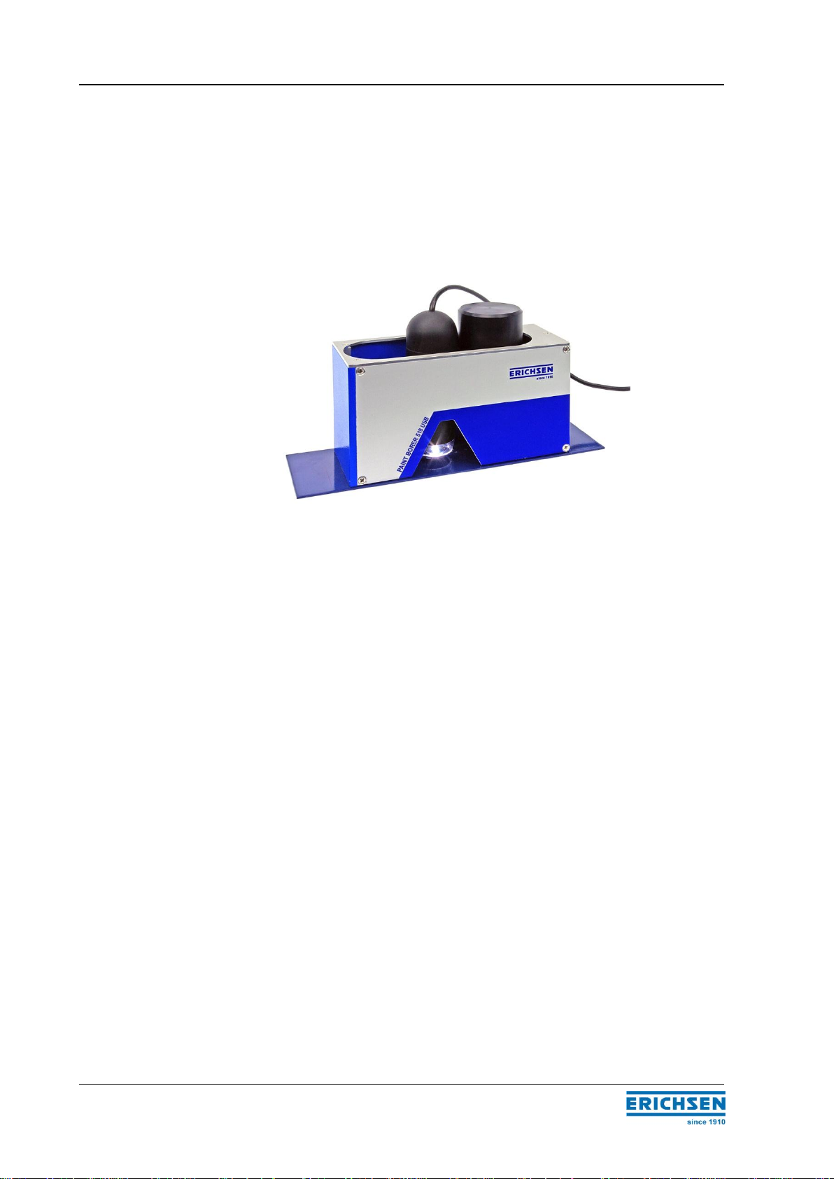
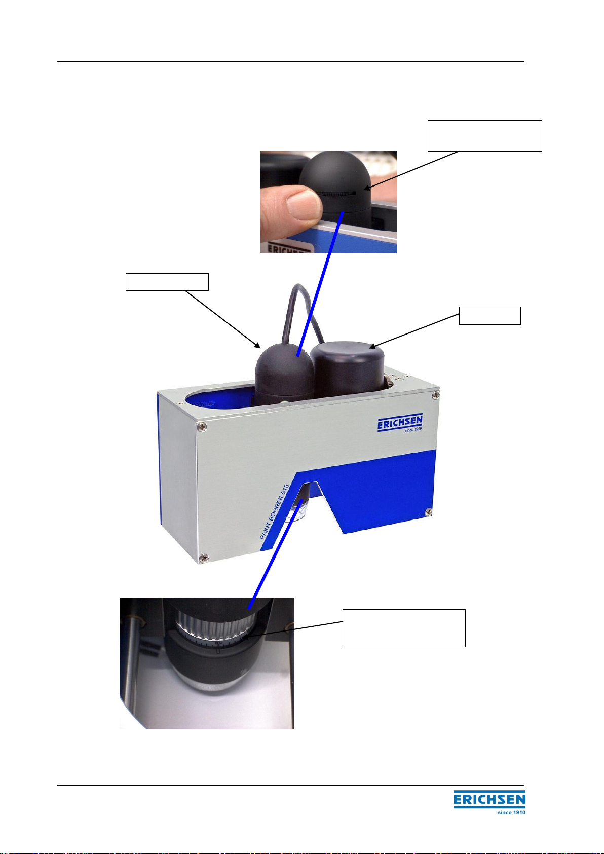
3 Commissioning –Operations –Handling
Drill
Digital microscope
Adjustment for the image
sharpness (the sharpness is
pre-set)
Knurled ring for adjusting
the lighting brightness

PAINT BORER 518 USB 8
BAE 518 USB
Battery compartment
Button (additional lighting)
Power supply
socket
PAINT BORER 518 USB 9
BAE 518 USB
3.1 Commissioning / driver and software installation
3.1.1 Minimum system requirements
PC laptop or tablet with WIN7, VISTA, WIN8, WIN8.1 or WIN10
Unused USB-2 port or USB-2 hub
4 GB of free space
Graphics: 1280 x 800
3.1.2 Camera driver
Connect the PC to the internet.
Connect the camera to a free USB-2 port.
The driver will be automatically downloaded and installed from the internet; follow the
instructions from your operating system if necessary.
Install the software after the message Device can be used is displayed.
3.1.3 Software installation
We have deliberately omitted an installer program to simplify file access and to minimize
OS dependencies.
Copy the Erichsen file (from the supplied USB flash drive) onto the C: drive or another
Windows partition.
Open the Erichsen folder.
Open the 518 folder.
Open the bin141 folder.
Select the 518.exe, right click and select "Send to -> Desktop (Create Shortcut)".
Repeat this procedure with the folder Protocols in the same directory.
The software program can be started directly from the desktop and the data can be
viewed by double-clicking on it.
If there is a network/software administrator at your company, contact him or her
for help.
The software runs directly from the included USB flash drive.
The space for logs is limited to the size of the USB flash drive.
PAINT BORER 518 USB 10
BAE 518 USB
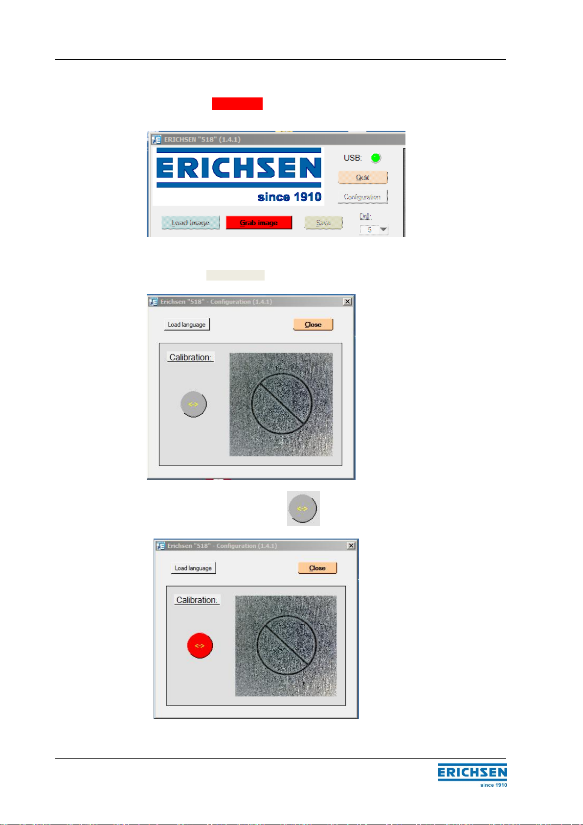
3.2 Commissioning and calibration
The calibration is only required for the initial commissioning and after the optical focusing.
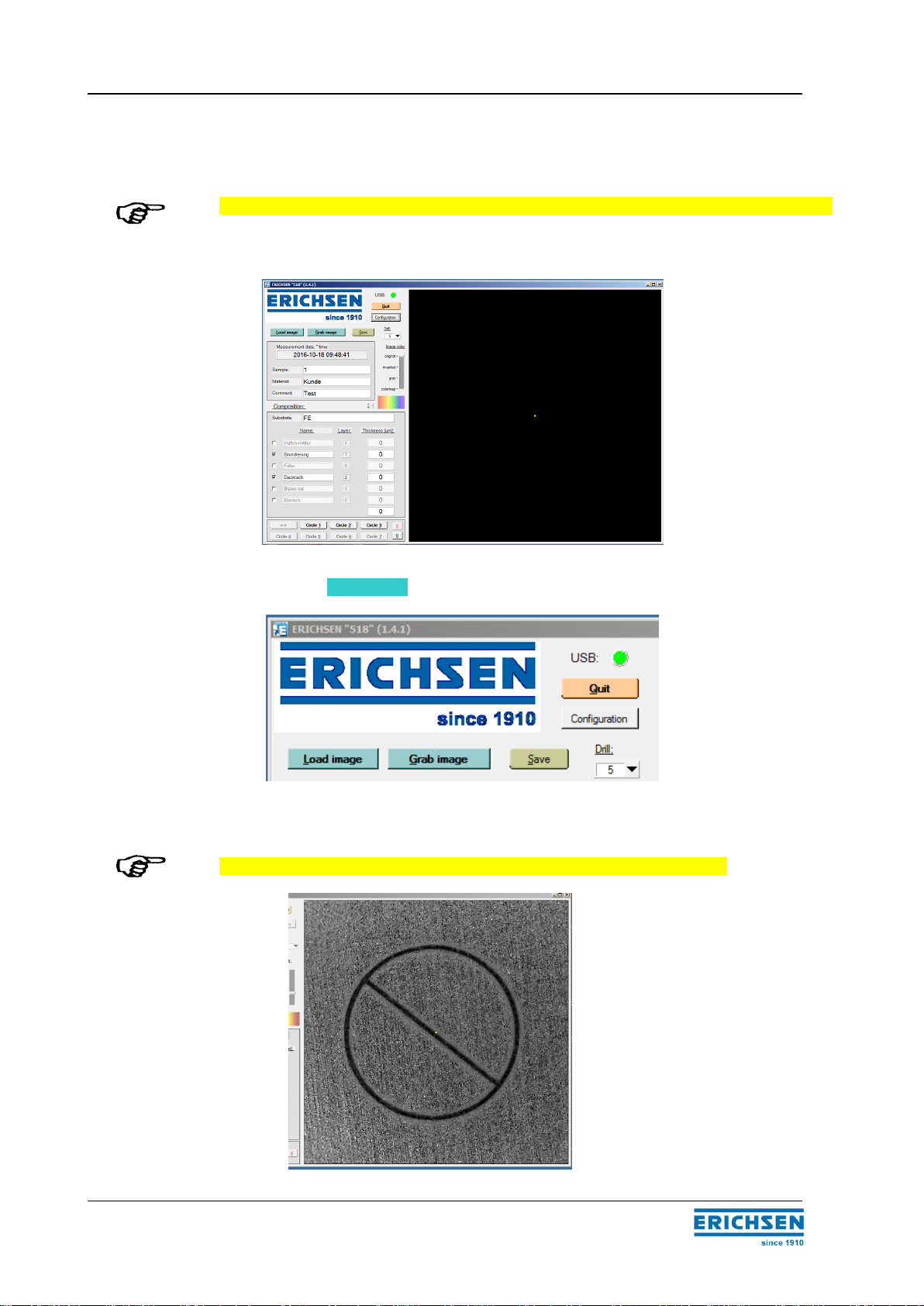
Start the program (main screen)
Click on the Grab image button (= live image)
Align the standard plate with the calibration circle in the middle.
The image must appear sharp; focus the sharpness before the calibration!
PAINT BORER 518 USB 11
BAE 518 USB
Click on the Grab image button again.
The image is now stored for calibration.
Click on the Configuration button. The configuration window opens.
Click on the Calibration button ; the button will now be colored red.
PAINT BORER 518 USB 12
BAE 518 USB
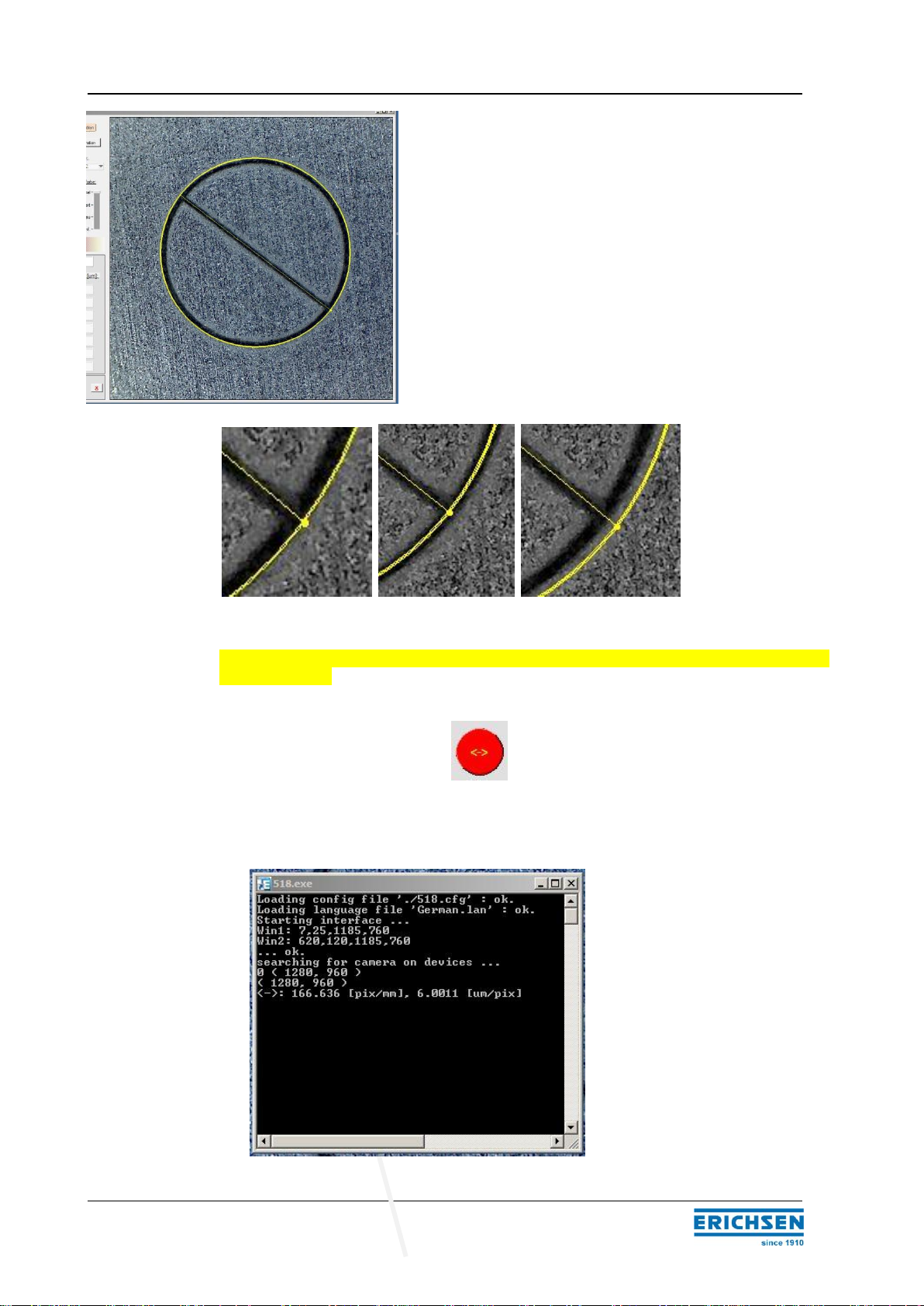
Use the mouse pointer and the left mouse button to
trace the edge of the calibration circle in the main
window.
correct wrong wrong
If the first attempt is not successful, you may retrace the circle with the left mouse button
until it is correct.
Click on the calibration button again. The calibration is finished.
Close the configuration window.
The calibration can be checked to see if it was successful from the control monitor.

PAINT BORER 518 USB 13
BAE 518 USB
The calibration value should be maintained between 5.0 and 6.0 microns.
For the vertical measurement of the drilled hole diameter, the resolution of the USB
camera is approximately 5.5 microns per pixel. (This can vary from 5 to 6 microns,
depending on the focus adjustment of the lens.)
The calibration of the USB microscope results in an average achievable resolution for
depth measurements of:
Drill 1 (0 –2000 microns): 5.5 microns
Drill 2 (0 –200 microns): 0.55 microns
Drill 3 (0 –1000 microns): 2.75 microns
Drill 4 (0 –500 microns): 1.375 microns
Drill 5 (0 –300 microns): 0.825 microns

PAINT BORER 518 USB 14
BAE 518 USB
3.3 Power supply
The PAINT BORER 518 USB can be operated in the field –when it is disconnected from
the mains power supply. A 9-volt NiCd rechargeable battery (IEC No. 6F22) can be used
as the internal voltage source. Alternatively, a 9-volt non-rechargeable battery (alkaline
type IEC No. 6LR61) may be used.
The 9-volt battery is delivered in a separate package; it must be inserted in the black
plastic compartment on the right side of the instrument before you start using the
instrument.
3.4 Lighting and auxiliary lighting
The lighting intensity can be adjusted using the knurled dial on the digital microscope.
Turn the dial to adjust the lighting intensity from 0 to 100%.
In this way you can adjust the illumination for the particular sample.
We recommend using a medium setting so that the lighting intensity can be adjusted in
both directions (lighter or darker) if needed.
When working with certain coatings, it may be helpful to also use indirect lighting.
For additional sample illumination, a white light emitting diode (LED) with diffuse light is
used.
The green button at the rear of the instrument can be pressed to activate the side lighting.
When switched on, the LED can be adjusted to three brightness levels.
The charging socket for connecting the AC adapter is located on the rear of
the PAINT BORER. The charging time is 14 hours. Measurements may be
taken during the charging phase even when the battery is not installed.
Do not connect the charger while you are operating the instrument with the
battery!
We recommend removing the battery if you are always using the PAINT
BORER with the mains power supply. Otherwise, the battery can be over-
charged.
If you are using the instrument in the field (with the battery) sporadically,
then the battery may be left inserted. However, the charger should not be
permanently connected.
Caution

PAINT BORER 518 USB 15
BAE 518 USB
Briefly press the button to turn on the LED. The mid-level brightness will be set
automatically after the LED is turned on.
The three levels of brightness can be switched on consecutively by repeatedly pressing
the button.
Press and hold the button to turn the LED off. The LED will also turn off automatically
after 60 seconds.
Example:
Grey plastic coating
without additional lighting with additional lighting
White top coating
without additional lighting with additional lighting
Colored coatings or multi-colored coating systems provide a higher contrast so that side
lighting is not necessary.
3.3 Setting the image focus
The image focus is pre-set.
If you still need to adjust the focus, the adjusting dial can be turned slightly to the left or
right to make adjustments.
! You will then need to carry out a calibration!

PAINT BORER 518 USB 16
BAE 518 USB
3.4 Slider mechanism
The slider is a key functional element of the PAINT BORER. It holds the drill apparatus
and the measuring microscope. The slider can be moved along a lengthwise guide so
that either the drill or the microscope is in the end position above the test point.
The slider is in the drill position when it is slid all the way to the left (left end stop).
By pressing down gently from above on the spring-loaded drill unit, it will lower and
simultaneously switch on the motor.
The right end stop position of the slider is the measurement position of the digital
microscope.
3.5 Wedge cut drill
(Refer to the table in section 2.3.2.)
The basic configuration of the PAINT BORER 518 USB includes a boring tool for the
measurement range of 300 microns (the No.5 drill). Additional drills are available as
accessories: for up to 200 microns (drill number 2), 500 microns (drill number 4), 1000
microns (drill number 1) and 2000 microns (drill number 3).
Drill number 1 has a single-edge cutting profile. Drills numbered 2, 3, 4 and 5 have a two-
edge cutting profile so that they can make proper conical bores at very shallow incidence
angles (5.7°, 8.5°, 14° or 26.7°).
All drills are made of solid hard metal (carbide) which is extremely wear-resistant but also
extremely brittle. Therefore, the drills should not be exposed to excessive shock
(especially when working on hard substrates).
In order to change the drill bit, loosen the clamping screw in the drill chuck (using the
screwdriver included with the delivery) and pull out the drill bit. Insert the new drill bit so
that it snaps into the coupling. Then tighten the clamping screw.
PAINT BORER 518 USB 17
BAE 518 USB
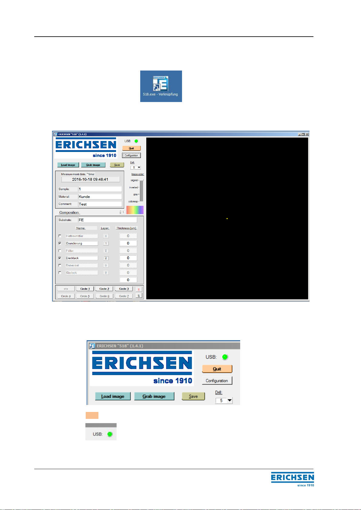
4 Program functions
1. Double click on to open the program.
2. The Main screen is shown below.
4.1 Menu and screen components
Quit: Exits the program.
Green: Connection to the camera is established.
Red: there is no connection.
PAINT BORER 518 USB 18
BAE 518 USB
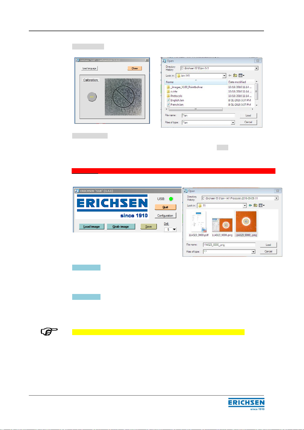
Configuration: Opens the window for calibration and for language selection.
Load language: Opens the window for selecting the language.
Select the desired *.lan (language) file and load it by clicking on Load.
The selected language will be activated after the program is restarted.
Calibration: Refer to page ... for instructions.
Load image: Loads a previously saved image.
The image can be edited as a newly captured image.
Grab image: Click on the Grab Image button once: a video image of the
measurement appears in the main window.
This enables you to position and process holes for which no image processing was
carried out.
Establishing the initial connection to the camera can take up to five seconds.
By default after the drilling is completed, the microscope is inserted and does not need to
be positioned.

PAINT BORER 518 USB 19
BAE 518 USB
The Grab image button is now colored red.
When the button is pressed again, the image is stored for processing and can be
measured.
"Measurement" is discussed separately on page 23 in section 5.3.
Save button: the measurement is saved and the log file is created.
4.2 Information about the sample
Measurement date and time: cannot be changed; the time setting is taken from the
system
Sample: can be edited
Material: can be edited
Comment: can be edited

PAINT BORER 518 USB 20
BAE 518 USB
4.3 Selection of drill and image color
4.3.1 Drill selection
You can select one of the five standard drills
(for example:drill number 5 is included in the delivery).
4.3.2 Image color
There are four modes available for displaying the image and image contrast
optimally.
False colors: There are 13 different variations that can be
chosen from the list of numbers .
It is very important to choose the proper drill for the measurement.
If the wrong drill is selected for the measurement, the incorrect angle will result
in a false measurement result.
Table of contents
Popular Measuring Instrument manuals by other brands


PCB Piezotronics
PCB Piezotronics 018C10 Installation and operating manual

Center
Center SE-323 instruction manual

SAEHAN
SAEHAN SH5002 user manual

BRONKHORST
BRONKHORST ES-FLOW 1 C Series instruction manual

Honeywell
Honeywell Enraf 977 instruction manual

enphase
enphase RGM Hardware installation and operation manual