Erie 2400TS Series User manual

A Division of Aquion, Inc.
2400TS
SERIES
Technical Manual

Table of Contents
Introduction.....................................................................Page 1
Technical Specifications.................................................Page 2
Flow Diagrams................................................................Page 3
Injector & Flow Control Selection....................................Page 4
Injector................................................................Page 4
Backwash flow control........................................Page 4
Brine refill flow control........................................Page 5
Installation
Assembly............................................................Page 6
Installation..........................................................Page 6
Installation check-out .........................................Page 7
Mixing valve .......................................................Page 7
The Electronic Timer
Basic features ....................................................Page 8
Programming......................................................Page 9
Diagnostics level................................................Page 12
Parts Replacement
Printed Circuit Board..........................................Page 14
Drive motor.........................................................Page 15
Injector................................................................Page 15
Backwash flow control........................................Page 16
Brine refill flow control........................................Page 16
Brine tee.............................................................Page 16
Rotor assembly ..................................................Page 16
Seal disk.............................................................Page 16
Gasket................................................................Page 17
Float valve..........................................................Page 17
Timer head assembly.........................................Page 17
Worm drive shaft................................................Page 17
Synchronising valve body and timer head .........Page 18
Troubleshooting..............................................................Page 20
Annual Maintenance.......................................................Page 23
Exploded Views & Part Numbers
Electronic timer ..................................................Page 24
Valve body .........................................................Page 26
Order Specifications .......................................................Page 28
Art. Nr.: Tech_Man-ENG-2400TS-2013.06

2400TS SERIES
Erie Water Treatment Controls – Belgium
Page 1
Introduction
The electronic 2400TS is a 4-cycle regeneration control valve for softening of drinking and feed water supplies.
The unique motor driven rotor assembly has a minimum of moving parts; together with the 1-piece Noryl® body,
this guarantees extremely high flow rates and exceptional reliability. The microprocessor controlled programmer
with NOVRAM®, offers unrivalled programming simplicity for use in time clock systems. The control valve is
designed for hard water bypass during regeneration. A built in adjustable blending device for mixing hard and soft
water to suit the particular needs of each installation, is a standard feature. The valve requires only an aircheck; a
conventional float-controlled brine valve system can be used as a double security. The following sequence is
followed:
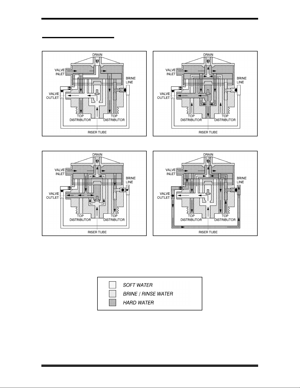
1. SERVICE:
Untreated water flows down through the resin bed and up through the riser tube; the water is conditioned when
passing through the resin. The throughput is dependent on the maximum permissible pressure drop for the
complete water softener and the maximum permissible specific load of the resin (generally taken as 40 litres
soft water per hour per litre resin).
2. BACKWASH:
Water flows down through the riser tube and up through the resin bed to drain; the resin bed is fully expanded
and all foreign materials are thoroughly washed from the resin, allowing a good brine cycle to occur.
3. BRINE:
Salt brine, drawn from the brine tank by the injector, slowly flows down through the resin bed and up through
the riser tube to drain; the resin is being regenerated when the salt brine passes through. The brine cycle is
terminated when the air check is shut.
4. SLOW RINSE:
Slow rinse continues for the remainder of the brine cycle; the injectors motive water slowly flows down through
the resin bed and up through the riser tube to drain, slowly washing the brine from the resin tank.
5. FAST RINSE/BRINE REFILL:
Water flows to the brine tank and at the same time down through the resin bed and up through the riser tube to
drain, ensuring that all traces of brine are washed out and that the resin bed is compacted. The resin bed is now
ready for the next service cycle.

2400TS SERIES
Erie Water Treatment Controls – Belgium
Page 2
Technical Specifications
Valve body material
Connections
- inlet/outlet (optional)
- drain line
- brine line
- tank
- riser tube
Mixing valve
Glass filled Noryl®
Brass adapters BSP, 3/4” male/female, 1” male
3/4” NPT with hose barb 13 mm
Compression fitting 3/8” polytube
2 1/2” - 8 NPSM
1,050” / 26,7 mm
Standard
Flow rates (valve with riser)
- service
- backwash
- fast rinse
Kv = 5,5 / Cv = 6,4
Kv = 1,7 / Cv = 2,0
Kv = 1,0 / Cv = 1,2
Application Softener 7” - 16”
Operating pressure
Operating temperature
Electrical rating
1,4 - 8,3 bar / 20 - 120 psi
2 - 48 °C / 35 - 120 °F
24V - 50 Hz, max. 400 mA
Regeneration
Controller
- software
- regeneration initiation
- regeneration type
- time of regeneration
- regeneration interval
- backwash
- brine draw/slow rinse
- fast rinse/brine refill
4 cycles, co-current brining
Electronic with µ-processor and NOVRAM®
EAZY
Time clock or manual
Delayed
Adjustable
Adjustable: OFF, 1 - 30 days
Adjustable: 0 - 20 min
Adjustable: 0 - 120 min
Adjustable: 0 - 65 min
2400TS SERIES
Erie Water Treatment Controls – Belgium
Page 3
Flow Diagrams
SERVICE BACKWASH
BRINE / SLOW RINSE FAST RINSE / BRINE REFILL

2400TS SERIES
Erie Water Treatment Controls – Belgium
Page 4
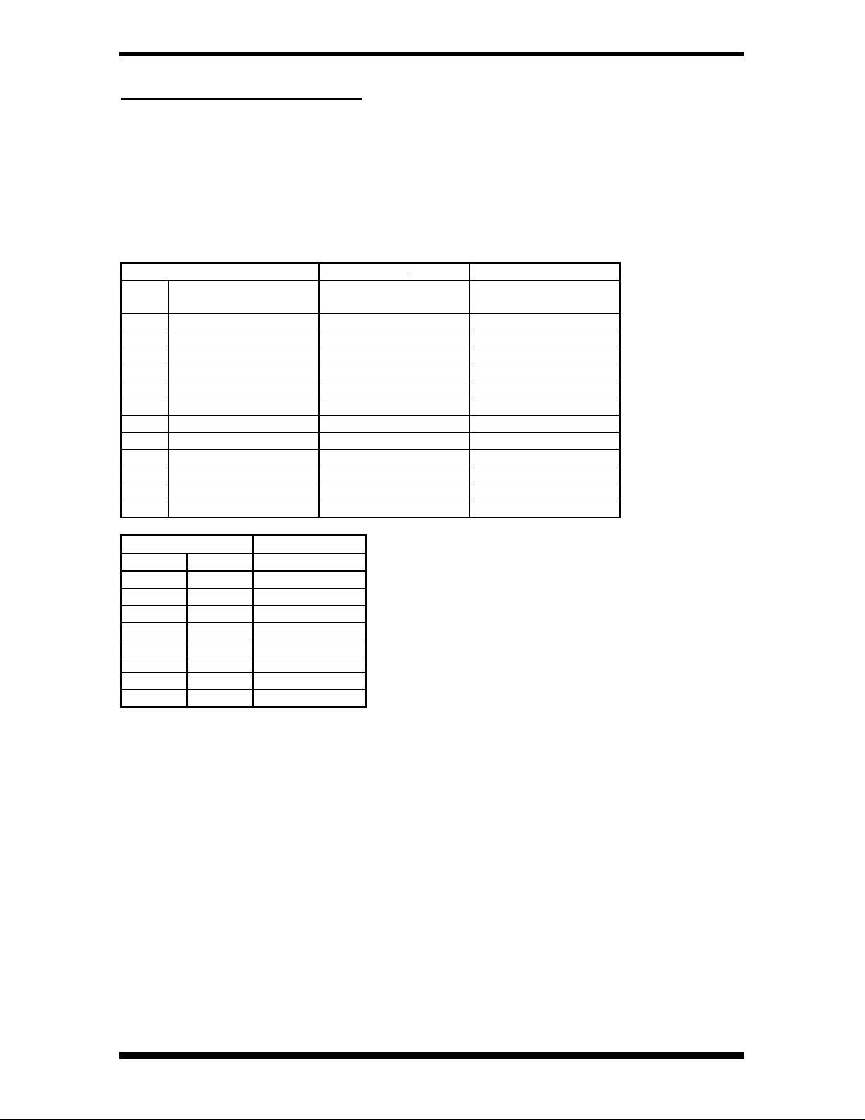
Injector & Flow Control Selection
Injector
The injector determines the brine concentration (ratio between brine suction and rinse water) and the brine flow
through the resin bed, thus the contact time between brine and resin. Injector performances vary significantly with
inlet pressure.
Press. Inj. 4 (PURPLE) Inj. 1 (RED) Inj. 2 (YELLOW) Inj. 5 (GREEN)
inlet Brine Rinse Brine Rinse Brine Rinse Brine Rinse
bar L/min L/min L/min L/min L/min L/min L/min L/min
1,38 0,64 0,72 1,32 1,21 1,63 1,86 1,14 3,14
2,07 0,64 0,91 1,63 1,40 1,97 2,08 1,48 3,56
2,76 0,64 0,98 1,82 1,51 2,23 2,27 1,70 3,94
3,45 0,68 1,06 2,01 1,63 2,42 2,46 1,97 4,28
4,14 0,68 1,17 2,04 1,78 2,61 2,65 2,20 4,58
!!! The following table is only an indication and is valid for an inlet pressure of 3 bar and a bed height of 30”.
Tank Injector
inch mm Nr. Colour
7 178 4 PURPLE
8 203 4 PURPLE
9 229 4 PURPLE
10 254 1-4 RED-PURPLE
12 305 1 RED
13 330 1 RED
14 356 2-1 YELLOW-RED
16 406 5-2 GREEN-YELLOW
Backwash flow control
The backwash flow control determines the resin bed expansion during backwash, independent of the inlet pressure.
The optimal bed expansion is generally obtained at a backwash flow of 1,8 L/min per dm2of resin bed surface.
Tank Backwash F.C.
inch mm Nr. Gal/min
(L/min)
7 178 E 1,6 (6,1)
8 203 E 1,6 (6,1)
9 229 G 2,0 (7,6)
10 254 J 2,6 (9,8)
12 305 K 3,5 (13,2)
13 330 L 4,0 (15,1)
14 356 M 5,0 (18,9)
16 406 N 6,0 (22,7)
2400TS SERIES
Erie Water Treatment Controls – Belgium
Page 5
Brine refill flow control
Together with the time of the fast rinse/brine refill cycle, the brine refill flow control determines
the quantity of refill to the brine tank, independent of the inlet pressure:
flow control x cycle time = quantity of refill
Do mind that the fast rinse/brine refill cycle can only be set by increments of 1 min!
!!! The following tables are only an indication and are valid for a brine valve with a refill rate that equals or
exceeds the rate of the refill flow control.
Brine refill F.C. Program: 3ecycle Quantity of refill
Nr. Gal/min
(L/min) min L (±10 %)
A 0,25 (1,0) 4 3,8
A 0,25 (1,0) 6 5,7
A 0,25 (1,0) 8 7,6
A 0,25 (1,0) 10 9,5
B 0,5 (1,9) 6 11,4
B 0,5 (1,9) 8 15,1
B 0,5 (1,9) 10 18,9
D 1,0 (3,8) 6 22,7
D 1,0 (3,8) 8 30,3
D 1,0 (3,8) 10 37,9
D 1,0 (3,8) 12 45,4
/ Kv = 0,27 / /
Tank Brine refill F.C.
inch mm Nr.
7 178 A-B
8 203 A-B
9 229 B
10 254 B-D
12 305 D
13 330 D
14 356 D
16 406 /

2400TS SERIES
Erie Water Treatment Controls – Belgium
Page 6
Installation
Assembly
For proper assembly of control valve and resin tank, proceed as follows:
1. Rinse the resin tank well before use.
2. Attach the lower distributor to the riser tube using PVC-glue or a stainless steel pin.
3. Lower the riser tube into the resin tank so that it touches the bottom.
4. Cut the riser tube 13 mm (= 1/2”) below the top of the tank threads and chamfer the tube to prepare for
insertion into the control valve.
5. Temporary plug the top of the riser tube to prevent resin from entering the tube and fill the tank with resin for
max. 3/4 full.
6. Make sure the O-ring in the riser insert of the control valve is in the correct position; screw the upper
distributor onto the control valve.
7. Lubricate the threads, the top of the riser tube and the tank O-ring of the control valve.
8. Lower the control valve straight down onto the riser tube and screw it onto the tank.
Installation
!!! ATTENTION
For proper functioning of the unit, incoming water pressure should be between a minimum of 1,4 bar during
regeneration and a maximum of 8,3 bar in service; if necessary, a pressure reducer must be installed ahead of
the system.
Installation must only be undertaken by a person competent in plumbing.
All plumbing and electrical connections must be done in accordance with local codes.
Do not install the unit too close to a water heater (min. 3 m of piping between outlet of unit and inlet of heater);
water heaters can sometimes transmit heat back down the cold pipe into the control valve; always install a
check valve at the outlet of the system.
If the control valve is not equipped with a bypass, a three valve bypass system must be installed to enable
bypassing during servicing.
For proper installation of the unit, proceed as follows:
1. Inlet/outlet: connect the inlet and outlet to the control valve; when facing the front of the control valve, the
inlet is at the left and the outlet at the right side.
2. Drain line: connect a hose to the drain line fitting on the control valve and secure it; insert the drain hose into
a standpipe, with siphon if required; make sure the drain hose is:
as short as possible,
not elevated too much,
free of kinks,
as this will all create undesired counter-pressure.
3. Brine line: an aircheck is required for proper brining during regeneration, but a float-controlled brine valve
system can be used as a double security; 3/8” polytube must be used to connect the brine system to the control
valve; do not overtighten the nut.
4. Transformer: make sure the power source carries the same rating as the transformer; plug transformers output
lead (with plug ø 2,5 mm x 5,5 mm) into socket at the timers power lead and plug transformer into socket; the
connection can be secured by means of the wire clip.

2400TS SERIES
Erie Water Treatment Controls – Belgium
Page 7
Installation check-out
When installation has been completed, the unit is ready to be placed into service. Proceed as follows, while
checking the unit for any leakages:
1. Place unit in bypass and turn on main water supply; open a cold water tap nearby and allow water to run for a
few minutes until all foreign material that may have resulted from the installation is washed out; close the tap.
2. Slowly shift the bypass valve to the service position and secure it; allow water to completely fill the resin tank.
3. Carefully open a cold water tap and allow water to run for at least 2 minutes to set the resin bed and purge air
from the unit; close the tap.
4. Program the control valve according to the specific installation (refer to “Programming” on pg. 11).
5. Push the scroll button until the display shows:
6. Leave the control valve in this position; the countdown timer will countdown to 0 sec and start a regeneration.
7. The motor will start and the display will show:
8. You can push the scroll button again to switch the motor to full speed, which will shorten the transfer time
needed by the control valve to reach the next position.
9. The motor will move the control valve into backwash position; allow water to run to drain until all of the air is
purged from the system.
10.Fill the brine tank with water, higher then the air-check level.
11.Push the scroll button; the motor will start and the display will show:
12.The motor will move the control valve into brine/slow rinse position; allow it to draw water from the brine tank
until the aircheck closes.
13.Push the scroll button; the motor will start and the display will show:
14.The motor will move the control valve into fast rinse/brine refill position; allow water to run to drain and brine
tank for the entire cycle time, to fill the brine tank to the programmed level.
15.Add salt to the brine tank.
Mixing valve
To adjust the residual hardness, the incorporated mixing valve must be regulated in function of the hardness of the
incoming water and the desired residual hardness
To increase the residual hardness: turn screw counter clockwise.
To decrease the residual hardness: turn screw clockwise.
Regen in 10 sec
Rgn:XX
Cyc1:YY
Rgn:XX
Cyc2:YY
Rgn:XX Cyc3:YY

2400TS SERIES
Erie Water Treatment Controls – Belgium
Page 8
scroll button up / down buttons
to advance to adjust the
through the value of the
parameters parameter
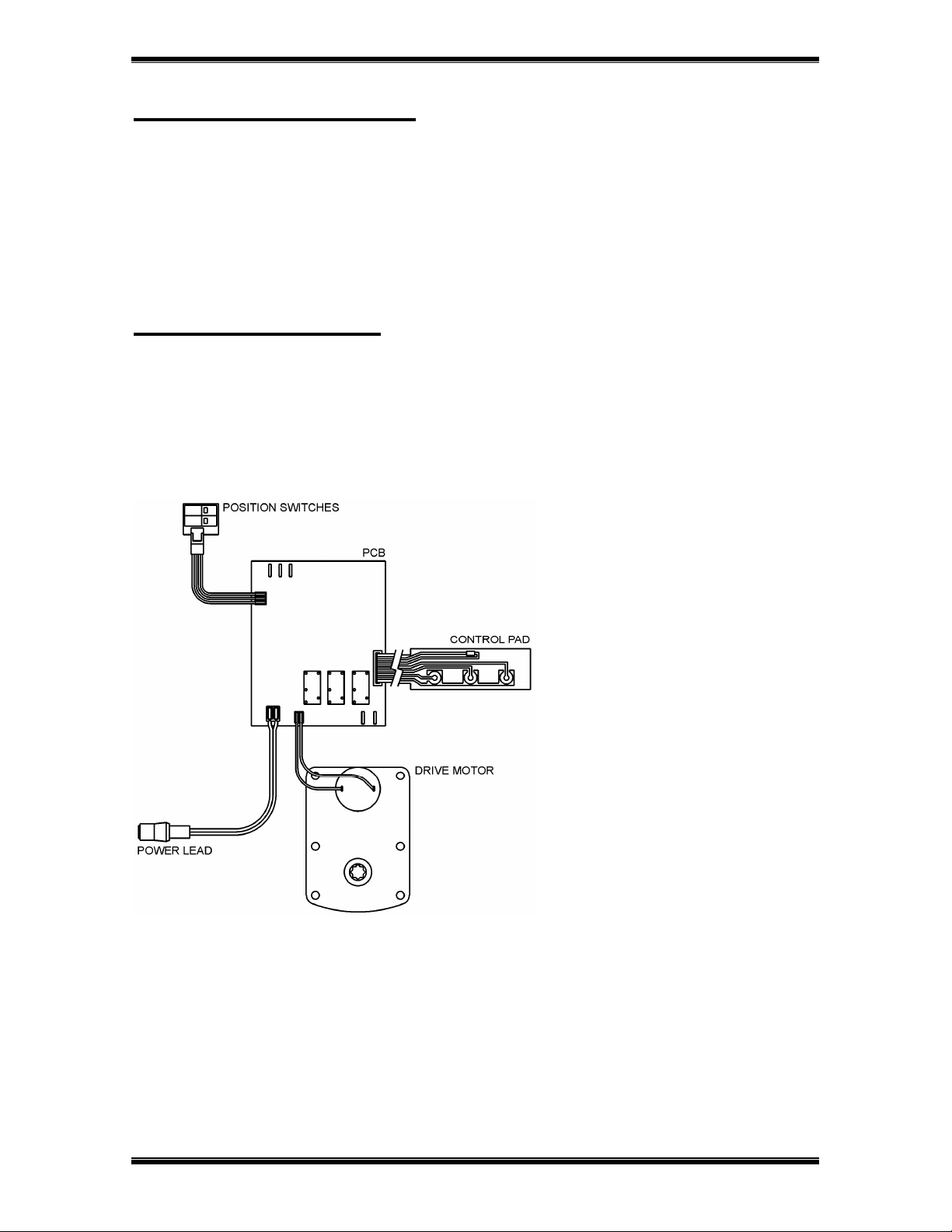
The Electronic Timer
Basic features
Control pad
The electronic timer uses a Printed Circuit Board (PCB),
equipped with a microprocessor and NOVRAM®. All
programming is done by use of the 3-button control pad
with LCD-display.
Service mode
In service mode the display shows the time of day and the number of days remaining until the next regeneration:
time of day days remaining
Regeneration mode
In regeneration mode the display shows the total remaining regeneration time, the actual regeneration cycle and
the remaining cycle time:
total remaining actual regen. remaining
regen. time cycle cycle time
The control valve can be reset to service mode at any time by pushing the scroll button, as such manually
advancing it through the regeneration cycles.
Power failure
In the event of a power failure, the program remains stored in the NOVRAM® during an undefined period, while
an incorporated SuperCap (capacitor) will maintain the correct time of day during a period of several hours;
consequently, in case of prolonged power failure, the time of day might not be maintained; if this happens, the time
of day indication will, when the power supply is re-established, be flashing, indicating that the time of day needs to
be set; refer to “Programming instructions for the End-User level” to set the correct time of day.
When the power failure occurs during the execution of an automatic regeneration, the control valve will remain in
it’s last position; when the power supply is re-established, the control valve will return to the service position, stay
there for 60 sec. and restart a complete regeneration from the beginning.
20:51 4 DAY REM
Regen 67
Cyc2:45

2400TS SERIES
Erie Water Treatment Controls – Belgium
Page 9
Timer failure
In the event of a timer failure, the display will show the message:
In such case, entering one of the programming levels can possibly solve the problem. However if the problem
persists, professional service is required.
Service Required

2400TS SERIES
Erie Water Treatment Controls – Belgium
Page 10
Programming
!!! ATTENTION
During programming, it is necessary to enter the desired change within 60 sec. Otherwise the microprocessor
will automatically break off the programming and return to the service mode, while all possibly entered
changes to the program are lost. If this occurs, it will be necessary to re-initiate the programming process.
All programming parameters are grouped into different user-specific levels (End-User / Parameter Set /
Diagnostics). The end-user level is accessible freely; in order to access one of the other specific levels, the
proper access code, i.e. key sequence, needs to be entered.
In the programming modes, a flashing indication implicates that this parameter can be adjusted by pushing the
up button or down button; in this technical manual this is indicated by means of an italic font.
Programming instructions for the End-User level
The basic configuration of the unit has been pre-programmed; the End-User level allows the end-user to rapidly
program the operating parameters, according to his own specific situation.
Make sure that the control valve is in the service mode.
Push the scroll button; the display will show:
Push the up button or down button to set the time of day.
Push the scroll button again; the display will show:
Push the up button or down button to set the number of days between regenerations.
Push the scroll button again; the display will show:
If the control valve is left in this position, the countdown timer will countdown to 0 sec and start a
regeneration.
To cancel this mode, push the scroll button before the countdown timer has reached 0 sec; the control
valve will return to the service mode.
Regen in 10 sec
Set time: 20:51
Interval:XX Days

2400TS SERIES
Erie Water Treatment Controls – Belgium
Page 11
Programming instructions for the Parameter Set level
In the Parameter Set level the basic configuration parameters of the unit can be programmed, depending on the
specific configuration of the unit.
Make sure that the control valve is in the service mode.
Push the scroll button and hold it for 5 sec until the display shows:
Within 10 sec, push the up button; the display will show:
Push the up button or down button to set the length of the backwash cycle from 0 to max. 20 min.
Push the scroll button again; the display will show:
Push the up button or down button to set the length of the brine/slow rinse cycle from 0 to max. 120
min.
Push the scroll button again; the display will show:
Push the up button or down button to set the length of the fast rinse/brine refill cycle from 0 to max.
65 min.
Push the scroll button again; the display will show:
Push the up button or down button to set the time of regeneration.
Push the scroll button again; the display will show:
Push the up button or down button to save the program to the NOVRAM® and exit the Parameter
Set level.
System Check
Cycle 1: 10 min
Exit
Regen @ 2:00
SENSOR 5:
XX
Cycle 2: 60 min
Cycle 3: 5min

2400TS SERIES
Erie Water Treatment Controls – Belgium
Page 12
Diagnostics level
Besides of all programming parameters, a series of operating parameters can be consulted in the diagnostics level;
particularly during a service intervention, these parameters can be helpful to identify the cause of a problem.
1. Accessing the Diagnostics level:
Make sure that the control valve is in the service mode.
Push the scroll button and hold it for 5 sec until the display shows:
Within 10 sec, push the down button; the display will show:
You are now in the Diagnostics level; use the scroll button to advance through the different diagnostics
parameters.
2. Exiting the Diagnostics level:
If no button is pushed within a time frame of 5 minutes, the microprocessor will exit the diagnostics level
end return to the service mode.
Push the scroll button until the display shows:
Push the up button or down button to exit the Diagnostics level.
3. Available diagnostic parameters:
In Srvc: displays show many days the unit has been in service.
# of Regens: display shows the number of regenerations that have taken place since installation.
MP Resets: display shows the number of resets of the microprocessor (for factory purpose only).
Memory Reset: display shows the number of corrupt memory start-ups (for factory purpose only).
EZ: display shows the software version (for factory purpose only).
System Check
Exit
In Srvc Xdays

2400TS SERIES
Erie Water Treatment Controls – Belgium
Page 13
2400TS SERIES
Erie Water Treatment Controls – Belgium
Page 14
Parts Replacement
!!! BEFORE SERVICING:
MAKE SURE THE CONTROL VALVE IS IN SERVICE POSITION
DISCONNECT ALL ELECTRICAL POWER TO THE UNIT
BYPASS OR DISCONNECT THE WATER SUPPLY
RELIEF THE WATER PRESSURE
Printed Circuit Board
1. Loosen the 3 front cover screws and remove the front cover.
2. Disconnect all connectors from the PCB.
3. Remove the flat cable of the 3-button control pad from the push-in connection on the PCB.
4. Remove the screws holding the PCB in place.
5. Push aside the clip holding the PCB in place and remove the PCB.
6. Reverse the procedure for reassembly; refer to wiring diagram for proper lead connections.

2400TS SERIES
Erie Water Treatment Controls – Belgium
Page 15
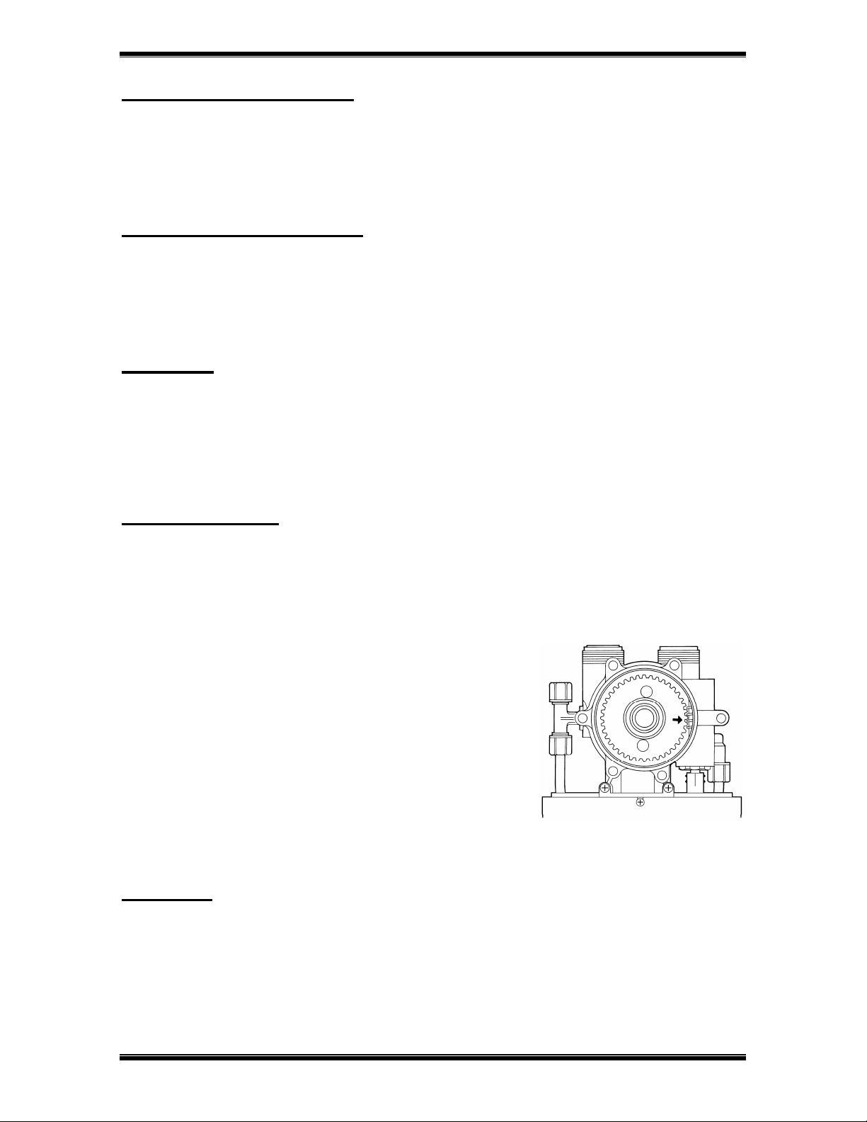
Drive motor
1. Remove the timer head assembly; refer to Parts Replacement “Timer head assembly”.
2. Loosen the 3 front cover screws and remove the front cover.
3. Disconnect the wire connector from the drive motor.
4. At the back of the back plate, remove the 2 screws holding the drive
motor assembly in place and remove the micro switch assembly and
drive motor.
5. Remove the retaining ring securing the worm and remove the worm
from the drive shaft.
6. Pull the drive shaft out of the drive motor.
7. Install the drive shaft in the drive motor, with the flat side on the drive
shaft pointing down (mark on the drive shaft pointing up (1)).
8. Install the worm on the drive shaft and install the retaining ring
securing the worm.
9. Put the micro switch assembly on the drive motor; make sure the switch
cam is in the service position (2).
10.Install the micro switch assembly and drive motor on the back plate
and secure it with the 2 screws.
11.Connect the wire connector on the drive motor; refer to wiring diagram
for proper connection.
12.It is now necessary to check the synchronisation of valve body and
timer head; refer to to Parts Replacement “Synchronising valve body
and timer head”.
Injector
1. Remove the drain hose from the drain elbow.
2. Remove the 6 bolts holding the valve body and cover
together.
3. Lift the valve cover away from the valve body.
4. Remove the rotor assembly from the valve cover; the white
Teflon O-ring will remain in the valve cover.
5. Remove the seal plate from the valve body.
6. Remove the insert plate and gasket from the valve body.
7. Using a needle nose pliers grasp one side of the injector and
pull the injector straight out of the valve body.
8. Make sure the float valve is straight up into the float chamber
of the valve body.
9. Install the insert plate and gasket in the valve body.
10.Lightly lubricate the O-rings of the new injector with a soap
water solution.
11.Install the injector with one of the rectangular openings on the injector facing directly towards the centre of the
valve body; push the injector firmly down.
12.Install the seal disk in the valve body, with the green side facing up.
13.Install the rotor assembly into the valve body ensuring that the
arrow on the worm gear is pointing directly towards the second
tooth on the worm drive shaft (facing the front of the control valve);
the 2 holes in the rotor assembly should now be exactly aligned with
the corresponding holes in the seal disk.
14.Centre the PVC sleeve on the worm gear.
15.Make sure the valve cover O-ring is clean and securely installed
around the raised rib on the valve cover.
16.Lower the valve cover straight down onto the valve body and press it
down firmly and evenly to seat the valve cover.
17.Install the 6 bolts and tighten them in a cross pattern.
18.Install the drain hose to the drain line fitting.
2400TS SERIES
Erie Water Treatment Controls – Belgium
Page 16
Backwash flow control
1. Remove the drain hose from the drain elbow and remove the drain elbow.
2. Unscrew the backwash flow control using a 3/8” Allen wrench.
3. Reverse the procedure for reassembly.
Brine refill flow control
1. Remove the clip securing the refill elbow.
2. Remove the brine refill flow control from the refill elbow.
3. Reverse the procedure for reassembly.
Brine tee
1. Remove the brine line and brine refill tube from the brine tee.
2. Remove the brine tee by turning it counter clockwise.
3. Remove the O-ring, the retainer and check ball from the brine tee.
4. Reverse the procedure for reassembly.
Rotor assembly
1. Remove the drain hose from the drain elbow.
2. Remove the 6 bolts holding the valve body and cover together.
3. Lift the valve cover away from the valve body.
4. Remove the rotor assembly from the valve cover; the white Teflon O-ring will remain in the valve cover.
5. Inspect the rotor plate’s surface; it should be smooth and free of any circular grooves or scratches; replace if
necessary.
6. Install the rotor assembly into the valve body ensuring that the
arrow on the worm gear is pointing directly towards the second
tooth on the worm drive shaft (facing the front of the control valve);
the 2 holes in the rotor assembly should now be exactly aligned with
the corresponding holes in the seal disk.
7. Centre the PVC sleeve on the worm gear.
8. Make sure the valve cover O-ring is clean and securely installed
around the raised rib on the valve cover.
9. Lower the valve cover straight down onto the valve body and press it
down firmly and evenly to seat the valve cover.
10.Install the 6 bolts and tighten them in a cross pattern.
11.Install the drain hose to the drain line fitting.
Seal disk
1. Remove the rotor assembly; refer to Parts Replacement “Rotor assembly”.
2. Remove the seal disk from the valve body.
3. Inspect the seal disk; make sure the raised ribs are intact; the green Teflon coating may be worn off of the ribs,
but this won’t affect the sealing performance of the seal disk; replace if necessary.
4. Use silicone base lubricant to lubricate the green side of the seal disk.
5. Install the seal disk in the valve body, with the green side facing up.
6. Reverse the procedure for reassembly; refer to Parts Replacement “Rotor Assembly”.

2400TS SERIES
Erie Water Treatment Controls – Belgium
Page 17
Gasket
1. Remove the seal disk; refer to Parts Replacement “Seal disk”.
2. Remove the insert plate and gasket from the valve body
3. Inspect the insert plate; make sure the ribs are intact.
4. Using a needle nose pliers grasp one side of the injector and
pull the injector straight out of the valve body.
5. Clean the surface of the valve body.
6. Make sure the float valve is straight up into the float chamber
of the valve body.
7. Install the insert plate and gasket in the valve body.
8. Install the injector with one of the rectangular openings on the
injector facing directly towards the centre of the valve body;
push the injector firmly down.
9. Reverse the procedure for reassembly; refer to Parts
Replacement “Seal disk”.
Float valve
1. Remove the gasket; refer to Parts Replacement “Gasket”.
2. Remove the float valve straight out of the float valve chamber of the valve body.
3. Remove the spring from the float valves shaft.
4. Clean all sealing surfaces inside of the float chamber.
5. Install the spring inside of the float valves shaft.
6. Install the float valve straight up into the float chamber of the valve body.
7. Reverse the procedure for reassembly; refer to Parts Replacement “Gasket”.
Timer head assembly
1. Remove the 2 back plate mount screws and take away the timer head assembly.
2. Reverse the procedure for reassembly.
Worm drive shaft
1. Remove the timer head assembly; refer to Parts Replacement “Timer head assembly”.
2. Unscrew the packing gland nut.
3. Remove the packing gland nut/worm drive shaft from the valve body.
4. Separate the packing gland nut from the worm drive shaft.
5. Inspect the worm drive shaft; the threads should not be deformed or damaged; replace if necessary.
6. Install the worm drive shaft in the valve body, by turning it clockwise as far as possible.
7. Lubricate the O-rings of the worm drive shaft.
8. Install the packing gland nut over the worm drive shaft and screw it into the valve body.
9. Install the timer head assembly to the valve body and tighten the 2 back plate mount screws.
10.It is now necessary to check the synchronisation of valve body and timer; refer to Parts Replacement
“Synchronising valve body and timer head”.

2400TS SERIES
Erie Water Treatment Controls – Belgium
Page 18
Synchronising valve body and timer head
To insure the proper operation of the control valve, valve body and timer head should be synchronised in the
service position. Proceed as follows:
Step 1: Timer head
1. Make sure that the control valve is in the service mode; if the control valve is in regeneration, push the scroll
button, thus manually advancing it through the regeneration cycles, until the display shows the time of day:
2. The flat side on the drive shaft should be pointing down (mark on
the drive shaft pointing up (1)); if this is not the case: refer to Parts
Replacement “Drive motor”.
Step 2: Valve body
1. Remove the drain hose from the drain elbow.
2. Remove the 6 bolts holding the valve body and cover together.
3. Lift the valve cover away from the valve body.
4. Make sure the arrow on the worm gear is pointing directly towards
the second tooth on the worm drive shaft (facing the front of the
control valve) (2); the 2 holes in the rotor assembly should now be
exactly aligned with the corresponding holes in the seal disk.
5. Make sure the valve cover O-ring is clean and securely installed around the raised rib on the valve cover.
6. Lower the valve cover straight down onto the valve body and press it down firmly and evenly to seat the valve
cover.
7. Install the 6 bolts and tighten them in a cross pattern.
8. Install the drain hose to the drain line fitting.
20:51 4 DAY REM
Table of contents
Other Erie Control Unit manuals


