Erie 541N Series User manual

541N
SERIES
Technical Manual

Table of Contents
Introduction .....................................................................Page 1
Technical Specifications..................................................Page 2
Flow Diagrams (541N18/541N19)..........................................Page 3
Flow Diagrams (541N94/541N99)..........................................Page 4
Injector & Flow Control Selection
Injector................................................................Page 5
Drain flow control (optional)................................Page 5
Installation
Assembly............................................................Page 6
Installation ..........................................................Page 6
Installation check-out..........................................Page 7
Mixing valve (optional)........................................Page 7
Drain flow adjuster..............................................Page 8
Electronic Control panel..................................................Page 10
Programming......................................................Page 12
Diagnostics level ................................................Page 15
Parts Replacement
Printed Circuit Board ..........................................Page 16
Drain solenoid ....................................................Page 16
Backwash/refill solenoid .....................................Page 17
Backwash/refill solenoid diaphragm ...................Page 17
Valve head .........................................................Page 17
Injector................................................................Page 17
Brine draw restrictor ...........................................Page 18
Incorporated drain flow control (optional) ...........Page 18
Main diaphragm..................................................Page 18
Body stem assembly ..........................................Page 19
Check disc..........................................................Page 19
Riser insert .........................................................Page 19
Flow meter turbine..............................................Page 20
Troubleshooting ..............................................................Page 22
Annual Maintenance .......................................................Page 25
Exploded Views & Part Numbers
Electronic timer...................................................Page 26
Valve body 541N18 ............................................Page 28
Valve body 541N19 ............................................Page 30
Valve body 541N94 ............................................Page 32
Valve body 541N99 ............................................Page 34
Order Specifications 541N18 ..........................................Page 36
Order Specifications 541N19 ..........................................Page 37
Order Specifications 541N94 ..........................................Page 38
Order Specifications 541N99 ..........................................Page 39
Art. Nr.: TM-EN-541N-2011.09

541N SERIES
Erie Water Treatment Controls – Belgium
Page 1
Introduction
The 541N Series are electronic 2- or 4-cycle regeneration control valves for softening of drinking and feed water
supplies. When the drain solenoid is activated, the valve is automatically transferred to the regeneration position;
together with the optional additional solenoid valve(s) integrated in the back cap of the control valve body, this
simple and reliable system guarantees years of trouble-free service. The microprocessor controlled programmer with
NOVRAM®, offers unrivalled programming simplicity for use in demand initiated with days override systems. The
valve is designed for hard water bypass during regeneration. A built in adjustable blending device for mixing hard
and soft water to suit the particular needs of each installation is an optional feature. The 541N18 and 541N19 control
valves require a conventional float-controlled brine valve with aircheck to control the brine refill. The 541N94 and
541N99 require only an aircheck; a conventional float-controlled brine valve system can be used as a double
security. The following sequence is followed:
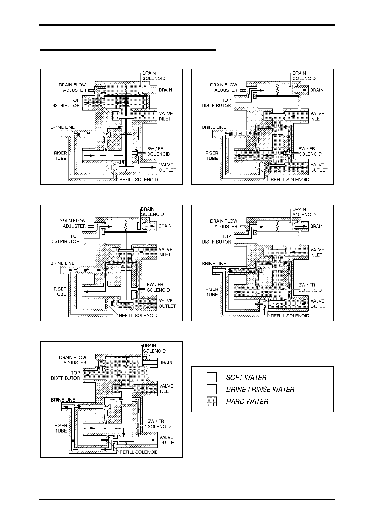
1. SERVICE:
Untreated water flows down through the resin bed and up through the riser tube; the water is conditioned when
passing through the resin. The throughput is dependent on the maximum permissible pressure drop for the
complete water softener and the maximum permissible specific load of the resin (generally taken as 40 litres soft
water per hour per litre resin).
2. BACKWASH (541N18/N94):
Water flows down through the riser tube and up through the resin bed to drain; the resin bed is fully expanded
and all foreign materials are thoroughly washed from the resin, allowing a good brine cycle to occur.
3. BRINE DRAW:
Salt brine, drawn from the brine tank by the injector, flows down through the riser tube and slowly up through
the resin bed to drain; the resin is being regenerated when the salt brine passes through. The brine draw cycle is
terminated when the air check is shut.
4. SLOW RINSE:
Slow rinse continues for the remainder of the cycle; the injectors motive water flows down through the riser tube
and slowly up through the resin bed to drain, slowly washing the brine from the resin tank.
5. FAST RINSE (541N18/N94):
Water flows down through the riser tube and up through the resin bed to drain, ensuring that all traces of brine
are washed out. The resin bed is now ready for the next service cycle.
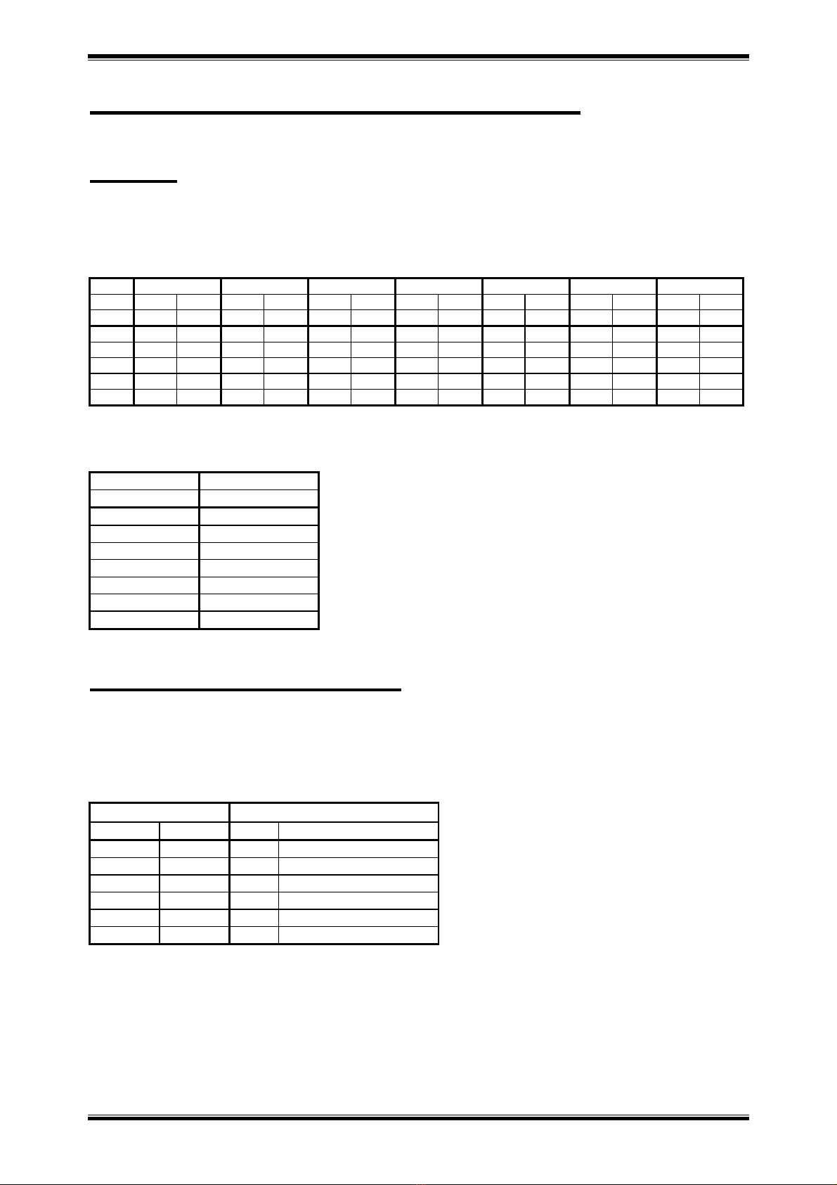
6. REFILL (541N94/N99):
With the valve back in the service position, soft water flows to the brine tank at a fixed flow of 1 L/min, and this
for a programmable duration.

541N SERIES
Erie Water Treatment Controls – Belgium
Page 2
Technical Specifications
Valve body material
Connections
- inlet/outlet
- drain line
- brine line
- tank
- riser tube
Mixing valve
Glass filled Noryl®
Brass adapters BSP, 3/4” male/female
, 1” male
1/2” NPT with hose barb 13 mm
Compression fitting 3/8” polytube
2 1/2” - 8 NPSM
1,050” / 26,7 mm
Optional
Flow rates (valve with riser)
- service
- backwash (541N18/N94)
- fast rinse (541N18/N94)
Kv= 4,1 / Cv= 4,8
Kv= 0,7 / Cv= 0,8
Kv= 0,7 / Cv= 0,8
Application Softener 6” - 12”
Operating pressure
Operating temperature
Electrical rating
1,4 - 8,3 bar / 20 - 120 psi
2 - 48 °C / 35 - 120 °F
24V - 50 Hz, max. 966 mA (541N18/N94)
24V - 50 Hz, max. 676 mA (541N99)
24V - 50 Hz, max. 326 mA (541N19)
Regeneration
Controller
- software
- regeneration initiation
- regeneration mode
- time of regeneration
- days override
- water hardness
- reserve capacity
- backwash (541N18/N94)
- brine draw/slow rinse
- fast rinse (541N18/N94)
- refill (541N94/N99)
4 cycles, counter-current brining (541N18/N94)
2 cycles, counter-current brining (541N19/N99)
Electronic with µ-processor and NOVRAM®
EAZY
Demand with days override or manual
Delayed, immediate or delayed with immediate
override
Adjustable
Adjustable: OFF, 1 - 30 days
Adjustable: 1 - 99 °f / °d / °Clarck
Self-calculating or adjustable (0-70% of total cap.)
Adjustable: 0 - 20 min
Adjustable: 0 - 180 min
Adjustable: 0 - 20 min
Adjustable: 0 - 65 min (@ 1 L/min)
Flow meter accuracy 1,4 - 115 L/min: ±10%

541N SERIES
Erie Water Treatment Controls – Belgium
Page 3
Flow Diagrams (541N18/N19)
SERVICE BACKWASH (541N18)
BRINE DRAW / SLOW RINSE FAST RINSE (541N18)
541N SERIES
Erie Water Treatment Controls – Belgium
Page 4
Flow Diagrams (541N94/541N99)
SERVICE BACKWASH (541N94)
BRINE DRAW / SLOW RINSE FAST RINSE (541N94)
BRINE REFILL
541N SERIES
Erie Water Treatment Controls – Belgium
Page 5
Injector & Flow Control Selection
Injector
The injector determines the brine concentration (ratio between brine suction and rinse water) and the brine flow
through the resin bed, thus the contact time between brine and resin. Injector performances vary significantly with
inlet pressure.
Inlet Inj. 9 Inj. 8 Inj. 5 Inj. 4 Inj. 3 Inj. 2 Inj. 1
press. Brine Rinse Brine Rinse Brine Rinse Brine Rinse Brine Rinse Brine Rinse Brine Rinse
bar l/min l/min l/min l/min l/min l/min l/min l/min l/min l/min l/min l/min l/min l/min
1,38 0,15 0,68 0,23 0,68 0,38 0,68 1,14 1,14 1,14 1,51 1,14 2,27 1,14 2,65
2,76 0,26 0,95 0,42 0,95 0,76 0,95 1,51 1,51 1,89 1,89 1,89 3,03 1,89 3,79
4,14 0,30 1,10 0,45 1,10 1,14 1,10 1,89 1,51 2,27 2,27 2,27 3,03 2,27 4,92
5,52 0,30 1,25 0,45 1,25 1,32 1,25 2,08 2,46 2,27 2,84 2,46 3,97 2,46 5,49
6,90 0,30 1,40 0,45 1,40 1,51 1,40 2,08 2,65 2,27 3,03 2,65 4,16 2,65 6,06
!!! The following table is only an indication and is valid for an inlet pressure of 3 bar, a bed height of 30” and
a salt consumption of 120-150 gr/l resin.
Resin volume
Injector
Liter
Nr.
< 8
9
8
–
15
8
15
–
20
5
20
–
30
4
30
–
40
3
40
–
50
2
> 50
1
Drain flow control (optional)
The drain flow control determines the resin bed expansion during backwash (541N18 and 541N94 only),
independent of the inlet pressure. The optimal bed expansion is generally obtained at a backwash flow of 1,8 L/min
per dm2of resin bed surface. In case of the 541 valve, it also helps to keep the piston in the regeneration position
when the operating pressure is extremely low (< 1,5 bar).
Tank
Drain F.C.
inch
mm
Nr.
Gal/min (l/min)
6
152
U
1,2 (4,5)
7
178
U
1,2 (4,5)
8
203
E
1,6 (6,1)
9
229
G
2,0
(7,6)
10
254
J
2,6 (9,8)
12
305
K
3,5 (13,2)

541N SERIES
Erie Water Treatment Controls – Belgium
Page 6
Installation
Assembly
For proper assembly of the control valve and resin tank, proceed as follows:
1. Rinse the resin tank well before use.
2. Attach the lower distributor to the riser tube using PVC-glue or a stainless steel pin.
3. Lower the riser tube into the resin tank so that it touches the bottom.
4. Cut the riser tube 13 mm (= 1/2”) below the top of the tank threads and chamfer the tube to prepare for insertion
into the control valve.
5. Temporary plug the top of the riser tube to prevent resin from entering the tube and fill the tank with resin for
max. 3/4.
6. Make sure the O-ring in the riser insert of the control valve is in the correct position; screw the upper distributor
onto the control valve.
7. Lubricate the threads, the top of the riser tube and the tank O-ring of the control valve.
8. Lower the control valve straight down onto the riser tube and screw it onto the tank.
Installation
!!! ATTENTION
For proper functioning of the unit, incoming water pressure should be between a minimum of 1,4 bar during
regeneration and a maximum of 8,3 bar in service; if necessary, a pressure reducer must be installed ahead of the
unit.
Installation must only be undertaken by a person competent in plumbing.
All plumbing and electrical connections must be done in accordance with local codes.
Do not install the unit too close to a water heater (min. 3 m of piping between outlet of unit and inlet of heater);
water heaters can sometimes transmit heat back down the cold pipe into the control valve; always install a check
valve at the outlet of the unit.
If the control valve is not equipped with a bypass, a three valve bypass system must be installed to enable
bypassing during servicing.
For proper installation of the unit, proceed as follows:
1. Inlet/outlet: connect the inlet and outlet to the elbows on the control valve; when facing the front of the valve,
the inlet is at the right and the outlet at the left side.
2. Drain line: connect a hose to the drain solenoid on the control valve and secure it; insert the drain hose into a
standpipe, with siphon if required; make sure the drain hose is:
as short as possible,
not elevated too much,
free of kinks,
as this will all create undesired counter-pressure.
3. Brine line: the 541N18 and 541N19 control valves require a conventional float-controlled brine valve with
aircheck to control the brine refill. The 541N94 and 541N99 require only an aircheck; a conventional float-
controlled brine valve system can be used as a double security. 3/8” polytube must be used to connect the brine
system to the control valve’s brine elbow.
4. Transformer: make sure the power source carries the same rating as the transformer; plug transformers output
lead (with plug ø 2,5 mm x 5,5 mm) into socket at the timers power lead and plug transformer into socket; the
connection can be secured by means of the wire clip.

541N SERIES
Erie Water Treatment Controls – Belgium
Page 7
Installation check-out
When installation has been completed, the unit is ready to be placed into service. Proceed as follows, while checking
the unit for any leakages:
1. Place unit in bypass and turn on main water supply; open a cold water tap nearby and allow water to run for a
few minutes until all foreign material that may have resulted from the installation is washed out; close the tap.
2. Slowly shift the bypass valve to the service position and secure it; allow water to completely fill the resin tank.
3. Carefully open a cold water tap and allow water to run for at least 2 minutes to set the resin bed and purge air
from the unit; close the tap.
4. Program the control valve according to the specific installation (refer to “Programming” on pg. 10).
5. Fill the brine tank with water, higher then the air-check level.
6. Press the scroll button until the display shows:
7. Leave the control valve in this position; the countdown timer will countdown to 0 sec and start a regeneration.
8. The drain solenoid will be activated and the display will show:
9. Check the correct functioning of the control valve in the different regeneration cycles; the control valve can be
advanced to the next regeneration cycle manually by pressing the scroll button.
541N18
541N19
541N94
541N99
Action
Backwash
Cycle 1
/
Cycle 1
/
p
urge air from system
Brine
draw
/slow rinse
Cycle 2
Cyc
le 1
Cycle 2
Cycle 1
draw water from the
brine tank until the
air check closes
Fast rinse
Cycle 3
/
Cycle 3
/
c
heck drain line for
flow
Brine refill
/
/
Cycle 4
Cycle 2
a
llow water to run to
brine tank for the
entire cycle time
10. Add salt to the brine tank.
For 541N18/541N19 only:
11. As soon as the control valve is back in the service position, place unit in bypass.
12. Add the appropriate amount of water to the brine tank.
13. Set float of brine valve to the level of the water in the brine tank.
14. Shift bypass valve back to the service position.
Mixing valve (optional)
To adjust the residual hardness, the incorporated mixing valve must be regulated in function of the hardness of the
incoming water and the desired residual hardness; the scale on the mixing valve has no absolute indication, but
serves only as a reference point:
To increase the residual hardness: turn screw counter clockwise.
To decrease the residual hardness: turn screw clockwise.
Regen in 10 sec
Rgn:XX Cyc1:YY
541N SERIES
Erie Water Treatment Controls – Belgium
Page 8
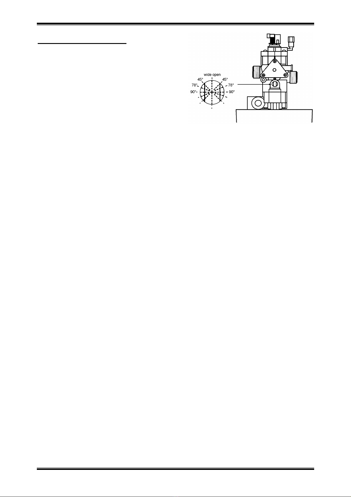
Drain flow adjuster
!!! ATTENTION
When the valve is equipped with an incorporated drain
flow control (optional), the drain flow adjuster is
assembled and locked in the wide open position! By
releasing the locking screw of the locking plate, the drain
flow adjuster can still be used, but note that the maximum
flow to drain is limited by the incorporated drain flow
control (optional).
With the drain flow adjuster it is possible to adjust the water flow to drain during regeneration. This way the water
consumption during backwash and fast rinse can be tuned for the system’s size. The optimal bed expansion during
backwash, is generally obtained at a backwash flow of 1,8 L/min per dm2of resin bed surface (depending on the
type of resin). To adjust:
1. Place the unit in backwash position.
2. Check the flow to drain.
3. Adjust the flow to drain by turning the drain flow adjuster either to the right or to the left, until the
desired drain flow is obtained.
Also, the so created counter pressure helps to keep the piston of the valve in the regeneration position when the
operating pressure is extremely low (< 1,5 bar). To adjust:
1. Place the unit in brine/slow rinse position.
2. Turn the drain flow adjuster either to the right or to the left until the piston remains stable in the
regeneration position.
Do note that closing the drain flow adjuster too much, will result in bad suction of the injector.

541N SERIES
Erie Water Treatment Controls – Belgium
Page 9
541N SERIES
Erie Water Treatment Controls – Belgium
Page 10
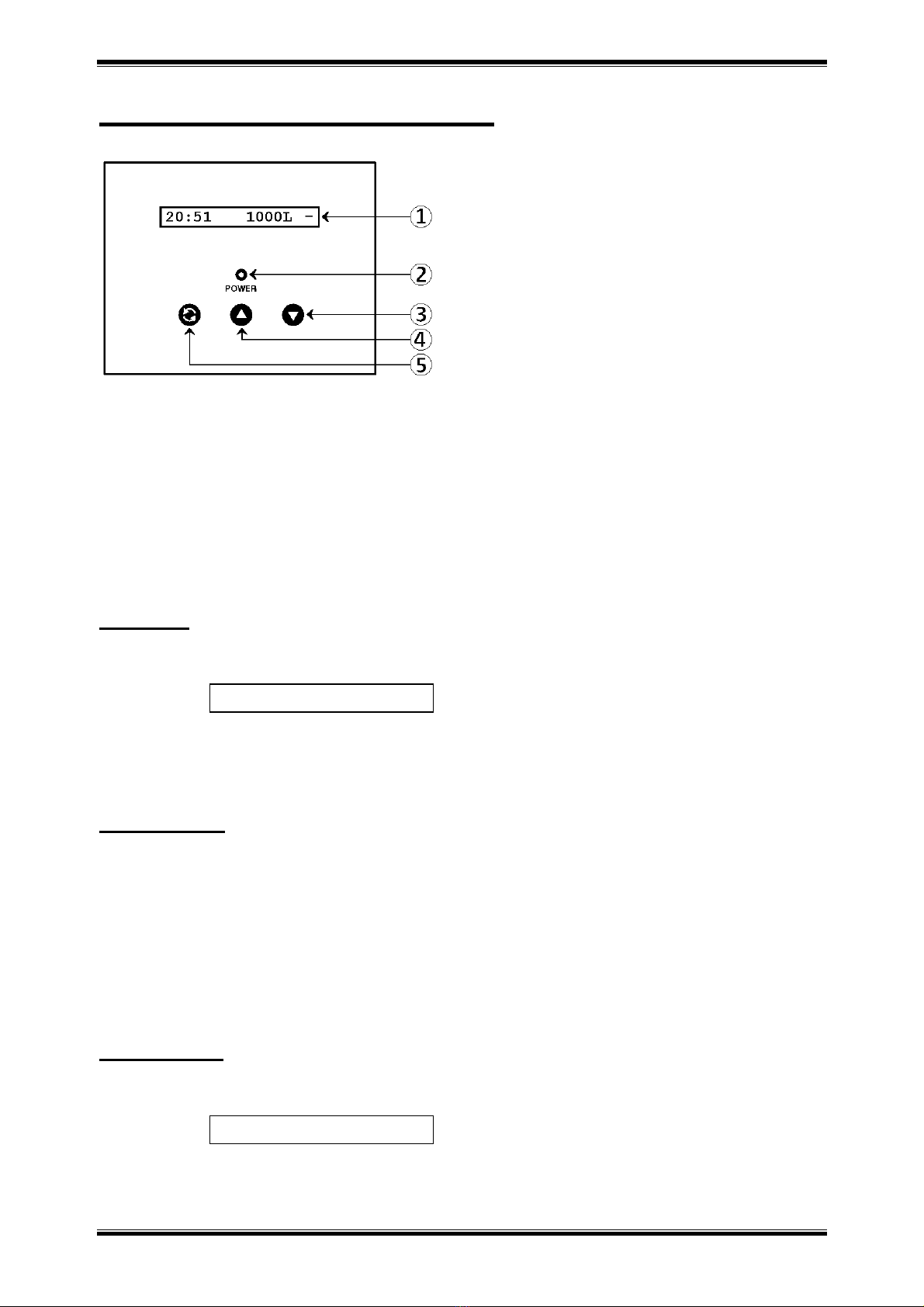
Electronic Control Panel
display
POWER led: lights up when electrical power is applied
DOWN button: to decrease the value of the parameter
UP button: to increase the value of the parameter
SCROLL button: to advance to the next parameter
Power-up
After power-up, the display will show the installed software version for 5 seconds, f.e.:
Afterwards it will automatically revert back to the service display.
The POWER led will light up.
Power failure
In the event of a power failure, the program will remain stored in the NOVRAM® during an undefined period, while
an incorporated SuperCap (capacitor) will maintain the correct time of day during a period of several hours;
consequently, in case of prolonged power failure, the time of day might not be maintained; if this happens, the time
of day indication will flash when the power supply is re-established, indicating that the time of day needs to be set.
When the power failure occurs during the execution of an automatic regeneration, the control valve will
immediately return to the service position; when the power supply is re-established, the control valve will stay in the
service position for 60 sec. and restart a complete regeneration from the beginning.
Timer failure
In the event of a timer failure, the display will show the message:
In such case, entering one of the programming levels can possibly solve the problem. However if the problem
persists, professional service is required.
EZDSDg EZ
Service Required
541N SERIES
Erie Water Treatment Controls – Belgium
Page 11
Service mode
In service mode the display shows the time of day, the remaining capacity and the water usage indicator:
Every day the control valve automatically recalculates the reserve capacity, as a progressing average. Permanently it
compares the remaining capacity with the calculated reserve capacity; as soon as the remaining capacity equals the
calculated reserve capacity, the display will show the time of day and the indication “REGEN”, indicating that a
delayed regeneration will be started at the pre-programmed time of regeneration:
In case the resin bed is fully exhausted (remaining capacity equals zero) before a delayed regeneration can take
place, the unit will regenerate immediately.
Regeneration mode
In regeneration mode the display shows the total remaining regeneration time, the actual regeneration cycle and the
remaining cycle time:
total remaining actual regen. remaining
regen. time cycle cycle time
The control valve can be reset to service mode at any time by pressing the scroll button, as such manually
advancing it through the regeneration cycles.
Checking the flow meter
In case of water usage, the remaining capacity counter in the service display will count back per unit, i.e. per litre;
furthermore the water usage indicator will revolve. This way the correct functioning of the water meter can be
verified.
Manual regeneration
It is possible to manually initiate a rgeneration.
1. Press the scroll button repeatedly until the display shows:
If the control valve is left in this position, the countdown timer will countdown to 0 sec and start a
regeneration.
To cancel this mode, press the scroll button before the countdown timer has reached 0 sec; the control
valve will return to the service mode.
20:51 1000L -
20:51
REGEN-
Regen in 10 sec
Rgn: 67
Cyc2: 45

541N SERIES
Erie Water Treatment Controls – Belgium
Page 12
Programming
!!! ATTENTION
During programming, it is necessary to enter the desired change within 60 sec. Otherwise the microprocessor
will automatically break off the programming and return to the service mode, while all possibly entered changes
to the program are lost. If this occurs, it will be necessary to re-initiate the programming process.
All programming parameters are grouped into different user-specific levels (End-User / Parameter Set /
Diagnostics). The end-user level is accessible freely; in order to access one of the other specific levels, the
proper access code, i.e. key sequence, needs to be entered.
In the programming modes, a flashing indication implicates that this parameter can be adjusted by pressing the
up button or down button; in this technical manual this is indicated by means of an italic font.
Programming instructions - End-User level
Before entering the programming mode, make sure that the control valve is in the service mode.
1. Press the scroll button; the display will show:
Press the up button or down button to set the language.
2. Press the scroll button again; the display will show:
Press the up button or down button to set the time of day.
3. Press the scroll button again; the display will show:
Press the up button or down button to set the water hardness of the incoming untreated water.
Language:English
Set time: 20:51
Set hardn.: XX°f
541N SERIES
Erie Water Treatment Controls – Belgium
Page 13
Programming instructions - Parameter Set level
In the Parameter Set level the basic configuration parameters of the unit can be programmed, depending on the
specific configuration of the unit.
Before entering the programming mode, make sure that the control valve is in the service mode.
1. Press the scroll button and hold it for 5 sec until the display shows:
2. Within 10 sec, press the up button; the display will show:
Press the up button or down button to set the units of hardness.
3. Press the scroll button again; the display will show:
Press the up button or down button to set the exchange capacity per litre of resin.
4. Press the scroll button again; the display will show:
Press the up button or down button to set the volume of resin.
5. Press the scroll button again; the display will show:
Press the up button or down button to set the number of days between regenerations.
6. Press the scroll button again; the display will show:
Press the up button or down button to set the length of the regeneration cycle.
541N18
541N19
541N94
541N99
Setting range
Backwash
Cycle 1
/
Cycle 1
/
0
-
2
0 min
Brine
draw
/slow rinse
Cycle 2
Cycle 1
Cycle 2
Cycle 1
0
-
1
8
0 min
Fast rinse
Cycle 3
/
Cycle 3
/
0
-
20 min
Brine refill
@ 1 L/min
/
/
Cycle 4
Cycle 2
0
-
65 min
7. Press the scroll button again; the display will show:
Press the up button or down button to set the model of flow meter used:
-SNAP SENSOR: model with snap-on flow meter sensor.
-SCREW SENSOR: model with sensor fixed by means of screw.
System Check
Cycle 1: 5min
HardUnit:°f
ExCap:5.2°f M3/L
Resin: 20 liters
Override: 4days
MTR:SNAP SENSOR
XX

541N SERIES
Erie Water Treatment Controls – Belgium
Page 14
8. Press the scroll button again; the display will show:
Press the up button or down button to set the regeneration mode:
-Dlyd/Immd: when the remaining capacity equals the reserve capacity, a delayed regeneration is
started; however when the remaining capacity equals 0 before the programmed time of
regeneration is reached, an immediate regeneration is started.
-Immediate: when the remaining capacity equals 0, an immediate regeneration is started.
-Delayed: when the remaining capacity equals the reserve capacity, a delayed regeneration is
started.
9. Press the scroll button again; the display will show (only when the regeneration mode was set to 'Delayed' or
'Dlyd/Immd'):
Press the up button or down button to set the time of regeneration.
10. Press the scroll button again; the display will show (only when the regeneration mode was set to 'Delayed' or
'Dlyd/Immd'):
Press the up button or down button to set the reserve capacity:
-Variable: the reserve capacity is calculated automatically, based on the registered daily water
usage.
-Fxd: press the scroll button again and press the up button or down button to set the
reserve capacity to a fixed amount.
11. Press the scroll button again; the display will show:
Press the up button or down button to save the program to the NOVRAM® and exit the
programming level.
Exit
Regen @ 2:00
Regen:Dlyd/Immd
Rsrv Variable

541N SERIES
Erie Water Treatment Controls – Belgium
Page 15
Diagnostics level
Besides of all programming parameters, a series of operating parameters can be consulted in the diagnostics level;
particularly during a service intervention, these parameters can be helpful to identify the cause of a problem.
1. Accessing the Diagnostics level:
Make sure that the control valve is in the service mode.
Press the scroll button and hold it for 5 sec until the display shows:
Within 10 sec, press the down button; the display will show:
You are now in the Diagnostics level; use the scroll button to advance through the different diagnostics
parameters.
2. Exiting the Diagnostics level:
If no button is pressed within a time frame of 5 minutes, the microprocessor will exit the diagnostics level
end return to the service mode.
Press the scroll button until the display shows:
Press the up button or down button to exit the Diagnostics level.
3. Available diagnostic parameters:
Regen X days ago: display shows number of days since last regeneration of the unit.
In Srvc: displays show how many days the unit has been in service.
# of Regens: display shows the number of regenerations that have taken place since installation.
TotVol: display shows the total water usage through the unit since installation.
LastRgn@: display shows the water usage at the moment of the last regeneration.
InstFlow: display shows the instantaneous flow rate.
AvgVol: display shows the average daily water usage.
Capacity: display shows the calculated volume of softened water between regenerations.
Hardness: display shows the setting of the water hardness.
Rsrv: display shows the setting of the reserve capacity.
Regen @: display shows the setting of the time of regeneration.
Override: display shows the setting of the number of days between regenerations.
Cycle X: display shows the setting of the length of the corresponding regeneration cycle.
Units: display shows that control is programmed for Metric units.
MTR: display shows the setting of the water meter.
Capacity: display shows that control is programmed for hardness setting.
Regen: display shows the setting of the regeneration mode.
Valve Type: display shows the valve type setting.
MP Resets: display shows the number of resets of the microprocessor (for factory purpose only).
Memory Reset: display shows the number of corrupt memory start-ups (for factory purpose only).
EZ: display shows the software version (for factory purpose only).
CapToUse: display shows the remaining capacity.
System Check
Exit
Regen XXdays ago

541N SERIES
Erie Water Treatment Controls – Belgium
Page 16
Parts Replacement
!!! BEFORE SERVICING:
MAKE SURE THE CONTROL VALVE IS IN SERVICE POSITION
DISCONNECT ALL ELECTRICAL POWER TO THE UNIT
BYPASS OR DISCONNECT THE WATER SUPPLY
RELIEVE THE WATER PRESSURE
Printed Circuit Board
1. Disconnect all connectors from the solenoid(s), outlet elbow and transformer.
2. Loosen the 2 timer housing screws and remove the timer housing from the bracket.
3. Remove the front panel from the timer housing.
4. Disconnect all connectors from the PCB.
5. Remove the flat cable of the 3-button control pad from the push-in connection on the PCB.
6. Remove the screws holding the PCB in place.
7. Push aside the clip holding the PCB in place and remove the PCB.
8. Reverse the procedure for reassembly; refer to wiring diagram for proper lead connections.
Drain solenoid
1. Disconnect the connector from the drain solenoid.
2. Disconnect the drain hose from the drain solenoid.
3. Unscrew the drain solenoid from the drain port.
4. Reverse the procedure for reassembly.
541N SERIES
Erie Water Treatment Controls – Belgium
Page 17
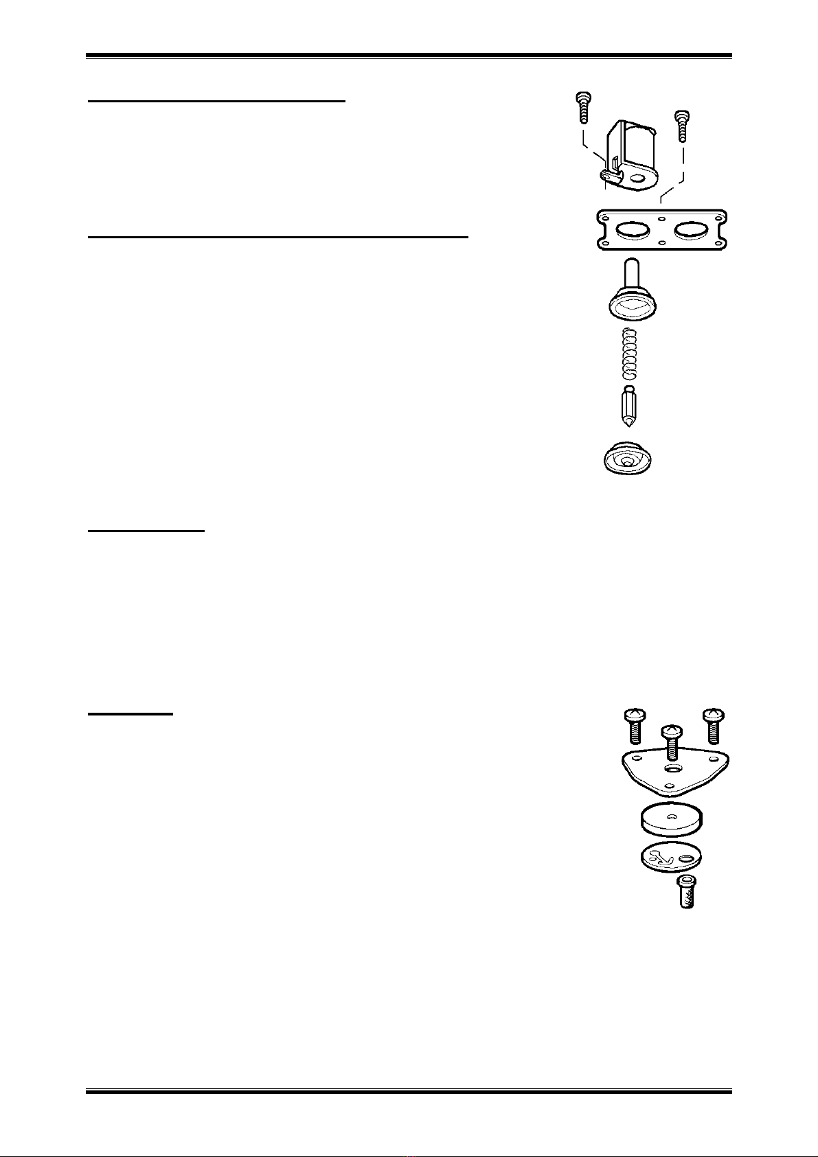
Backwash/refill solenoid
1. Disconnect the connector from the solenoid.
2. Remove the screw holding the solenoid in place and lift away the solenoid.
3. Reverse the procedure for reassembly.
Backwash/refill solenoid diaphragm
1. Disconnect the connector from the solenoid(s).
2. Remove the screw(s) holding the solenoid(s) in place and lift away the
solenoid(s).
3. Remove the remaining screws holding down the retainer.
4. Place a hand under the retainer and remove the retainer; the guide(s), the
solenoid plunger(s) and the plunger spring(s) will fall into your hand.
5. Verify that the solenoid plunger moves smoothly against the plunger spring
inside of the guide; clean or replace if necessary.
6. Separate the solenoid diaphragm(s) from the valve body.
7. Clean out the diaphragm cavity in the valve body.
8. Check the diaphragm for rips or tears; the diaphragm should have 1 hole in the
centre and 2 smaller holes off centre.
9. Reverse the procedure for reassembly.
Valve head
1. Disconnect all connectors from the solenoid(s), flow meter and transformer.
2. Loosen the 2 timer housing screws and remove the timer housing from the bracket.
3. Remove the drain hose from the drain solenoid.
4. Remove the 4 valve head screws and pull away the valve head assembly.
5. Reverse the procedure for reassembly; make sure the drain port O-ring is securely installed in the valve body
groove.
Injector
1. Remove the 3 screws holding the injector cover plate in place.
2. Lift off the injector cover plate.
3. Remove the injector and injector gasket.
4. Remove the injector filter and check for dirt or clogging.
5. Install the injector filter.
6. Install a new injector gasket; mind the alignment over the alignment post.
7. Install the injector; mind the alignment over the alignment post.
8. Install the injector cover plate.
9. Install the 3 injector cover plate screws and tighten them evenly.

541N SERIES
Erie Water Treatment Controls – Belgium
Page 18
Brine draw restrictor
For injectors 8 and 9, an additional 'restrictor' is used that is located in:
541N18/N19: the brine elbow.
541N94/N99: the back cap.
The restrictor is tightly pressed in, to ensure a leakage free seal. Do NOT remove the restrictor to prevent damage
of restrictor and/or seal.
To access the restrictor for cleaning purposes:
541N18/N19
1. Remove the brine line from the brine elbow.
2. Remove the clip that secures the brine elbow.
3. Check restrictor for dirt or clogging; clean if necessary by blowing air through restrictor.
4. Install the brine elbow and secure it with the clip.
5. Install the brine line to the brine elbow.
541N94/N99:
1. Remove the brine line from the brine elbow.
2. Disconnect the connector from the backwash/refill solenoid.
3. Remove the 4 screws from the back cap.
4. Place a hand under the back cap and remove the back cap; the check disk spring and
check ball might fall into your hand.
5. Check restrictor for dirt or clogging; clean if necessary by blowing air through
restrictor.
6. Install the check disc on the body stem assembly and the check disc spring onto the
centre post of the check disc.
7. Install the check ball in the refill cavity of the valve body.
8. Make sure the back cap gasket is securely installed in the back cap grooves.
9. Align the mark on top of the back cap with the mark on the valve body and install
the back cap with the open end of the check disk spring onto the centre post of the
back cap.
10. Install the 4 screws and tighten them.
11. Install the connector to the backwash/refill solenoid.
12. Install the brine line to the brine elbow.
Incorporated drain flow control (optional)
1. Remove the valve head; refer to Parts Replacement “Valve head”.
2. Locate the drain flow control in the drain channel of the valve head.
3. Pull out the drain flow control.
4. Reverse the procedure for reassembly; make sure the drain port O-ring is securely installed in the valve body
groove.
Main diaphragm
1. Remove the valve head; refer to Parts Replacement “Valve head”.
2. Remove the screw and washer from the centre of the main diaphragm.
3. Remove the main diaphragm from the body stem assembly.
4. Reverse the procedure for reassembly; make sure the drain port O-ring is securely installed in the valve body
groove.
This manual suits for next models
4
Table of contents
Other Erie Control Unit manuals


