6
CONTROL UNIT MOUNTING
The Metalarm 3500 control unit is supplied with four
mounting brackets for wall mounting. The dimensions
are shown in Figure 1.
Ideally the control unit should be mounted within 10-15'
(3-5 m) of the sensor coil unit and no more than
66' (20 m).
The control unit must be mounted in a location with
low amounts of vibration, if the area exhibits a high
level of vibration, independent mounting of the control
enclosure must be implemented. Shock mounts for the
control enclosure may be another consideration, based
on the severity of the installation.
The Metalarm 3500 control unit will normally be
mounted by means of four 5/16 inch or M8 bolts
utilizing the four mounting holes.
Adequate clearance must be allowed below the control
unit enclosure to allow for cable entry and exit.
NOTE: Do not replace the HDPE mounting bars, as
these are provided to electrically isolate the control
unit from the metal conveyor framework. Similarly no
metal work should be in contact with the metal control
unit case after mounting on the conveyor.
Failure to comply with the above mounting procedures
will invalidate the ‘CE’ certificate covering the
EMC regulations.
SEARCH COIL MOUNTING
The following instructions give details of how to install
the various types of standard search coils supplied as
part of the Metalarm Metal Detector.
The search coil should be assembled using the
instructions supplied with the search coil.
UNDERBELT COIL (MODEL TR) ‑
IDLER CONVEYORS
Locate a suitable position in the conveyor mid way
between two idlers where:
• There will not be a return idler or cross piece
beneath the search coil.
• There is not a joint in the conveyor frame.
Installation • Metal, when detected, can easily be removed from
the conveyor belt.
• There is no moving metal in the vicinity.
• Any metal base plate present can be removed or
replaced by non-metallic material.
• Any metal covers over the belt can be removed or
replaced by non-metallic material.
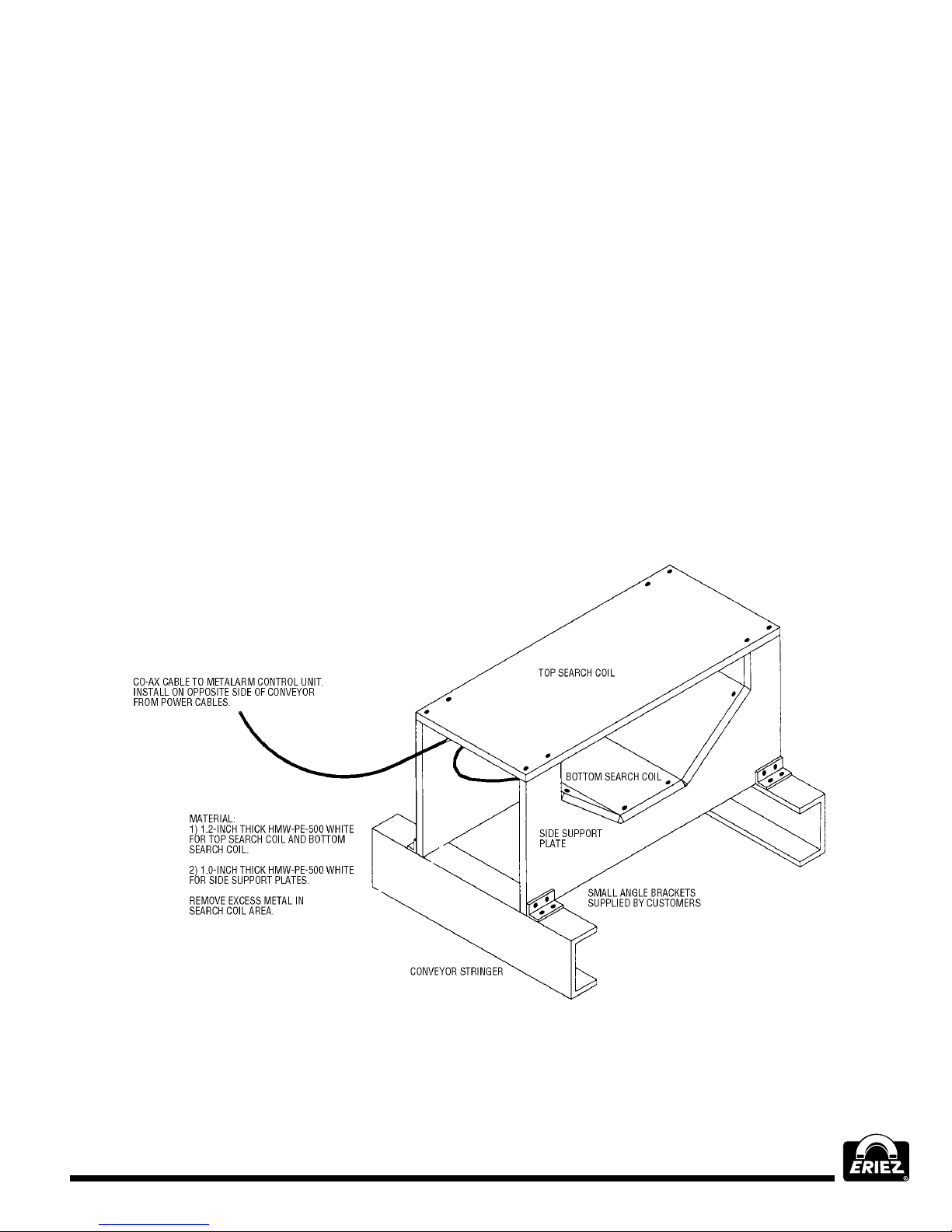
Place the search coil on the conveyor frame at the
chosen position. There should be at least a 1' (25mm)
gap between the underside of the conveyor belt and
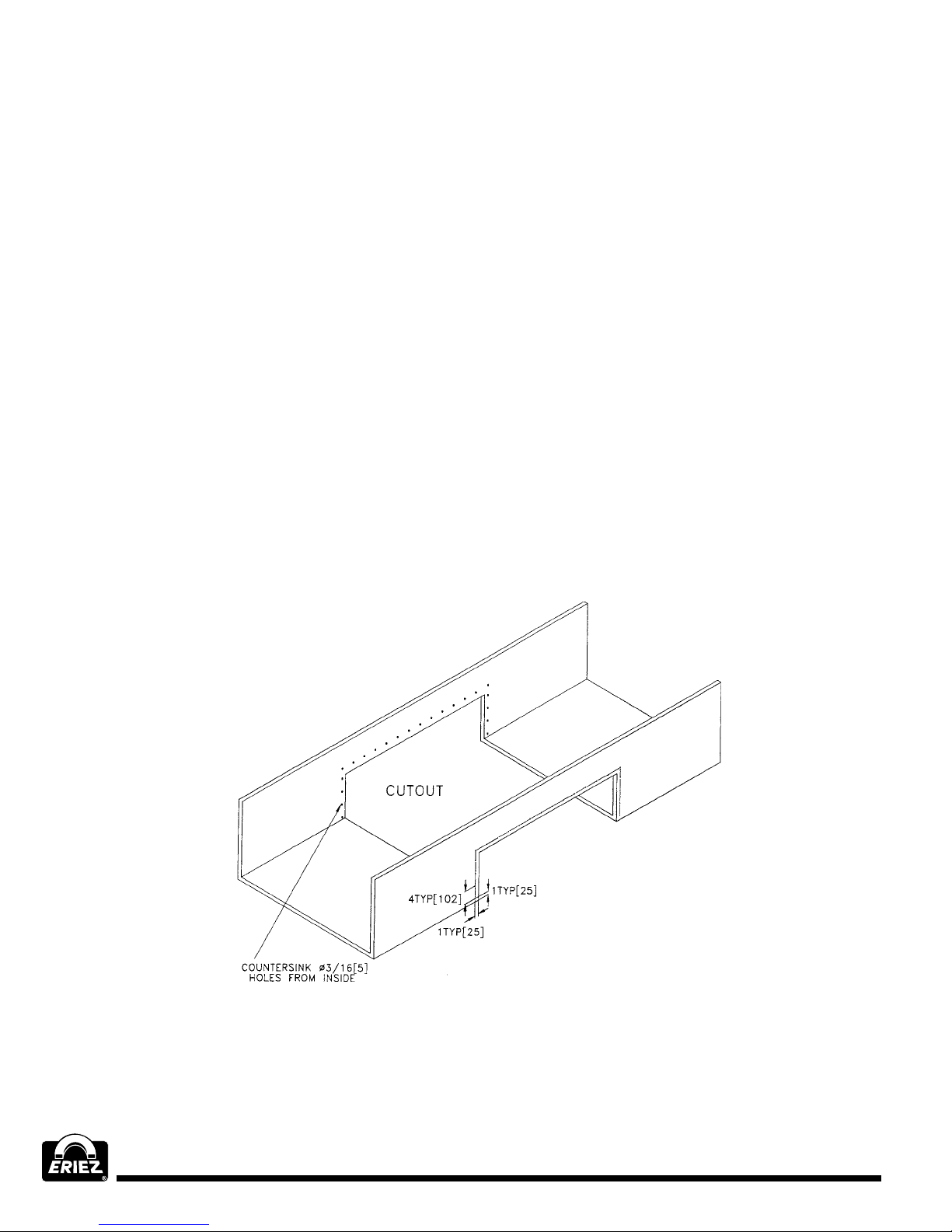
the top of the search coil. If not cut out notches in the
bottom of the search coil at all four corners so as to
lower the search coil within the conveyor frame.
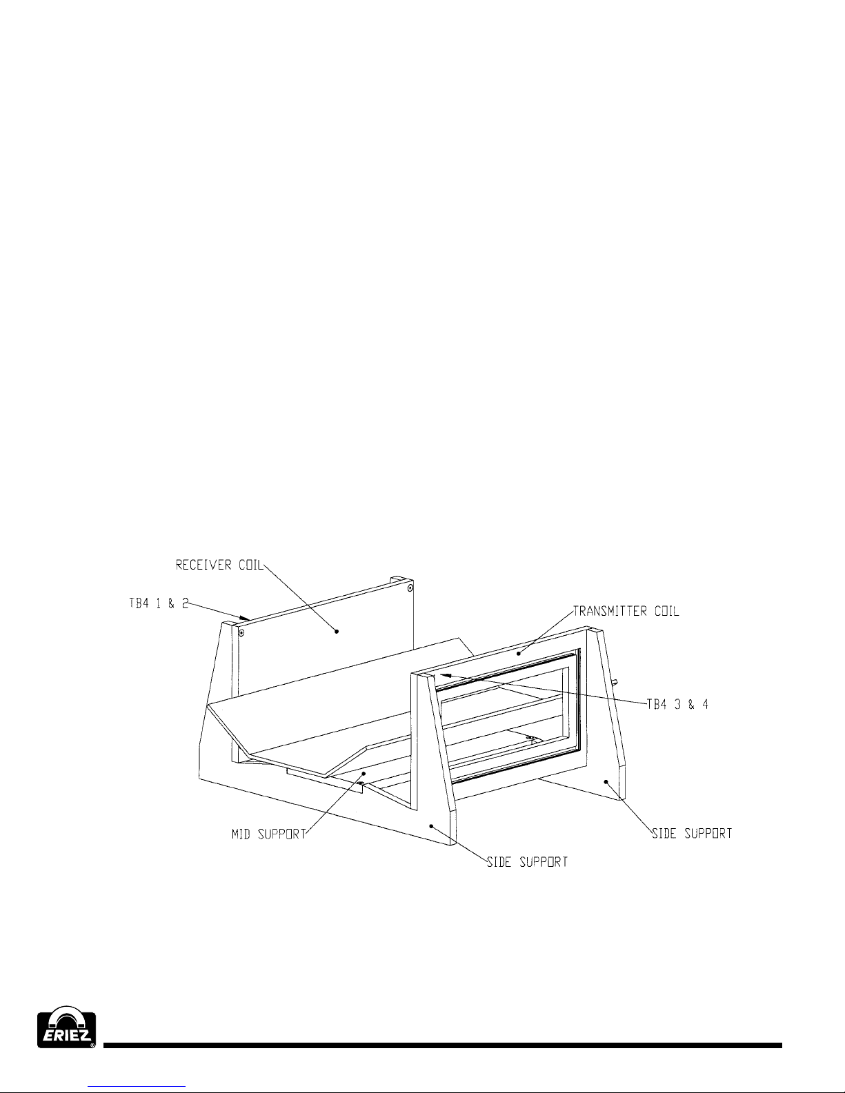
User supplied stainless steel “L” brackets are
suggested for securing the search coil assembly to the
conveyor. Brackets should be fitted to the coil, in the
area marked for such purposes, as shown on the coil
assembly drawing. (See Figure 2)
The search coil should then be bolted to the conveyor
frame with the coil electrical connection on the
opposite side of the conveyor frame to any heavy-duty
cables or wiring.
A recommended idler spacing of 48"- 60" should apply
to the infeed and outfeed idlers adjacent to the search
coil. An idler isolation kit is recommended and may
be purchased from the factory. The idler isolation kit
provides suitable materials to electrically insulate the
idlers from the conveyor frame. Insulating the idlers
directly adjacent to each side of the search coil will help
to alleviate any possible false tripping. Electrical loops
can be created from the metal detectors field in relation
to the surrounding metal. The idlers on each side of
the search coil should be checked to see that all nuts
and bolts have been securely tightened.
The cable connecting the search coil to the control
unit should then be attached to the connector on the
underside of the search coil and to the control unit. The
cable should be secured and protected from damage.