ero electronic PKC User manual

rUSER MANUAL PKC
MKC
170.IU0.XKC.0C1 05-02
Xkc-01-C0.P65 5/29/02, 11:58 AM1

Xkc-01-C0.P65 5/29/02, 11:58 AM2

INDEX
MOUNTING REQUIREMENTS ................................................. 1
OUTLINE AND CUT OUT DIMENSIONS ................................. 2
CONNECTION DIAGRAMS ...................................................... 4
PRELIMINARY HARDWARE SETTINGS ............................... 17
SECURITY CODE SETTING MODE ...................................... 22
RUN TIME AND CONFIGURATION MODE ........................... 25
General notes about graphic symbols .............................. 25
Keyboard description ....................................................... 25
CONFIGURATION MODE ...................................................... 27
RUN TIME MODE ................................................................... 62
Display function ................................................................ 62
Indicators ......................................................................... 64
Bargraph description ........................................................ 65
OUT failure detection function (OFD) .............................. 66
Direct access to the set point ........................................... 66
Manual function ................................................................ 67
Serial link ......................................................................... 68
Lamp test ......................................................................... 69
SMART function ............................................................... 69
Hold function .................................................................... 70
Parameter protection ....................................................... 70
RUN TIME PARAMETER MODIFICATION ............................ 71
ERROR MESSAGES .............................................................. 97
GENERAL INFORMATIONS ................................................ 103
MAINTENANCE .................................................................... 112
DEFAULT PARAMETERS .................................................... A.1
ALPHANUMERIC INDEX OF THE
DISPLAY INDICATION ......................................................... B.1
CODING ................................................................................ B.7
Xkc-01-C0.P65 5/29/02, 11:58 AM3

Xkc-01-C0.P65 5/29/02, 11:58 AM4

1
MOUNTING REQUIREMENTS
Select a location, for instrument mounting, where
minimum vibrations are present and the ambient
temperature is within 0 and 50 °C (32 and
122 °F).
The instrument can be mounted on a panel up to
15 mm thick with a cutout of 92 x 45 mm (PKC) or
92 x 92 (MKC).
For outline and cutout dimensions refer to Fig. 2.
The surface texture of the panel must be better
than 6,3 mmm.
The instrument is shipped with rubber panel
gasket (50 to 60 Sh).
To assure the IP65 and NEMA 4 protection, insert
the panel gasket between the instrument and the
panel as shown in fig. 1.
While holding the instrument against the panel
proceed as follows:
1) insert the gasket in the instrument case;
2) insert the instrument in the panel cutout;
3) pushing the instrument against the panel;
4) insert the mounting brackets as shown in fig.1;
5) with a screwdriver, turn the screws with a
torque between 0.3 and 0.4 Nm. Fig. 1
Gasket
bracket
bracket Panel
Screws
Screw
Panel
Screw
brackets
Gasket
Xkc-1-C0.P65 5/29/02, 11:59 AM1

2
OUTLINE AND CUT OUT
DIMENSIONS
Fig. 2.A OUTLINE AND CUT-OUT DIMENSIONS FOR PKC MODEL
Xkc-1-C0.P65 5/29/02, 11:59 AM2

3
Fig. 2.B OUTLINE AND CUT-OUT DIMENSIONS FOR MKC MODEL
Xkc-1-C0.P65 5/29/02, 11:59 AM3
4
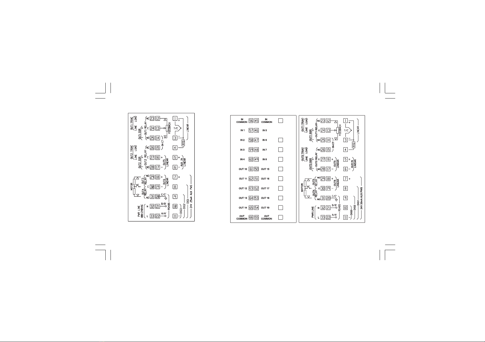
CONNECTION DIAGRAMS
Fig. 3.A PKC -REAR TERMINAL BLOCK Fig. 3.B MKC REAR TERMINAL BLOCK
Xkc-1-C0.P65 5/29/02, 11:59 AM4

5
Connections are to be made with the instrument housing
installed in its proper location.
A) MEASURING INPUTS
NOTE: Any external component (like zener barriers etc.)
connected between sensor and input terminals may cause
errors in measurement due to excessive and/or not balanced
line resistance or possible leakage currents.
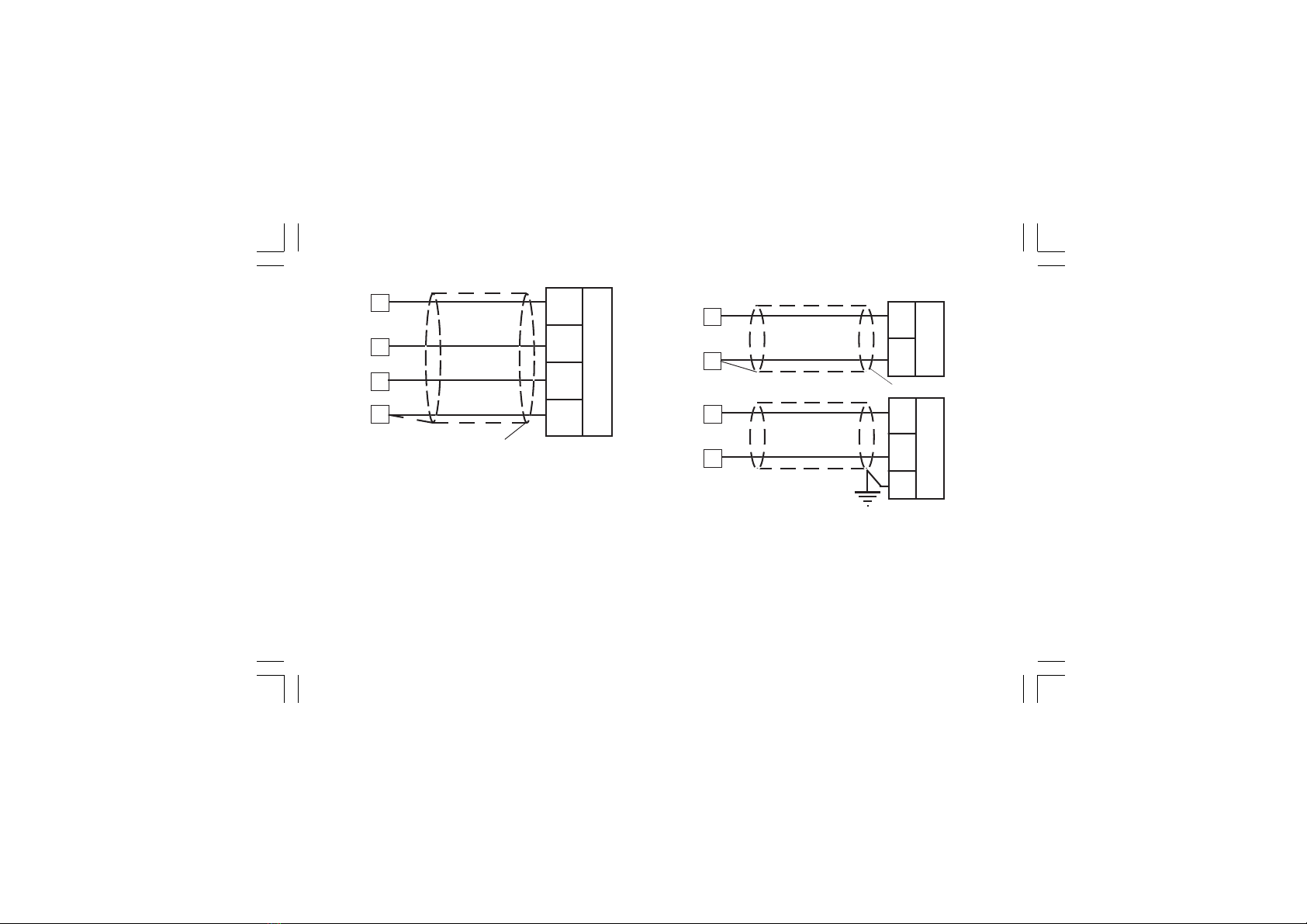
A.1) TC INPUT
Fig. 4 THERMOCOUPLE INPUT WIRING
NOTES:
1) Don’t run input wires together with power cables.
2) For TC wiring use proper compensating cable preferable
shielded.
3) When a shielded cable is used, it should be connected at
one point only.
3
+
_
Shield
1
3
+
_
Shield
1
Xkc-1-C0.P65 5/29/02, 11:59 AM5

6
A.3) LINEAR INPUT
Fig. 6 mA, mV AND V INPUTS WIRING
NOTES:
1) Don’t run input wires together with power cables.
2) Pay attention to the line resistance; a high line resistance may
cause measurement errors.
Shield
_
+mA,
mV
or
V
3
1
+
_
G
mA
mV
or
V
1
3
4
RTD
13 4
RTD
13
A.2) RTD INPUT
Fig. 5 RTD INPUT WIRING
NOTES:
1) Don’t run input wires together with power cables.
2) Pay attention to the line resistance; a high line resistance may
cause measurement errors.
3) When shielded cable is used, it should be grounded at one
side only to avoid ground loop currents.
4) The resistance of the 3 wires must be the same.
Xkc-1-C0.P65 5/29/02, 11:59 AM6

7
Shield
+
_
TX
3
1
11
7
3) When shielded cable is used, it should be grounded at one
side only to avoid ground loop currents.
4) The input impedance is equal to:
< 5 Wfor 20 mA input
> 1 MWfor 60 mV input
> 200 kWfor 5 V input
> 400 kWfor 10 V input
A.4) 2, 3 AND 4-WIRE TRANSMITTER INPUT
Fig. 7.A INPUTS WIRING FOR 2-WIRE TRANSMITTER
Fig. 7.B INPUTS WIRING FOR 3-WIRE TRANSMITTER
Shield
3
1
11
7
PWR
+
Out
TX
GND
Xkc-1-C0.P65 5/29/02, 11:59 AM7
8
B) AUXILIARY INPUT
Fig. 8 AUXILIARY INPUT WIRING
NOTES:
1) This input is not isolated from measuring input. A double or
reinforced insulation between instrument output and power
supply must be assured by the external instrument.
2) Don’t run input wires together with power cables.
3) Pay attention to the line resistance; a high line resistance may
cause measurement errors.
Shield
_
+mA
or
V
6
5
+
_
G
mA
or
V
5
6
Fig. 7.C INPUTS WIRING FOR 4-WIRE TRANSMITTER
NOTES:
1) Don’t run input wires together with power cables.
2) Pay attention to the line resistance; a high line resistance may
cause measurement errors.
3) When shielded cable is used, it should be grounded at one
side only to avoid ground loop currents.
4) The input impedance is lower than 5 W(20 mA input)
Shield
3
1
11
7PWR
+
Out
+
TX
PWR
_
Out
_
Xkc-1-C0.P65 5/29/02, 11:59 AM8

9
8
9
10
11
DIG. 1
DIG. 2
DIG. 3
4) When shielded cable is used, it should be grounded at one
side only to avoid ground loop currents.
5) The input impedance is equal to:
< 5 Wfor 20 mA input
> 200 kWfor 5 V input
> 400 kWfor 10 V input
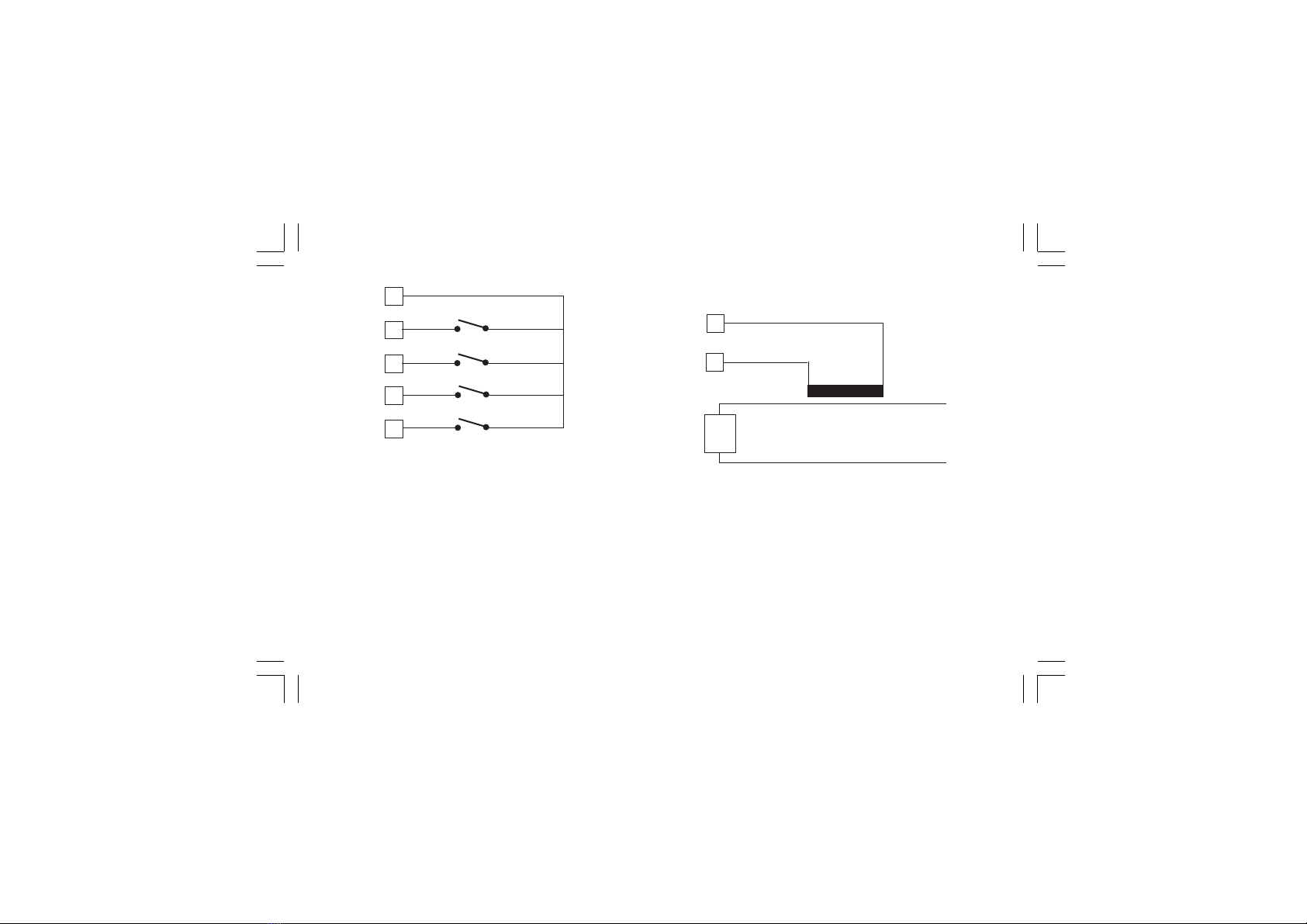
C) LOGIC INPUT
Fig. 9.A - LOGIC INPUTS DIG.1, 2 and 3 WIRING
Fig. 9.B - LOGIC INPUTS IN 1, 2, 3 and 4 WIRING
58
59
IN 2
IN 3
56
57
IN 1
60
IN 4
Xkc-1-C0.P65 5/29/02, 11:59 AM9
10
14
15
Load
Current
transformer
D) CURRENT TRANSFORMER INPUT
Fig. 10 CURRENT TRANSFORMER INPUT WIRING
This input allows you to measure and display the current running
in the load, driven by a time proportional control output, during
the ON and OFF periods of the output cycle time. By this feature
it is also available the "Output failure detection" function (see
page 66).
Fig. 9.c - LOGIC INPUTS IN 5, 6, 7 and 8 WIRING
NOTES:
1) Do not run logic input wiring together with power cables.
2) Use an external dry contact capable of switching 0.5 mA,
5 V DC.
3) The instrument needs 110 ms to recognize a contact status
variation.
4) The logic inputs are NOT isolated by the measuring input. A
double or reinforced insulation between instrument output and
power supply must be assured by the external element.
47
48
IN 6
IN 7
45
46
IN 5
49
IN 8
Xkc-1-C0.P65 5/29/02, 11:59 AM10

11
NOTES:
1) This input is not isolated from measuring input. A double or
reinforced insulation between instrument output and power
supply must be assured by the external element.
2) Do not run current transformer input wiring together with AC
power cables.
3) The minimum active period to perform this measurement is
equal to 120 ms.
4) The input impedance is equal to 20 W.
E.1) RELAY OUTPUTS
Fig. 11.A RELAY OUTPUTS 1,2,3 and 4 WIRING
OUT 1
23 NC
24 C
25 NO
OUT 2 27 C
NO
28
OUT 3
29 NO - OUT 3
OUT 4
30 C - OUT 3/4
31 NO - OUT 4
26 NC
Xkc-1-C0.P65 5/29/02, 11:59 AM11

12
OUT 10 61 NO OUT 10
62 NO OUT 11
NO OUT 12
63
64 NO OUT 13
65 NO OUT 14
66 COMMON
OUT 11
OUT 12
OUT 13
OUT 14
COMMON
OUT 15 50 NO OUT 15
51 NO OUT 16
NO OUT 17
52
53 NO OUT 18
54 NO OUT 19
55 COMMON
OUT 16
OUT 17
OUT 18
OUT 19
COMMON
The outputs from OUT 1 to OUT 4 are equipped with relays
having contact rating equal to 3A/250V AC on resistive load.
WARNING: When OUT 3 and 4 are used as independent relay
outputs the addition of the two currents must not exceed 3 A.
Fig. 11.B RELAY OUTPUTS 10 to 14 WIRING
Fig. 11.C RELAY OUTPUTS 15 to 19 WIRING
The outputs from OUT 10 to 19 are equipped with relays having
contact rating equal to 0.5A/250V AC on resistive load.
Xkc-1-C0.P65 5/29/02, 11:59 AM12

13
Fig. 12 EXTERNAL SWITCH IN SERIES WITH THE INTER-
NAL CONTACT
In this case it is recommended to install an additional RC
network across the external contact as show in Fig. 12
The value of capacitor (C) and resistor (R) are shown in the
following table.
Anyway the cable involved in relay output wiring must be as far
away as possible from input or communication cables.
NOTES 1) To avoid electrical shock, connect power line at
the end of the wiring procedure.
2) For power connections use No 16 AWG or larger
wires rated for at last 75 °C.
3) Use copper conductors only.
4) Don’t run input wires together with power cables.
All relay contacts are protected by varistor against inductive load
with inductive component up to 0.5 A.
The following recommendations avoid serious problems which
may occur, when using relay output for driving inductive loads.
INDUCTIVE LOADS
High voltage transients may occur switching inductive loads.
Through the internal contacts these transients may introduce
disturbances which can affect the performance of the instru-
ment.
For all the outputs, the internal protection (varistor) assures a
correct protection up to 0.5 A of inductive component.
The same problem may occur when a switch is used in series
with the internal contacts as shown in Fig. 12.
R
C
LOAD
LINE
LOAD
(mA)
<40 mA
<150 mA
<0.5 A
C
(mF)
0.047
0.1
0.33
R
(W)
100
22
47
P.
(W)
1/2
2
2
OPERATING
VOLTAGE
260 V AC
260 V AC
260 V AC
Xkc-1-C0.P65 5/29/02, 11:59 AM13

14
NOTE: This output is not isolated.
A double or reinforced insulation between instrument output and
power supply must be assured by the external solid state relay.
E.3) TRIAC OUTPUTS
Fig. 14 TRIAC OUTPUT WIRING
23 Load
24 Line
26 Load
27 Line
OUT 1
OUT 2
E.2) VOLTAGE OUTPUTS FOR SSR DRIVE
Fig. 13 SSR DRIVE OUTPUT WIRING
Logic level 0: Vout < 0.5 V DC.
Logic level 1:
- 14 V + 20 % @ 20 mA
- 24 V + 20 % @ 1 mA.
Maximum current = 20 mA.
+
__
+
24
25
OUT 1
SOLID STATE
RELAY
+
__
+
27
28
OUT 2
SOLID STATE
RELAY
Xkc-1-C0.P65 5/29/02, 11:59 AM14

15
E.4) SERVOMOTOR OUTPUT
Fig. 15 SERVOMOTOR OUTPUT WIRING
Switching mode: isolated zero crossing type.
Rated current: from 50 mA to 1 A.
Rated voltage: from 24 VRMS to 240 VRMS -10 % +15 % (50/
60Hz)
Load type: resistive load only
NOTES 1) To avoid electrical shock, connect power line at
the end of the wiring procedure.
2) For power connections use No 16 AWG or larger
wires rated for at last 75 °C.
3) Use copper conductors only.
4) Don’t run input wires together with power cables.
5) This output is not fuse protected. Please, provide it
externally using a fuse with a I2t equal to128.
29
30
31
Servo-
motor
Power
line
12
13
14
s(Open the valve)
t(Close the valve)
Feedback
potentiometer
Shield
s(Open)
t(Close)
Xkc-1-C0.P65 5/29/02, 11:59 AM15

16
The two relay output must be interlocked (see chapter
"Preliminary hardware setting" paragraph "Out 3 and 4
selection").
NOTES:
1) Before connecting the instrument to the power line, make sure
that line voltage and the load current are in accordance with the
contact rating (3A/250V AC on resistive load).
2) To avoid electric shock, connect power line at the end of the
wiring procedure.
3) For servomotor connections use No 16 AWG or larger wires
rated for at last 75 °C.
4) Use copper conductors only.
5) Don’t run input wires together with power cables.
6) For feedback potentiometer, use shielded cable with the shield
connected to the earth at one point only.
7) The relay outputs are protected by varistor against inductive
load with inductive component up to 0.5 A.
E.5) ANALOG OUTPUTS
Fig. 16.A OUTPUT 5 WIRING
+
_
Shield
_
+
17
+
_
G
16
17
16
OUT 5
OUT 5
20 mA20 mA
+
_
Xkc-1-C0.P65 5/29/02, 11:59 AM16
This manual suits for next models
1
Table of contents
Other ero electronic Controllers manuals


Popular Controllers manuals by other brands

AUMA
AUMA SA 25.1 operating instructions

Nordson EFD
Nordson EFD ValveMate 7197PCP operating manual

ActronAir
ActronAir QTW-1000 Installation and commissioning manual

Vaillant
Vaillant sensoCOMFORT VRC 720 Operating and installation instructions

Zennio
Zennio MAXinBOX SHUTTER 8CH v3 Technical documentation

opto engineering
opto engineering LTDVE8CH-20 instruction manual


