Erone EACP105E User manual

ELECTRONIC CONTROL PANEL FOR TWO 230Vac
MOTORS
APPARECCHIATURA DI COMANDO 2 MOTORI 230Vac
ARMOIRE DE COMMANDE 2 MOTEURS 230 Vac
ENGLISH
EN
EACP105E
Installation manual / Manuale di installazione/
Manuel d’installation
ITALIANO
IT
FRANÇAIS
FR

GALEO
Illuminated RF Keypad
INSTALLATION MANUEL
EACP105E
Electronic control panel for two 230Vac motors
INSTALLATION MANUAL EN
2erone.com
1] Product range
Important precautIons for the safety
The present document contains important precautions for the use and the operating safety.
Read carefully the instructions before commencing the installation. Keep this document even
after installation.
!
This product, if properly installed by specialized personnel, able to perform the necessary risk
analysis, complies with the Regulations EN 12453 - EN 12445
These warnings are integral and essential parts of the product and must be delivered to the user. Read them
carefully as they provide important information regarding installation, use and maintenance. This form must be
kept and transmit it to any subsequent users in the use of the system. Incorrect installation or use improper use
of the product can be a source of serious danger.
2] Dimensions
Part-name Part-Number Description
EACP105E F0544000047 2 MOTORS 230Vac control panel w/enclosure
EACP105 F0544000046 2 MOTORS 230Vac control panel card
319
223
100
285.4
195.4
Fig.1

3erone.com
GALEO
Illuminated RF Keypad
INSTALLATION MANUEL
EACP105E
Electronic control panel for two 230Vac motors
INSTALLATION MANUAL EN
4] Technical specications
Parameter Value
Power supply 230 Vac +/- 10% / 50 Hz
Max motor power 550 W
Power for accessories 12/24 Vac - 250 mA
Automatic reclosing time 5 - 120 Sec.
Working time 3 - 120 Sec.
Courtesy light time 180 Sec.
Memory for S/N security codes 260
Security protocol Keeloq Hopping code
Frequency 433,92 MHz
Operating temperature -20 / +70°C
Enclosure protection IP55
1) Depending on the type of the gates, locate the best position for the appliance, close to the gate, safe from
shocks and tampering, high enough from the ground, safe from water and easily accessible for maintenance
operations.
2) Unscrew the 4 screws of the cover and verify the electronic card integrity. (Fig. 2).
3) Trace the 4 xing points using the container as template mark or making reference to the distances shown on
Fig. 1
4) Drill 4 holes Ø6 mm for the plugs and fasten the box with 4 x M4 screws.
5) Insert the cable holders ( if provided ) throught the pre-cuted holes and pass the cables, keeping the mains
cables and low voltage cables seperated .
6) If not provided with the appliance, connect an all-pole 10A thermal breaker switch with contact opening distance
of 3 mm or greater.
Make sure that a differential switch with threshold of 0.03 A is tted upstream of the system.
7) Make the connections with reference to paragraph 7.
3] Installing

GALEO
Illuminated RF Keypad
INSTALLATION MANUEL
EACP105E
Electronic control panel for two 230Vac motors
INSTALLATION MANUAL EN
4erone.com
5] Preliminary recommendations
• Installation and testing must be carried out only by qualied personnel to guarantee the
correct and safe functionality of the automatic gate.
• The manufacturer declines all responsibility for damages deriving from any incorrect
installation due to incapacity and / or negligence.
• Before proceeding with the installation of the automatiion, check that the door is fully
functional and balanced.
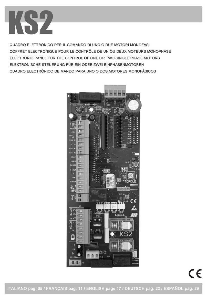
6] Main board layout
1 2 3 4 5 6 7 8 9 10 11
T1 T2 T3
25 26 27 28 29
12 13 14 15 16 17 18 19 20 21 22 23 24
30 31
P2
PG2 PG1
FUSE 1A
FUSE 6A
FUSE 6A
Buzzer
P3
LV
LR
JP1

GALEO
Illuminated RF Keypad
INSTALLATION MANUEL
EACP105E
Electronic control panel for two 230Vac motors
INSTALLATION MANUAL EN
5
erone.com
7] Connections
POWER SUPPLY & MOTOR CONNECTIONS
TERMINAL CONNECTIONS
1 2 6 7 8 9 1011
LN
230 V~
M1 M2
3 5 21222324
3 4
Flashing
Lamp
230 V~
Courtesy
Light
230 V~
151617
FTC OP
FTC CH
121314
FCC2
FCA2
181920
FCC1
FCA1
PED.
STOP
START
POWER SUPPLY ACCESSORIES / ELECTROLOCK / ANTENNA
25 27
24 V~
26 27
12 V~
28 29
12 V=
+ -
Electrolock
30 31
RG58
Antenna
POTENTIOMETERS
+
-+
-+
-
T1 T2 T3
T1 adjusts torque and
sensitivity in regular mode
T2 adjusts torque and sensitivity
in slow down mode T3 adjusts the pause
time [3 - 120 sec.]

GALEO
Illuminated RF Keypad
INSTALLATION MANUEL
EACP105E
Electronic control panel for two 230Vac motors
INSTALLATION MANUAL EN
6erone.com
Terminals Type Description
1 - 2 230 V~ Input Line L-N
3 - 4 230 V~ Output ashing lamp
3 - 5 230 V~ Output courtesy light
6 - 7 - 8 230 V~ Input MOTOR 1 : 6,7 Opening / Closing - 8 Common
9 - 10 - 11 230 V~ Input MOTOR 2 : 9,10 Opening / Closing - 11 Common
12 - 14 NC Open limit switch Motor 2 (*)
13 - 14 NC Close limit switch Motor 2 (*)
15 - 17 NC Contact safety Bar ( reopen photocell ) (*)
16 - 17 NC Contact Close photocell (*)
19 - 18 NC Close limit switch Motor 1 (*)
20 - 18 NC Open limit switch Motor 1 (*)
21 - 23 NC STOP Command (*)
22 - 23 NO Pedestrian Open
24 - 23 NO START Command ( open / stop / close / stop )
25 - 27 24 V~ Power supply photocells + accessories 24 V~ / 250 mA
26 - 27 12 V~ Power supply photocells + accessories 12 V~ / 250 mA
28 - 29 12 V= Power supply Electrolock
30 - 31 50 Ohm Input antenna - Cable RG58 ( 30 GND, 31 SIGNAL)
(*) : short if not used
8] Legenda connections

GALEO
Illuminated RF Keypad
INSTALLATION MANUEL
EACP105E
Electronic control panel for two 230Vac motors
INSTALLATION MANUAL EN
erone.com 7
N° Function Dip-switch Pos Description
1Automatic
closing
ON Automatic closing activated
OFF Automatic closing disabled
2Condominium /
step-by-step
ON During opening does not accept further commands
OFF Command : OPEN/STOP/CLOSE/STOP
3Not used
ON Not used
OFF Not used
4Opening Jolt
ON Opening jolt enabled
OFF Opening jolt disabled
5Contact safety
in opening
ON NC contacts (15-17), stop & invert for 2 sec on opening, stop & invert
the direction on closing
OFF NC contacts (15-17) stop the movement on opening, stops & inverts
on closing
6Flashing
function
ON Warning light blinking
OFF Warning light xed
7Slow down
ON slow down mode at the end of each manouvre ( opening and closing )
OFF No slow down : full torque
8
Periodic closing
command for
security
ON Every 180 min, the panel gives a closing command, avoiding any
gate-opened situation
OFF Function disabled
9] Dip-switch settings
NOTES
• Safety edge, connected on terminals 15-17 - This contact protects opening and closing.
DIP 5 ON: When there is an obstacle, the motors stop and reverse for 2 sec.
DIP 5 OFF: When there is an obstacle motors STOP.
In both cases after the disengagement resumes the opening.
• Photocells, connected on terminals 16-17 - This contact protects only in closing : when there is an
obstacle the motors STOP;
• Emergency Stop connected on terminals 21-23 - The contact, if open, will cause the immediate stop of
the automation in any situation.
FLASHING LIGHT
If Dip6=ON then: IN OPENING: blinking slow
IN CLOSING: blinking fast
IN PAUSE: steady light
PHOTOCELL ENGAGED: Turn off

GALEO
Illuminated RF Keypad
INSTALLATION MANUEL
EACP105E
Electronic control panel for two 230Vac motors
INSTALLATION MANUAL EN
8erone.com
10a] Double gates programming
The programming starts with the gate closed. The rst operation must be the opening: if the gates close, invert
the connection of the motor wires on the terminals.The programming of the gates will be done using the buttons
PG1 for gate 1 and PG2 for gate 2.To enter the programming press P2 for 2 sec LED L3 lights up.
PG1
PG2
P2
2 sec.
L3
Wait for leaves
staggering
Press PG2 :
gate 2 starts
Press PG1 :
gate 1 starts
1 - OPENING PROGRAMMING
PG1
Press PG1 : gate 1 starts
the slow down (*)
PG2
Press PG2 : gate 2 starts
the slow down (*)
PG1
Press PG1 :
gate 1 stops
PG2
Press PG2 :
gate 2 stops
Press PG2 :
gate 2 starts
closing
Wait for leaves
staggering
Press PG1 :
gate 1 starts
closing
PG2
Press PG2 : gate 2
starts the slow down
(*)
PG1
Press PG1 : gate 1
starts the slow down
(*)
Press PG2 :
gate 2 stops
PG2
PG1
Press PG1 :
gate 1 stops
2 - CLOSING PROGRAMMING
End of the procedure

GALEO
Illuminated RF Keypad
INSTALLATION MANUEL
EACP105E
Electronic control panel for two 230Vac motors
INSTALLATION MANUAL EN
10b] Single gate programming
PG1
P2
2 sec.
L3
Press PG1 :
gate starts
1 - OPENING PROGRAMMING
PG1
Press PG1 : gate
starts the slow down
(*)
PG1
Press PG1 :
gate stops
Press PG1 :
gate starts
closing
PG1
Press PG1 : gate
starts the slow
down (*)
PG1
Press PG1 :
gate stops
2 - CLOSING PROGRAMMING
(*) NOTE : The programming of the panel, without slow down ( dip-switch 7 = OFF ) is similar to the
programming with the slow down, except for the pressure of the buttons PG1 & PG2 next to the limits, that in
this case is missing.
End of the procedure
To enter the programming press P2 for 2 sec LED L3 lights up.
11a] Adding a transmitter using the button P3 of the RX card
P3
LV
P3
LR Press button B
Press
4 Sec. Press
Press button A
Beep
A sequence of 2 pressures of P3 can assign to key A of the transmitter the CH1 of the RX card ( Normal opening
) and to key B the CH2 of the RX card ( Pedestrian opening ).
Beep
Beep Beep
LV x 5sec.
--> OFF
9
erone.com

GALEO
Illuminated RF Keypad
INSTALLATION MANUEL
EACP105E
Electronic control panel for two 230Vac motors
INSTALLATION MANUAL EN
11d]Erasing the full transmitters memory
Release & Press P3
11b] Adding a transmitter without P3
Beep
It is possible to add a new transmitter without accessing to the receiver button P3 but acting on the transmitter
push buttons only. Set the jumper JP1 to enable this function. For this function it is necessary to use a
transmitter already memorized.
Buzzer
P3
LV
LR
JP1
JP1 ON : wireless
memo ENABLED JP1 OFF : wireless
memo DISABLED
Press button A+B
of the OLD TX Release and keep
pressed button A
1. Memorizing Button A on CH1 : Full OPENING
Beeeeeeep
Press button A of the NEW TX
before end of long Beep
Beep
Release and keep
pressed button B
2. Memorizing Button B on CH1 : Pedestrian OPENING
Beep - Beep - Beep
Press button B of the NEW TX
before end of Beep-Beep-Beep
Receiver card
4 sec. LR
P3 P3
Press P3
LV
Blinking
LV
P3 P3
LR
Beep - Beep - Beep
Release & Keep Pressed P3 until
the buzzer makes 3 beeps
P3 P3
Memory
erased!
Release & Press P3
LR
Blinking
Beep
Beep
Press button A+B
of the OLD TX
10 erone.com
11c]Erasing the single transmitter from the memory
Release & Press P3
4 sec. LR
P3 P3
Press P3
LV
Blinking
LV
P3 P3
LR
Release & Press P3
Blinking
Beep - Beep - Beep
Press one button
of the transmitter
Transmitter cancelled!
NOTE: All the buttons
memorized are cancelled LR

GALEO
Illuminated RF Keypad
INSTALLATION MANUEL
EACP105E
Electronic control panel for two 230Vac motors
INSTALLATION MANUAL EN
11
erone.com
• The installation must be performed by professionally competent personnel and in compliance with applicable
local, state, national and European legislation.
• Before starting the installation check the integrity of the product.
• Installation, electrical connections and adjustments must be made a “Rule of art”.
• Packaging materials (cardboard, plastic, polystyrene, etc.) must not be released into the environment and
must not be left within reach of children as potential sources of danger.
• Do not install the product in areas where there is a danger of explosion or high electromagnetic elds. The
presence of ammable gases or fumes is a serious danger for the safety.
• Provide protection against overvoltage on the power supply network, a switch / disconnector and / or
differential suitable for the product and in compliance with the current regulations.
• The manufacturer declines all responsibility if devices are installed and / or incompatible components for the
purposes of product integrity, safety and safety operation.
• Only original spare parts should be used for repairing or replacing defective parts.
• The installer must provide all information regarding operation, maintenance and the use of the individual
components, parts and the whole system.
Read carefully the instructions and the attached documentation.
The product is intended for the used for which it was expressly designed. Every different use mus be considered
improper and therefore dangerous. Furthermore, the information contained in this document and in the attached
documentation, may be subject of changes without notice. They are, in fact, provided as an indication for the
application of the product. The manufacturer declines any and every responsibility. Keep products, devices,
documentation and anything else out of the reach of children.
In case of maintenance, cleaning, breakdown or malfunction of the product, remove power, avoinding any attempt
of intervention. Contact only professional and competent personnel, responsible for the purpose. Failure to
comply with the above warningd can cause situations of serious danger.
15] Warnings for the user
14] Installation recommendations
12] Courtesy light
Terminals 3 - 5 on the main board provide an output 230 Vac / 150W for an external courtesy light.
The courtesy light switches on at the beginning of the motion and ends 180 seconds after the completion of the
closing cycle.
12] Warning light
Phase Funzionamento lampeggiante
Opening Slow blinking
Closing Fast blinking
Pause Light xed
Safety band / Photocells engaged Off

GALEO
Illuminated RF Keypad
INSTALLATION MANUEL
EACP105E
Apparecchiatura di comando 2 Motori 230Vac
MANUALE DI INSTALLAZIONE IT
12 erone.com
ImportantI avvertenze per la sIcurezza
Il presente documento contiene importanti indicazioni per l’utilizzo e la sicurezza di
funzionamento. Leggere attentamente le istruzioni prima di iniziare l’installazione
dell’apparecchiatura. Conservare questo documento anche dopo l’installazione.
Questo prodotto, se installato da personale specializzato idoneo alla valutazione dei rischi,
risponde ai requisiti delle normative EN 12453 - EN 12445.
1] Gamma
!
2] Dimensioni
Part-name Part-Number Descrizione
EACP105E F0544000047 Apparecchiatura di comando per 2 motori 230Vac con box IP55
EACP105 F0544000046 Scheda elettronica di comando per 2 motori 230Vac
319
223
100
285.4
195.4
Fig.1

GALEO
Illuminated RF Keypad
INSTALLATION MANUEL
EACP105E
Apparecchiatura di comando 2 Motori 230Vac
MANUALE DI INSTALLAZIONE IT
13
erone.com
4] Speciche tecniche
Parametro Valore
Alimentazione 230 Vac +/- 10% / 50 Hz
Massima potenza motore 550 W
Potenza alimentazione apparati ausiliari 12/24 Vac - 250 mA
Tempo di richiusura automatica 5 - 120 Sec.
Tempo di lavoro 3 - 120 Sec.
Tempo luce di cortesia 180 Sec.
Memoria trasmettitori 260
Protocollo di sicurezza Keeloq Hopping code
Frequenza RX radio 433,92 MHz
Temperatura di funzionamento -20 / +70°C
Protezione contenitore IP55
1) In base alla tipologia dell’impianto, individuare la posizione migliore dell’apparecchiatura in modo che sia
in prossimità del cancello, al riparo da urti e manomissioni, ad altezza sufciente dal suolo, al riparo da colmi
d’acqua e facilmente raggiungibile dal tecnico per interventi di manutenzione.
2) Aprire il coperchio del contenitore svitando le 4 viti che rimangono prigioniere ed assicurarsi dell’integrità
dell’apparato elettronico (Fig. 2).
3) Tracciare con l’aiuto della scatola i 4 punti di ssaggio o tenendo presenti gli interassi indicati in Fig. 1
4) Praticare i fori Ø6 mm per ssare i tasselli e ssare l’apparecchiatura con 4 viti autolettanti M4.
5) Innestare i passacavi ( se forniti ) attraverso i fori presfondati e far passare i cavi di collegamento tenendo
separati quelli di potenza da quelli di comando.
6) Nel caso non sia fornito con l’apparecchiatura, collegare a monte della linea principale di alimentazione un
interruttore magnetotermico bipolare da 6A con distanza dei contatti di almeno 3 mm.
Vericare inoltre la presenza di un interruttore differenziale da 30 mA a monte del collegamento di linea.
2] Installazione

GALEO
Illuminated RF Keypad
INSTALLATION MANUEL
EACP105E
Apparecchiatura di comando 2 Motori 230Vac
MANUALE DI INSTALLAZIONE IT
14 erone.com
5] Raccomandazioni preliminari
• Le operazioni di installazione e collaudo devono essere eseguite solo da personale qualicato
ai ni di garantire la corretta e sicura funzionalità del cancello automatico.
• La casa costruttrice, declina ogni responsabilità per i danni derivati da eventuali errate
installazioni dovute ad incapacità e/o negligenza.
• Prima di procedere al montaggio dell’automatismo, si verichi che il cancello sia
perfettamente funzionante.
6] Layout scheda elettronica
1 2 3 4 5 6 7 8 9 10 11
T1 T2 T3
25 26 27 28 29
12 13 14 15 16 17 18 19 20 21 22 23 24
30 31
P2
PG2 PG1
FUSE 1A
FUSE 6A
FUSE 6A
Buzzer
P3
LV
LR
JP1

GALEO
Illuminated RF Keypad
INSTALLATION MANUEL
EACP105E
Apparecchiatura di comando 2 Motori 230Vac
MANUALE DI INSTALLAZIONE IT
15
erone.com
7] Collegamenti
ALIMENTAZIONE E COLLEGAMENTO AI MOTORI
CONNESSIONI LAMPEGGIANTE / LUCE DI CORTESIA / SICUREZZE
1 2 6 7 8 9 1011
FN
230 V~
M1 M2
3 5 21222324
3 4
Lampeggiante
230 V~
Luce di
cortesia
230 V~
151617
FTC OP
FTC CH
121314
FCC2
FCA2
181920
FCC1
FCA1
PED.
STOP
START
ALIMENTAZIONE AUSILIARIA / ELETTROSERRATURA / ANTENNA
25 27
24 V~
26 27
12 V~
28 29
12 V=
+ -
Elettroserratura
30 31
RG58
Antenna
TRIMMERS DI REGOLAZIONE
+
-+
-+
-
T1 T2 T3
T1 regola la coppia e la sensibilità
della manovra durante il moto
principale
T2 regola la coppia e la
sensibilità in rallentamento T3 regola il tempo di pausa
[3 - 120 sec.]

GALEO
Illuminated RF Keypad
INSTALLATION MANUEL
EACP105E
Apparecchiatura di comando 2 Motori 230Vac
MANUALE DI INSTALLAZIONE IT
16 erone.com
Morsetti Tipo Descrizione
1 - 2 230 V~ Ingresso alimentazione F-N
3 - 4 230 V~ Uscita lampeggiante
3 - 5 230 V~ Uscita luce di cortesia
6 - 7 - 8 230 V~ Ingresso MOTORE 1 : 6,7 Apertura / Chiusura - 8 Comune
9 - 10 - 11 230 V~ Ingresso MOTORE 2 : 9,10 Apertura / Chiusura - 11 Comune
12 - 14 NC Finecorsa di apertura Motore 2 (*)
13 - 14 NC Finecorsa di chiusura Motore 2 (*)
15 - 17 NC Contatto per Costola di sicurezza ( fotocellula di riapertura ) (*)
16 - 17 NC Contatto fotocellula di chiusura (*)
19 - 18 NC Finecorsa di chiusura Motore 1 (*)
20 - 18 NC Finecorsa di apertura Motore 1 (*)
21 - 23 NC Comando di STOP (*)
22 - 23 NO Apertura PEDONALE
24 - 23 NO Comando di START ( open / stop / close / stop )
25 - 27 24 V~ Alimentazione fotocellule + accessori 24 V~ / 250 mA
26 - 27 12 V~ Alimentazione fotocellule + accessori 12 V~ / 250 mA
28 - 29 12 V= Alimentazione Elettroserratura
30 - 31 50 Ohm Ingresso antenna - Cavo RG58 ( 30 GND, 31 Segnale)
(*) : Ponticellare se non usato
8] Legenda collegamenti

GALEO
Illuminated RF Keypad
INSTALLATION MANUEL
EACP105E
Apparecchiatura di comando 2 Motori 230Vac
MANUALE DI INSTALLAZIONE IT
erone.com 17
N° Funzione Dip-switch Pos Descrizione
1Richiusura
automatica
ON Richiusura automatica attiva
OFF Richiusura automatica disattiva
2Condominiale /
passo-passo
ON In apertura in sistema non accetta ulteriori comandi
OFF Comando sequenziale : APRE/STOP/CHIUDE/STOP
3Non Usato
ON Non usato
OFF Non usato
4Colpo d’ariete
ON Colpo d’ariete attivo
OFF Colpo d’ariete disattivo
5
Contatto di
sicurezza
NC (15-17)
ON In apertura : stop ed inversione del moto per 2 sec.
In chiusura : stop e riapertura.
OFF In apertura : stop
In apertura : stop e riapertura
6Funzionamento
lampeggiante
ON Lampeggio interno
OFF Luce ssa
7Rallentamento
ON Rallentamento attivo alla ne di ciascuna manovra
( apertura e chiusura )
OFF Nessun rallentamento : coppia al 100%
8
Comando
periodico di
chiusura
ON Ogni 180 min la centrale dà un comando di chiusura per
evitare che il cancello resti aperto
OFF Funzione disabilitata
9] Impostazione dip-switch
NOTE:
• Costa di sicurezza: collegare ai morsetti 15-17 - Il contatto protegge apertura e chiusura.
DIP 5 ON: Quando la costa di sicurezza rileva un ostacolo, i motori si fermano e il moto si inverte per 2 sec.
DIP 5 OFF: Quando c’è un ostacolo il motori si fermano.
In entrambi i casi, alla liberazione dell’ostacolo riprende la manovra di apertura.
• Fotocellule: collegare ai morsetti 16-17 - Questo contatto protegge solo la chiusura: in presenza di
ostacolo i motori si arrestano;
•
• STOP di emergenza: collegare ai morsetti 21-23 - Il contatto, se aperto, causa lo stop dell’automazione in
qualunque condizione.

GALEO
Illuminated RF Keypad
INSTALLATION MANUEL
EACP105E
Apparecchiatura di comando 2 Motori 230Vac
MANUALE DI INSTALLAZIONE IT
18
10a] Programmazione doppia anta con rallentamento
Iniziare la programmazione con entrambe le ante CHIUSE. Il primo movimento è di apertura: se le ante
chiudono, controllare ed invertire i collegamenti. La programmazione si effettua coi pulsanti PG1 per l’anta 1 e
PG2 per l’anta 2. Per entrare in programmazione premere P2 per 2 sec: il led L3 si accende.
PG1
PG2
P2
2 sec.
L3
Attendere lo
sfalsamento in
apertura
Premere PG2:
parte l’anta 2
Premere PG1:
parte l’anta 1
1 - PROGRAMMAZIONE APERTURA
PG1
Premere PG1 : l’anta 1
inizia il rallentamento (*)
PG2
Premere PG2 : l’anta 2
inizia il rallentamento (*)
Premere PG1 :
L’anta 1 si ferma
Premere
PG2: l’anta 2
si chiude
Attendere lo
sfalsamento in
chiusura
Premere PG1:
l’anta 1 si chiude
PG2
Premere PG2 :
l’anta 2 inizia il
rallentamento (*)
PG1
Premere PG1 :
l’anta 1 inizia il
rallentamento (*)
Premere PG2 :
l’anta 2 si ferma
PG2
2 - PROGRAMMAZIONE CHIUSURA
Fine programmazione
Premere PG2 :
L’anta 2 si ferma
Premere PG1 :
l’anta 1 si ferma
PG1
PG1

GALEO
Illuminated RF Keypad
INSTALLATION MANUEL
EACP105E
Apparecchiatura di comando 2 Motori 230Vac
MANUALE DI INSTALLAZIONE IT
19
erone.com
10b] Programmazione singola anta
PG1
P2
2 sec.
L3
1 - PROGRAMMAZIONE APERTURA
PG1
PG1
Premere PG1 l’anta
si chiude
PG1
Premere PG1 :
l’anta inizia il
rallentamento
in chiusura (*)
PG1
Premere PG1 :
l’anta si ferma
2 - PROGRAMMAZIONE CHIUSURA
(*) NOTA : La programmzione del funzionamento senza il rallentamento ( consigliato per i motori solo
oleodinamici, dip-switch 7 = OFF ) è simile : le fasi in cui si premono PG1 e PG2 per l’inizio della fase di
rallentamento devono essere saltate.
Fine programmazione
Per entrare in programmazione premere P2 per 2 sec: il led L3 si
accende.
Premere PG1:
parte l’anta
Premere PG1 : l’anta 1
inizia il rallentamento
in apertura(*)
Premere PG1 :
L’anta si ferma

GALEO
Illuminated RF Keypad
INSTALLATION MANUEL
EACP105E
Apparecchiatura di comando 2 Motori 230Vac
MANUALE DI INSTALLAZIONE IT
20 erone.com
Programmando il tasto A e B del radiocomando con la sequenza di 2 pressioni del tasto P3, il tasto A dà il
comando di apertura regolare (CH1) , il tasto B il comando di apertura pedonale (CH2).
11a] Memorizzare un radiocomando usando il tasto P3 della scheda radio
P3
LV
P3
LR Bip
11c] Cancellazione del singolo radiocomando
Premere B
4 sec. LR
P3 P3
Premere P3 Rilasciare e ripremere
LV
Lampeggiano
Premere P3
per 4 sec. Premere P3
11b] Memorizzare un radiocomando senza usare P3 [wireless memo]
Beep
E’ possibile memorizzare un radiocomando nella centralina a distanza, senza premere il pulsante P3 della
scheda radio. Per abilitare questa funzione agire sul jumper JP1. Per questa operazione è necessario usare un
trasmettitore già memorizzato.
Buzzer
P3
LV
LR
JP1
JP1 ON : wireless
memo ABILITATA JP1 ON : wireless
memo DISABILITATA
Premere A+B del
TX memorizzato
Rilasciare e
mantenere
premuto A
Premere A
Bip
1. Memorizzare il tasto A su CH1 : Apertura completa
Beeeeeeep
Premere A del NUOVO TX
prima della ne del bip lungo
Beep
Rilasciare e
mantenere
premuto B
2. Memorizzare il tasto B su CH2 : Apertura pedonale
Beep - Beep - Beep
Premere B del NUOVO TX prima
della ne del Beep-Beep-Beep
Scheda Radio
Rilasciare e ripremere
LV
P3 P3
LR
Beep - Beep - Beep
Premere un tasto
del radiocomando
memorizzato
Radiocomando cancellato!
NB: Tutti i tasti memorizzati
sono cancellati
Beep
Beep
LR
Lampeggia
Premere A+B del TX
memorizzato
This manual suits for next models
1
Table of contents
Languages:
Popular Control Panel manuals by other brands
Blue Giant
Blue Giant Blue Genius Touch Control installation manual

Philips
Philips sPDS-60ca quick start guide

AEG
AEG S 64 D operating instructions
Siemens
Siemens SIMATIC HMI SICALIS PMC 7 Equipment manual
U-Prox
U-Prox IC L Installation and programming manual

Texecom
Texecom Premier 412 installation manual
