LinkAYL LK-UP22 Series User manual

LK-UP22X UPS CONTROL PANEL (3A)
LK-UP221 LK-UP222
Feature
Used in window opener, curtain motor and door opener 24V DC motor control
Power indicator/reset, Open/Stop/Close & channel selection buttons
Built-in DC24V/3A UPS, batteries outputs when AC power failure, battery is
charged automatically
AC100V-240V international wide voltage input
4 working status LED indicators
Single Channel, dual Channel outputs
Cascade with LK-UP2,LK-FP3 ,LK-CP6/CP7/CP8 control panel that achieves
windows of zone control and group control
Can handle external input signal of Manual Switch, Remote Control, Timer
Smoke/Gas/ Rain /Temperature & Humidity Sensors
Output fire feedback signal to fire centre
Compatible with all Linkayl remote
Inching mode and continued-run mode settable
With stroke memory function
Ordering Code
Application
Model LK-SCE-D LK-LCD LK-TC LK-L LK-L-S LK-L38A
600N/1000N
LK-L38A
1500N
LK-UP221 3 2 1 2 2 2 1
LK-UP222 3 2 1 2 2 2 1
Dimension
Model Power
(W)
Control
Method
Input Volt
(V)
Output Volt
(V)
Temp
(℃)
Size
(mm)
LK-UP221 72 1 way single
AC100-240 DC24 DC12
-10
~
+45
242(L)
200(W)
56(H)
LK-UP222 72 2 way
single/group

LED/KEY
LED/KEY Color Status Function
L1 / K1 Blue On / Off AC power indicator, Reset
L2 / K2 Green On / Off / Flash Open
L3 / K3
Red
On / Off
Stop
L4 / K4
Yellow
On / Off
Close
L5 / K5 Blue On / Off Channel 1
L6 / K6
Blue
On / Off
Channel 2
L7
Red
On / Off
Working on AC
L8
Green
On / Off
Working on Battery
L9
Yellow
On / Off / Flash
Battery status
L10
Blue
On / Off
Battery charging
UPS Description
When working on AC power, L7 is on, outputs 24V/3A to device, outputs 27.5/V1A
to charge batteries, L10 is on. It automatically stops charging when the battery is
full, L7 is off
When AC power failure, battery automatically works for the load to ensure that
the device does not stop or restart, L8 is on
Switch to AC mode whenever utility power on, without manual intervention
Battery voltage is lower than 22V, L9 is on. Battery voltage goes to 22V, L9 is off.
battery stops output when voltage is lower than 20V. When the battery is faulty,
L3 flashes and will turns on after fault removal
Battery Dimension
Wiring
Symbol Description Symbol Description
L AC live wire MD Manual switch down
N AC null wire MG Manual switch GND
FG AC earth wire FSO Fire signal output
Bat+ Battery positive FOO Fire output NO
Bat- Battery negative FOC Fire output NC
COM DC24V output positive 24V DC24V output
+V DC24V output negative FSI Fire signal input
DC24V+ DC24V input positive COM Sensor COM
DC24V- DC24V input negative S+ Slave control up
M1+/M2+ DC24V motor positive S- Slave control down
M1-/M2- DC24V motor negative 12V DC12V+
MU Manual switch up WRD Rain sensor down
MS Manual switch stop T /H T/H signal

Control Mode
Controler has inching mode and continued-run mode which is default
In the continued-run mode, press the up / down key less than 1.5 seconds, the
motor will run continuously, press the up / down key more than 1.5 seconds, the
motor will stop after running a very short moment
In the inching mode, press the up / down key less than 1.5 seconds, the motor
will stop after running a very short moment, press the up / down key more than
1.5 seconds, the motor will run continuously
Only the manual buttons on the panel, manual switch, remote control and
cascade signal have inching mode
Keep pressing both of UP and STOP button on the controler for 5 seconds, LEDs
flash 3 times and turn off it’s inching mode for the controler, repeat the operation
the controler turns to continued-run mode
Manual control
After power on all the LEDs light for 1 second and turn off, the power indicator
LED normally on
Press reset button, all the LEDs light for 1 second and turn off, reset successfully
L2 will be explosion-flashing after controler receives fire signal
External manual switch is equivalent to controler panel switch
The maximum running time of the motor is 5 minutes
The motor up / down switching time is 500ms
Group Control
By default, L1 is normally on, the rest LEDs are off as group control status
Press UP button, the windows open, LED turns on, turns off after 5 seconds
Press DOWN button, the windows close, LED turns on, turns off after 5 seconds
Press STOP button, ,the motors stop, LED turns on, LED turns off after 1 second
Single Channel Control
Press channel selection keys the corresponding LED lights, channel selected
Press the channel selection button again or no operation on controler thin 10
seconds, LED turns off, channel unselected
In the process of opening/closing the current window, you can select another
channel(s) to drive the window
Remote control
The controler encodes by 433MHz learning code, can store 10 sets of
transmission codes
The controler defaults to multiple channel, single channel controler has the same
way as multiple channel one
Matching Code
Power the controler on, choose the channel(s) you want to set, can be set to any
combination of channel 1-5
Pressing STOP button on controler for 5 seconds, LED flashes 3 times and turns
off
Choose the channel you want to set on the remote, press [UP] within 15 seconds
LED flashes 3 times and turns off, code matched successfully
Clearing Single Code
Power the controler on
Keep pressing STOP key on the controler for 5S, LED flashes 3 times and turns off
Press DOWN button on the remote within 15 seconds
LED flashes 3 times and turns off, code cleared successfully
Clearing All Codes
Power controler on, pressing STOP & DOWN button on the controler for 5
seconds
LEDs flash 3 times and turn off, all the codes will be deleted after this operation
Signal Control
Manual signal. Control the window by the buttons on itself, external dry contact
manual switch and RF remote
Cascaded signal. As a master controler sends signal to the slave controler, can
also be used as slave controler to receive the signal from the master controler to
drive the window

Fire signal. Capable of receiving a signal from fire center, smoke sensor, gas
detector open the window automatically, send feedback signal to fire centre
Rain signal. After receiving the signal of rain sensor close the window
Temperature/humidity signal. Control the window by processing external
temperature/humidity sensor
Signal and Priority
Priority 1 2 3 4
Signal Manual Signal Fire Signal W/R Signal T/H Signal
Device
Panel buttons
Manual switch
Remote
Master controler
Smoke sensor
Gas detector
Wired
rain sensor
temperature sensor
humidity sensor
Reset and Shielding
After manual signal processed controler resets & receives input signal in real time
After processing the signal from fire centre, smoke sensor or gas detector, the
controler immediately shields all the input signals, the controler must be reset by
pressing K1 manually.
After wired rain sensor signal processed, the controler shields lower priority
signal, only receives the higher priority signal until reset or manual signal
processed
After T&H sensor signal processed,the controler is in the reset state
If the controler is not connected to a temperature and humidity sensor, the T/H
port must be shielded (put option switch option 3 to “Y” position), otherwise it
will affect the control of other input signal
Cascaded Control
Can be used as a master controler, a slave controler or play a dual role of master
& slave controler at the same time.
As a master controler, connects to the motors or slave controlers to drive them
As a slave controler, input terminals S+ and S- are connected to the output
terminals M+ and M- of the master controler to receive the instructions to drive
motors, or drive the motors independently
Play a dual role of master & slave controler, not only controlled by higher-level
controler, but also drive motors or lower-level controlers independently
No matter master, slave or both, it can process all the external signals such as
manual switch, remote and sensors
Cascade use of the controler, if the master controler connected to an
external sensor (such as smoke sensor, wind and rain sensor, etc.), the
slave controler MUST NOT use inching mode, in case the master
controler received the smoke signal to open the window, the slave
controler will open the window for a very short moment and stop
Stroke Memory
The controler can set and memorize the opening stroke. Upon the stroke set, the
window opening signal is triggered once, the motor will run the memorized
stroke one time
The default memorized stroke runs for 5 minutes
Press the up and down keys on the controler for 3 seconds, LEDs flash 3 times
and off, successfully entered the stroke memory setting state
In the stroke memory setting state, the manual keys are forced to the
continued-run mode, the remote control keys are forced to the inching mode
Select the channel(S) to be set, the default is all selected, all the channel
indicators light. Press the channel selection key(S), the indicators light, press the
channel selection key(S) again the indicator is off, it is deselected. The setting is
invalid without operation in 15 seconds
After the channel selected, determine the stroke that needs to be memorized by
pressing the manual key or the remote control key by moving or jogging
The memorized stroke can be set to one channel or any combination of channel
After the memorized strokes determined, turn on all the channel indicators for
setting the memorized stroke. Press the up and down keys on the controler for 3
seconds, LEDs flash 5 times and off, the memorized strokes of all channels set
successfully and exit the stroke memory setting state, manual buttons and
remote control buttons restored to the original mode
In stroke memory setting state, no operation is performed within 15 seconds,
LEDs flash 3 times slowly and off, the stroke memory setting state is automatically
exited, and the last memorized stroke is retained

Stroke memory can be set repeatedly. The controler only retains the last
successful stroke value and automatically clears the previous one
In stroke memory setting state, press up and down buttons on the controler for 3
seconds LEDs flash 3 times the memorized stroke is deleted and restored to the
default output for 5 minutes
When the memorized strokes of master controler and slave controler are not the
same, the master controler will run its own memorized stroke. The slave
controler will run the shorter stroke when it receives the cascade signal from the
master controler
The memorized stroke set for each channel is retained in case the controler is
powered down or reset
When closing the window, the output time is 5 minutes
Installation instruction
Please read the following instructions carefully before installing this product
The control system must be installed by the professional
The main power must be cut off before wiring to ensure safe operation
Two 12V 2.6Ah batteries connected in series
Please confirm positive and negative polarities before turning on the battery to
ensure that it cannot be reversed
This product does not contain batteries, please purchase with correct size and
specifications
Power cannot be installed outdoors
Maximum output power MUST NOT exceed the total rated power of the
controller
Do not use metal objects to touch or cover the controler, otherwise it will affect
the remote control signal reception
The maximum transmission distance of the wireless signal can reach 50 meters
or more in the open condition
The distance between the controler and ground should be more than 1.5
meters
The distance between the controler and ceiling should be more than 0.3 meters
The distance between the controler and motor should be more than 1.5 meters
Avoid static interference and prevent static damage to electronic components
Please use the soft wire and cable, after installation ensure that the cable
carrier is not affected by the longitudinal tension
An external sensor must use a product that is compatible with this controler
Non-professionals is not allowed to disassemble the controler. If any function is
abnormal, please contact your local dealer
Troubleshooting
No. Symptom Solution
1 LED flashes, receiver shut down 1. Check the connection of wires
2. Check the receiver setting
2 LED on the transmitter is off or weak
1. Make sure the right installation of
the battery.
2. Change the battery
3 The transmitter and the receiver
work well, the motor does not work
1. Check the wiring of motor
2. Make sure the motor no failure
This manual suits for next models
2
Table of contents
Other LinkAYL Control Panel manuals
LinkAYL
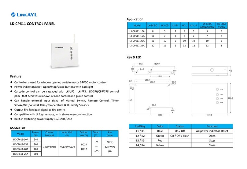
LinkAYL LK-CP611 User manual

LinkAYL
LinkAYL LK-CP63 Series User manual
LinkAYL
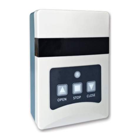
LinkAYL LK-CP711-30A User manual
LinkAYL
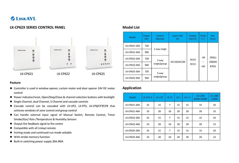
LinkAYL LK-CP62 Series User manual
LinkAYL
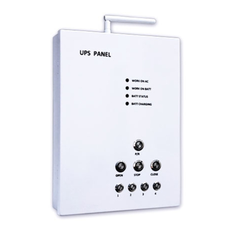
LinkAYL LK-UP24 Series User manual
LinkAYL
LinkAYL LK-CP63X Series User manual
LinkAYL
LinkAYL LK-FP3 User manual
LinkAYL
LinkAYL LK-CP64 Series User manual
LinkAYL
LinkAYL LK-UP211 User manual
Popular Control Panel manuals by other brands
Siemens
Siemens SXL-EX datasheet
DEA SYSTEM
DEA SYSTEM NET24N Operating instructions and warnings
Menvier Security
Menvier Security TSD402 Installation & user guide
LEGRAND
LEGRAND Valena 7700 66 installation instructions
ETC
ETC echoflex Elaho Preset Station installation guide

NAPCO
NAPCO Magnum Alert 2600 operating guide
