erowa PowerChuck P without base plate User manual

1
STANDARDIZATION
WORKHOLDINGSYSTEMS
PowerChuck
ER-115800
3
PowerChuck P
ohne Grundplatte
Sicherheit, Garantie, Haftung
und Serviceadressen siehe Bei-
lage A.
Verpackungsinhalt
überprüfen
1x PowerChuck P ohne
Grundplatte (montiert)
1x O-Ring ø 30 x 1,5 mm
(lose beigelegt)
6x Zylinderschrauben M10 x 30
(lose beigelegt)
2x Zylinderstift ø 10h8 x 20
(lose beigelegt)
1x Viton-Dichtung
ø 18.5 / 12 x 9mm
(lose beigelegt)
1x Dichtringzentrierung
(lose beigelegt)
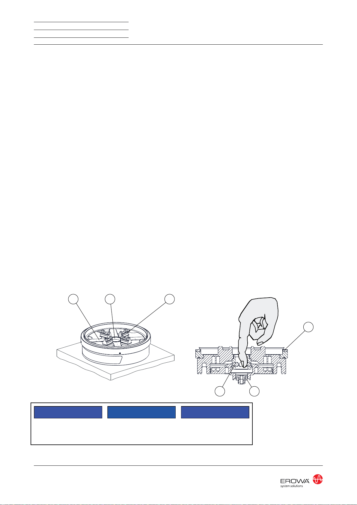
HINWEIS
Die Zentrierprismen (3) müssen
beim Einsetzen von P Paletten
immer mit einem leichten Fett-
film versehen sein!
Das geeignete Fett um die
Zentrierprismen leicht zu fetten
ist das Staburags NBU 12 von
Klüber oder ein gleichwertiges
Montagefett.
Das PowerChuck P dient zur
Aufnahme von Paletten ø 115 /
ø 148 / PM85 und Elektroden-
haltern.
EROWA Spannfutter werden ver-
wendet um Werkstückträger und
Werkstückspanner zu halten.
PowerChuck P
without base plate
For safety, guarantee, liability
and service addresses, see Ap-
pendix A.
Check package contents
1x PowerChuck P without
base plate (fitted)
1x O-ring ø 30 x 1.5 mm
(loose enclosed)
6x Socket head bolt M10 x 30
(loose enclosed)
2x Pin ø 10h8 x 20
(loose enclosed)
1x Viton seal
ø 18.5 / 12 x 9mm
(loose enclosed)
1x Sealing ring centering
(loose enclosed)
NOTICE
With the use of P pallets the cen-
tering prisms (3) should always
wear a slight cover of grease!
The suitable grease for greasing
slightly the centering prisms is
Staburags NBU 12 from Klüber
or an equivalent assembly
grease.
The PowerChuck P serves to ac-
commodate pallets ø 115 / ø 148 /
PM85, as well as pallets and elec-
trode holders.
EROWA chucks are used to hold
workpiece carriers and work-
piece clamping systems.
DOC-130459-02
PowerChuck P
sans plaque de base
Sécurité, garantie, responsabi-
lités et adresses de service : voir
annexe A.
Vérifier l'intégralité de la li-
vraison
1x PowerChuck P sans
plaque de base (montée)
1x Joint torique ø 30 x 1,5 mm
(en vrac inclus)
6x Vis à tête cylindrique M10 x 30
(en vrac inclus)
2x Goupille cylindrique
ø 10h8 x 20
(en vrac inclus)
1x Joint d'étanchéité Viton
ø 18.5 / 12 x 9mm
(en vrac inclus)
1x Centrage joint d'étanchéité
(en vrac inclus)
INDICATION
En utilisation avec P palettes les
prismes de centrage (3) doivent
toujours être couvert avec une
légère couche de graisse !
La graisse appropriée pour grais-
ser légèrement les prismes de
centrage est la graisse Staburags
NBU 12 de Klüber ou une graisse
de montage équivalente.
Le mandrin PowerChuck P
sert à fixer des palettes ø 115 /
ø 148 / PM85, ainsi que des
palettes et des porte-électrode.
Utilisation (conformément à sa
destination)
Anwendung (bestimmungsge-
mässe Verwendung) Application (intended purpose)
Les mandrins EROWA sont
utilisés pour maintenir le porte-
pièce et le dispositif de serrage
de pièce.

2STANDARDIZATION
WORKHOLDINGSYSTEMS ER-115800
Steht für eine unmittelbar drohende Ge-
fahr, die zu schweren, irreversiblen Kör-
perverletzungen oder zum Tod führt.
Steht für eine möglicherweise gefährliche
Situation, die zu schweren Körperverlet-
zungen führen kann.
Steht für eine möglicherweise gefährliche
Situation, die zu leichten Körperverletzun-
gen führen kann.
Steht für eine möglicherweise schädliche
Situation, bei der das Produkt oder eine
Sache in seiner Umgebung beschädigt
werden könnte.
Steht fürAnwendungshinweise und ande-
re nützliche Informationen.
GEFAHR
WARNUNG
VORSICHT
HINWEIS
WICHTIG
Das EROWA Produkt wurde nach den all-
gemein anerkannten Regeln der Technik
und dem aktuellen Stand von Wissen-
schaft und Technik gefertigt. Dennoch ge-
hen von Maschinen Risiken aus, die sich
konstruktiv nicht vermeiden lassen. Um
dem mit dem EROWA Produkt arbeiten-
den Personal ausreichend Sicherheit zu
gewährleisten, werden zusätzlich Sicher-
heitshinweise gegeben. Nur wenn diese
beachtet werden, ist hinreichende Sicher-
heit beim Umgang mit dem EROWA Pro-
dukt gewährleistet. Bestimmte Textstellen
sind besonders hervorgehoben. Die so
gekennzeichneten Stellen haben folgen-
de Bedeutung:
Symbolerklärung
Highlights an immediate thread of danger
that will cause serious, irreversible physi-
cal injury or death.
Highlights a possible dangerous situation
that could cause serious physical injury.
Highlights a possible dangerous situation
that could cause minor physical injury.
Highlights a possible harmful situation in
which the product or an object in the vicin-
ity could be damaged.
Highlights information on usage and other
useful information.
The EROWA Product has been manufac-
tured according to the generally recog-
nized rules of technology and the state of
the art of science and technology. Even
so, machines involve risks which cannot
be avoided by means of design and con-
struction. In order to provide personnel
working with the EROWA Product with ad-
equate safety, additional precautions are
provided. Adequate safety at work with
the EROWAProduct can only be ensured
if these precautions are being followed.
Certain passages have been marked in a
particular way. The passages marked in
this manner have the following meaning:
DANGER
WARNING
CAUTION
NOTICE
IMPORTANT
Explanation of the symbols
DOC-130459-02
Signale un danger qui vous menace
directement et qui provoque de graves
blessures corporelles ou la mort.
Signale une situation potentiellement
dangereuse susceptible de provoquer de
graves blessures corporelles.
Signale une situation potentiellement
dangereuse susceptible de provoquer
des blessures corporelles légères.
Signale une situation potentiellement
néfaste dans laquelle le produit ou un
objet placé à proximité de lui risque d’être
endommagé.
Signale des consignes d’utilisation et
d’autres informations utiles.
Le Produit EROWA a été conçu en fonc-
tion des règles techniques généralement
admises et de l’état actuel des connais-
sances scientifiques et techniques. Il
n’en reste pas moins que toute machine
présente nécessairement des risques qui
ne peuvent pas être entièrement éliminés
par la seule approche conceptuelle. D’où
la prescription de consignes de sécu-
rité spécifiques pour assurer une sécurité
maximale au personnel travaillant sur le
Produit EROWA. Seule l’observation
de ces consignes de sécurité permet
d’assurer une sécurité suffisante aux per-
sonnes dans leurs rapports avec le Pro-
duit EROWA. Certains passages ont été
mis en évidence. Ils ont les significations
suivantes :
DANGER
AVERTISSEMENT
ATTENTION
INDICATION
IMPORTANT
Description des symboles utilisés

3
STANDARDIZATION
WORKHOLDINGSYSTEMS
PowerChuck
ER-115800
WARNUNG
Unsachgemässe Bedienung,
fehlerhafte Manipulation oder
fehlerhaftes Material (herun-
terfallen von Teilen, Lärm) kön-
nen zu schweren Körperverlet-
zungen führen.
Der Bediener ist aufgefordert
die vorhandene persönliche
Schutzausrüstung (z.B. Schutz-
brille, Schutzschuhe und Gehör-
schutz) korrekt zu tragen.
GEFAHR
Unvorhersehbare Fehlfunkti-
onen oder fehlerhaftes Material
des Produkts (wegfliegen von
Teilen), können zu schweren
und irreversiblen Körperverlet-
zungen führen.
Die vorhandenen Schutzeinrich-
tungen sind gemäss der Betrieb-
sanleitung (Werkzeugmaschine)
korrekt und konsequent anzu-
wenden.
Schutzeinrichtungen
Persönliche Schutzausrüstung
HINWEIS
Die Auswahl und die Prüfung
über den Einsatz der einzelnen
Schutzausrüstungsgegenstän-
de hat durch den Betreiber zu
erfolgen.
WARNUNG
Maximaler Reinigungsdruck be-
achten.
Zu starkes Abblasen und Lärm
mit der Druckluft vermeiden,
Gehörschutz tragen.
Gegen Augenverletzungen gut
sitzende Schutzbrille tragen
(auch Drittpersonen). Gefähr-
dung durch Versprühen von
Flüssigkeit und wegfliegenden
Spänen, etc.
Müssen Teile beim Abblasen in
der Hand gehalten werden, sind
geeigneteHandschuhezutragen.
Arbeiten mit Druckluft
WARNING
Improper operation, erroneous
manipulation or faulty material
(falling parts, noise) can lead to
serious personal injury.
The operator is requested to
properly wear the existing per-
sonal protective equipment
(e.g., goggles, protective shoes,
and hearing protection).
DANGER
Unforeseeable malfunctions or
faulty material of the product
(parts being thrown out) can
cause severe and irreversible
injury.
The existing protection devices
must be used properly and con-
sistently according to the operat-
ing instructions (machine tool).
NOTICE
The operating company is re-
sponsible for the selection and
verification of use of the individ-
ual protection equipment.
Protection devices
Personal protective equipment
WARNING
Be sure to observe the maxi-
mum cleaning pressure.
Avoid excessive blowing and
noise with compressed air, wear
hearing protection.
To avoid eye injuries, wear
properly fitting safety glasses
(including third parties). Risk of
spraying liquid and projection of
chips, etc.
If you must hold any parts in
your hand while blowing them
off, wear suitable gloves.
Working with compressed air
DOC-130459-02
AVERTISSEMENT
Toute utilisation non conforme,
manipulation erronée ou ma-
tériau défectueux (chutes de
pièces, bruit) peut entraîner de
lourdes blessures corporelles.
L’opérateur est prié de porter
correctement les équipements
de protection individuelle ex-
istants (lunettes de sécurité,
chaussures de sécurité, protec-
tion auditive, etc.).
DANGER
Des dysfonctionnements im-
prévisibles ou un matériau dé-
fectueux dans le produit (pièces
qui s’échappent) peuvent en-
traîner des blessures corpo-
relles lourdes et irrémédiables.
Les dispositifs de protection ex-
istants doivent donc être utilisés
systématiquement et conformé-
ment aux instructions de service
(de la machine-outil).
Équipement de protection
individuelle
INDICATION
L’exploitant est responsable de
la sélection et du contrôle des
différents équipements de pro-
tection individuelle.
Dispositifs de protection
AVERTISSEMENT
Observer la pression de netto-
yage maximale.
Éviter un nettoyage par souffla-
ge et bruit à trop forte pression,
porter une protection auditive.
Porter des lunettes de sécurité
bien ajuster pour éviter toute
blessure des yeux (tierces per-
sonnes également). Risque de
pulvérisation de liquides et de
projection de copeaux, etc.
Si le nettoyage exige de tenir
des pièces à la main, porter des
gants appropriés.
Travailler avec de l’air comprimé
4STANDARDIZATION
WORKHOLDINGSYSTEMS ER-115800
1
23
4
7
6
4
5
8
910
11
12
13
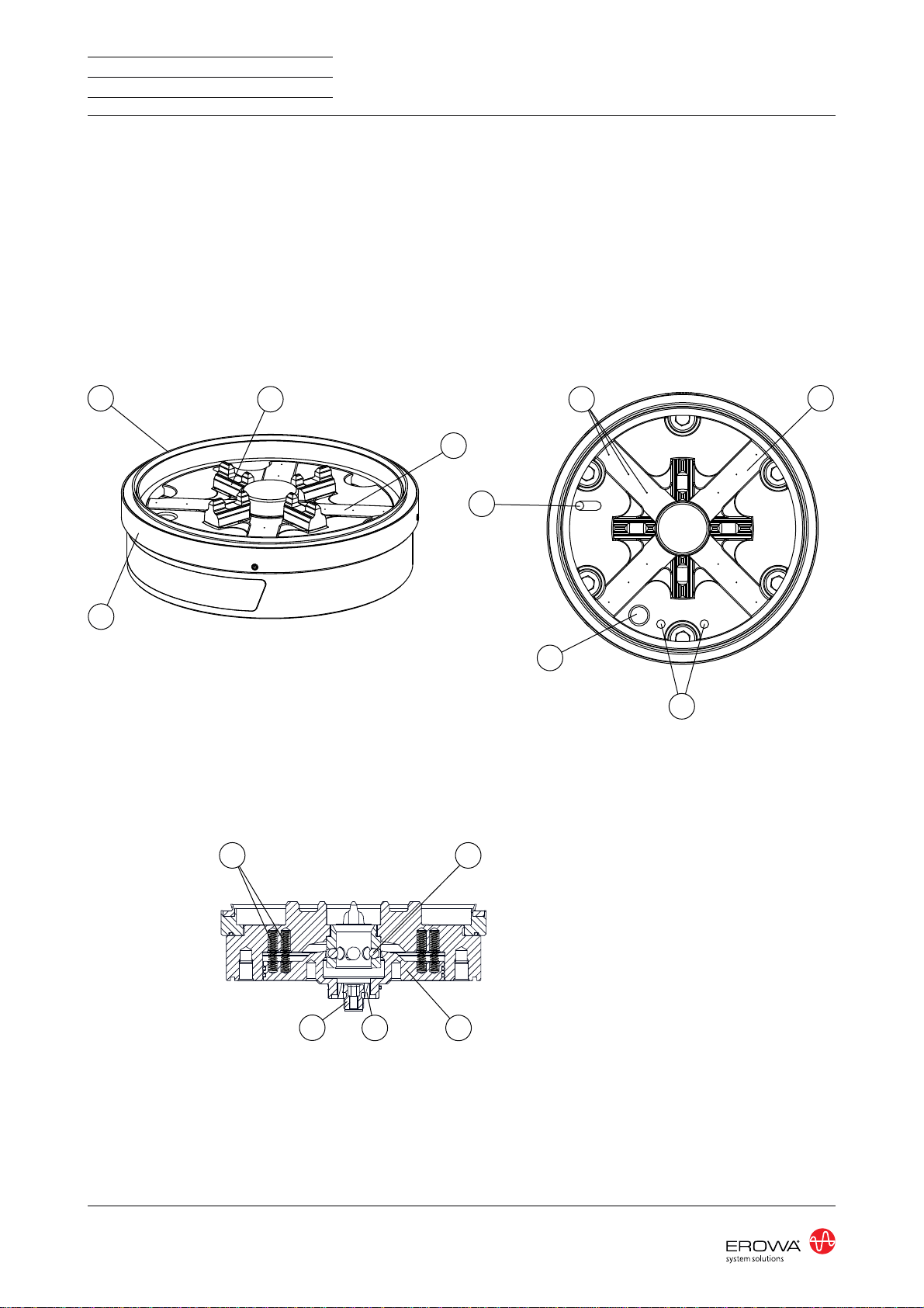
Bezeichnung der Teile
1) Dichtringhalter
2) Späneschutz ø 148
3) Zentrierprismen
4) Z-Auflage
5) Referenzmarken
6) Bohrung für Lageorientie-
rung
7) Bohrung für Reinigung und
Überwachung
8) Entlüftung und Wasser-
ablauf
9) Druckfeder
10) Kugel
11) Kolben
12) Viton-Dichtung
13) Dichtringzentrierung
Description of parts
1) Sealing ring holder
2) Chip guard ø 148
3) Centering prisms
4) Z-Supports
5) Reference marks
6) Borehole for position orien-
tation
7) Borehole for cleaning and
monitoring
8) Ventilation and liquid drain-
age
9) Compression spring
10) Ball
11) Piston
12) Viton seal
13) Sealing ring centering
DOC-130459-02
Désignation des éléments
1) Monture de bague
d'étanchéité
2) Protection contre les co-
peaux ø148
3) Prismes de centrage
4) Appuis Z
5) Points de référence
6) Alésage pour l'orientation
de la position
7) Alésage pour le nettoyage
et la surveillance
8) Purge d'air et vidange de
liquide
9) Ressort de compression
10) Bille
11) Piston
12) Joint d'étanchéité Viton
13) Centrage joint d'étanchéité

5
STANDARDIZATION
WORKHOLDINGSYSTEMS
PowerChuck
ER-115800
ø 126.8
6 x 60°
ø 149.8
6x M10
2x ø 10
33
9.7
(46.5)
14.7
6 bar
10'000 N (Tol. -10%)
4 x 90°
3 bar
+5° bis +70° C
ISO 8573.1
0.002 mm
3.6 kg
Technische Daten
P2) Öffnen / Schliessen
Indexierung der Palette:
Spannkraft:
Druckluft:
Automatisierbar: ja
WICHTIG
Die Spannkraft gilt ab Werk.
Gespannt: Drucklos
P3) Reinigen / Überwachen
Druckluftqualität Klasse 4:
Wir empfehlen die Luftversorgung
über eine Wartungseinheit mit Öl
und Wasserabscheider zu führen.
Betriebstemperatur:
Repetiergenauigkeit:
Gewicht:
Technical data
P2) Open / Close
Indexation of pallet:
Clamping power:
Air pressure:
Automatable: yes
IMPORTANT
The clamping force applies ex
works.
Locked: Depressurized
P3) Cleaning / Monitoring
Quality of compressed air class 4:
We recommend to feed the air-
supply through a unit with oil and
waterseparator.
Operating temperature:
Repeatability:
Weight:
DOC-130459-02
Caractéristiques techniques
P2) Ouvrir / Fermer
Force de serrage :
Pression d'air comprimé :
Automatisable : oui
Indexation de la palette :
IMPORTANT
La force de serrage s'applique
départ usine.
Serrage : Par dépressurisation
P3) Nettoyer / Surveillance
Qualité de l'air comprimée classe 4 :
Nous recommandons d'alimenter
l'air comprimé par une unité avec
séparateur de l'huile et d'eau.
Temperature d'operation :
Précision de répétabilité :
Poids :

6STANDARDIZATION
WORKHOLDINGSYSTEMS ER-115800
14
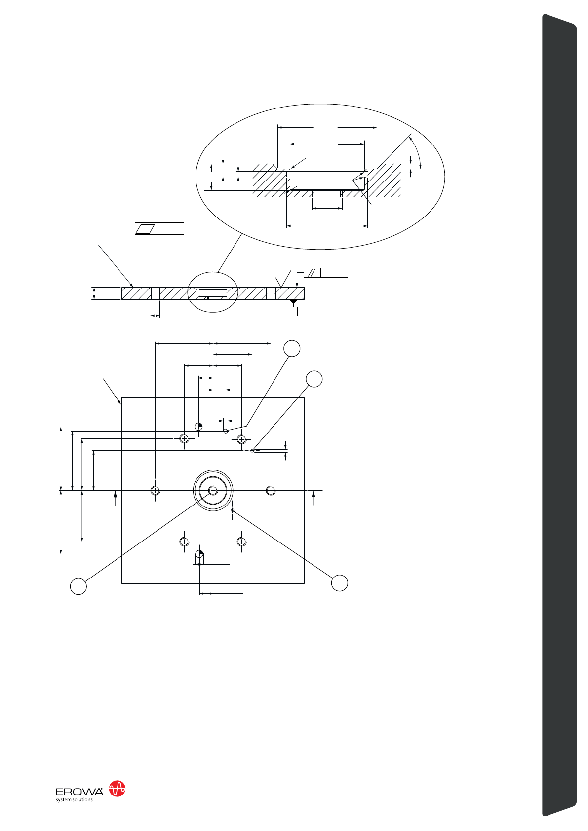
HINWEIS
Platte/Vorrichtung nach Zeich-
nug Seite 7 fertigen.
Der Montagezapfen (14) darf
erst nach der Montage des
Spannfutters auf die Montagflä-
che entfernt werden.
DasAussenmass der Platte/Vor-
richtung sollte min. ø149,5 mm
betragen.
Die Montagefläche muss auf N5
überschliffen werden.
Die Montagefläche muss aus
Stahl sein.
Die Position der Anschlussboh-
rungen P2 und P3 auf der Mon-
tagefläche sind nach Zeichnung
Seite 7 zu fertigen.
Die Anschlussbohrungen zu P2
und P3 können kundenspezi-
fisch angebracht werden.
- P2 = öffnen / schliessen
- P3 = reinigen / überwachen
Inbetriebnahme
Bitte beachten Sie vor der
Montage folgende Hinweise:
NOTICE
Produce plate/fixture according
to the diagram on p. 7
Do not remove the mounting peg
(14) before you have mounted
the chuck onto the mounting
surface.
The outer dimension of the
plate/fixture should be at least
ø149.5mm.
The mounting surface must be
ground to N5.
The mounting surface must be
made of steel.
The connection boreholes P2
and P3 on the mounting surface
must be drilled in the positions
shown in the diagram on p. 7.
The connection boreholes for P2
and P3 can be customized.
- P2 = open/close
- P3 = cleaning/monitoring
Setting up
Please observe the following
notes before assembly:
DOC-130459-02
INDICATION
Fabriquer la plaque ou le gabarit
selon le dessin de la page 7.
Le tenon de montage (14) ne
doit être enlevé qu’après mon-
tage du mandrin sur la surface
de montage.
La dimension hors tout de
la plaque ou du gabarit doit
être égale ou supérieure à
ø149,5 mm.
La surface de montage doit être
rectifiée à N5.
La surface de montage doit être
en acier.
Prévoir les positions des orifices
de raccordement P2 et P3 sur la
surface de montage conformé-
ment au dessin de la page 7.
Les orifices de raccordement P2 et
P3 peuventégalement être réalisés
selon les spécifications du client.
- P2 = ouverture / fermeture
- P3 = nettoyage / surveil-
lance
Mise en service
Avant montage, se conformer
aux directives suivantes :
7
STANDARDIZATION
WORKHOLDINGSYSTEMS
PowerChuck
ER-115800
- Referenzseite Spannfutter
- Reference side, chuck
- Face de référence du mandrin
- Auflagefläche Spannfutter
- Mounting surface, chuck
- Surface d’appui du mandrin
0.005
M 10
min. 15
0.01 A
A
N5
63.4
42.8
31.5 31.5
13
ø 5
ø 3.3
59.3
42.8
62 ± 0.005
62 ± 0.005
55 55
15±0.005
ø10.02H7
63.4
15±0.005
ø 40
0
-1
ø 30
+0.05
0
0.3 x 45° max.
R 0.5 max.
M 12
2
5
10.5
0
-0.2
ø 32.6
+0.05
0
2
45°
0.1 x 45°
8 = Entlüftung
8 = Deaerator
8 = Purge d'air
8
P3 P3 = Reinigen / Überwachen
P3 = Cleaning / Monitoring
P3 = Nettoyage / Surveillance
P2 3 gႇQHQ6FKOLHVVHQ
P2 = Open / Close
P2 = Ouverture / Fermeture
19
19 = M12 für Dichtringzentrierung
19 = M12 for sealing ring centering
19 = M12 pour le centrage du joint d'étanchéité
ø 3,3 bohren auf Teilkreis ø 60
Drill ø 3.3 to limb ø 60
Percer des t rous ø 3,3 sur
le cercle de r éférence ø 60
DOC-130459-02

8STANDARDIZATION
WORKHOLDINGSYSTEMS ER-115800
9 ±0.05
1
A
B
17 15
13
18
19
1
Platte / Vorrichtung vorbereiten
(Bild A)
Montagefläche bearbeiten nach
Zeichnung Seite 7.
Montagefläche vor Montage
sauber reinigen.
Zylinderstifte ø10h8x20 (17)
montieren.
O-Ring ø 30 x 1,5 (15) in
Nute (19) einsetzen.
Bei bedarf von aktiver Spülung
durch Spannfutter, Viton-Dich-
tung (18) und Dichtringzentrie-
rung (13) montieren.
Vor der Montage des Spannfut-
ters auf die Montagefläche muss
der Dichtringhalter (1) demon-
tiert werden.
(Bild B)
Prepare plate / fixture
(Diagram A)
Machine mounting surface ac-
cording to the diagram on p. 7.
Thoroughly clean mounting sur-
face before assembly.
Fit pins ø10h8x20 (17).
Insert O-ring ø 30 x 1,5 (15) into
groove (19).
If active flushing through chuck
is required, insert viton seal (18)
and sealing ring centering (13).
Before mounting the chuck on
the mounting surface, remove
seal ring holder (1).
(Diagram B)
DOC-130459-02
Préparation de la plaque ou
du gabarit (figure A)
Usiner la surface de montage
conformément au dessin de la
page 7.
Avant montage, nettoyer soigneu-
sement la surface de montage.
Monter les goupilles cylindriques
ø10h8x20 (17).
Insérer le joint torique ø 30 x 1,5
(15) dans la rainure (19).
Si un rinçage à travers le man-
drin est nécessaire, insérer le
joint viton (18) et la centrage
joint d'étanchéité (13).
Avant montage du mandrin
sur la surface de montage, il
convient de démonter la mon-
ture de joint d’étanchéité (1).
(figure B)

9
STANDARDIZATION
WORKHOLDINGSYSTEMS
PowerChuck
ER-115800
C
D
16 45 Nm
5P3
P2
P2
14
WICHTIG
Bei der Positionierung des Pow-
erChuck P muss beachtet wer-
den, dass sich die Referenzmar-
ken (5) und die Anschlussboh-
rungen P2 und P3 in der richti-
gen Lage zueinander befinden
(siehe Bild C).
(Bild C)
Spannfutter auf Montagefläche
(gereinigt und eingeölt) aufset-
zen und mit den mitgelieferten
M10 Schrauben (16) befestigen.
Schrauben mit Drehmoment von
45 Nm festziehen.
(Bild D)
Spannfutter öffnen (P2 = 6 bar)
und Montagezapfen (14) entfer-
nen.
IMPORTANT
When positioning the Power-
Chuck P, make sure that refer-
ence marks (5) and connection
boreholes P2 and P3 are in the
right position with reference to
each other (cf. diagram C).
(Diagram C)
Clean and oil mounting surface,
place chuck on it and attach
chuck with the M10 bolts (16)
supplied.
Tighten bolts to a torque of
45 Nm.
(Diagram D)
Open chuck (P2 = 6bar) and re-
move mounting peg (14).
DOC-130459-02
IMPORTANT
Lors du positionnement du man-
drin PowerChuck P, il convient
de veiller à ce que les marques
de référence (5) et les orifices
de raccordement P2 et P3
soient en bonne position les uns
par rapport aux autres. (Se réfé-
rer au figure C.)
(figure C)
Placer le mandrin sur la surface
de montage (nettoyée et huilée).
Le fixer avec les vis M10 (16),
faisant partie de la livraison.
Serrer les vis avec un couple de
serrage de 45 Nm.
(figure D)
Ouvrir le mandrin (P2 = 6 bar)
et enlever le tenon de montage
(14).
10 STANDARDIZATION
WORKHOLDINGSYSTEMS ER-115800
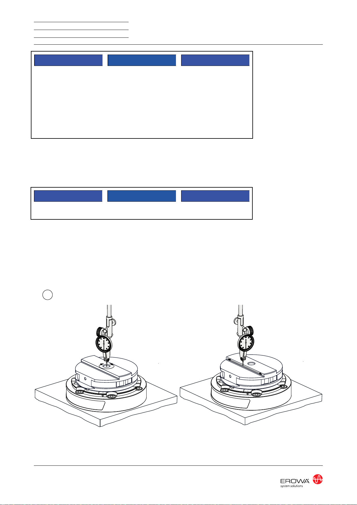
D
HINWEIS
Wird die gewünschte Lageto-
leranz des Spannfutters nicht
erreicht, kann das Spannfutter
mit Hilfe der Ausrichtpalette
ER-032819 (Option) ausgerich-
tet werden.
Der Bereich zum Ausrichten
wird beschränkt durch die Posi-
tion der Zylinderstifte ø10 (17).
(siehe Bild A).
(Bild D)
Ausrichtpalette in das Spannfut-
ter einsetzen.
Spannfutter schliessen.
(P2 = 6 bar).
Befestigungsschrauben (18) lö-
sen, bis das Spannfutter in alle
Richtungen frei verschoben wer-
den kann.
Spannfutter mit Hilfe der Aus-
richtpalette ausrichten.
Befestigungsschrauben (18) fest-
ziehen mit Drehmonent 45 Nm.
P2 und P3 müssen jetzt wieder
drucklos sein.
HINWEIS
NOTICE
If you cannot achieve the de-
sired position tolerance of the
chuck, align the chuck with
the help of alignment plate
ER-032819 (option).
The alignment range is lim-
ited by the position of the pins
ø10 (17).
(cf. diagram A).
Loosen attachment bolts (18)
until the chuck can be freely
moved in all directions.
Align chuck with the help of the
alignment plate.
Tighten attachment bolts (18) to
a torque of 45 Nm.
(Diagram D)
Insert alignment plate into
chuck.
Close chuck
(P2 = 6 bar).
P2 and P3 must now be without
pressure again.
NOTICE
DOC-130459-02
INDICATION
Si la tolérance de positionne-
ment du mandrin n’est pas at-
teinte, ce dernier peut être posi-
tionné au moyen de la palette de
positionnement ER-032819 (en
option).
La zone disponible pour le
positionnement est limitée par
la position des goupilles cylin-
driques ø10 (17). (Se référer à la
figure A) .
Desserrer les vis de fixation
(18) jusqu’à ce que le mandrin
puisse être déplacé librement
dans toutes les directions.
Positionner le mandrin au moyen
de la palette de positionnement.
Serrer les vis de fixation (18) à
45 Nm.
(figure D)
insérer la palette de positionne-
ment dans le mandrin.
Fermer le mandrin
(P2 = 6 bar).
P2 et P3 doivent alors être à
nouveau dépressurisées.
INDICATION
11
STANDARDIZATION
WORKHOLDINGSYSTEMS
PowerChuck
ER-115800
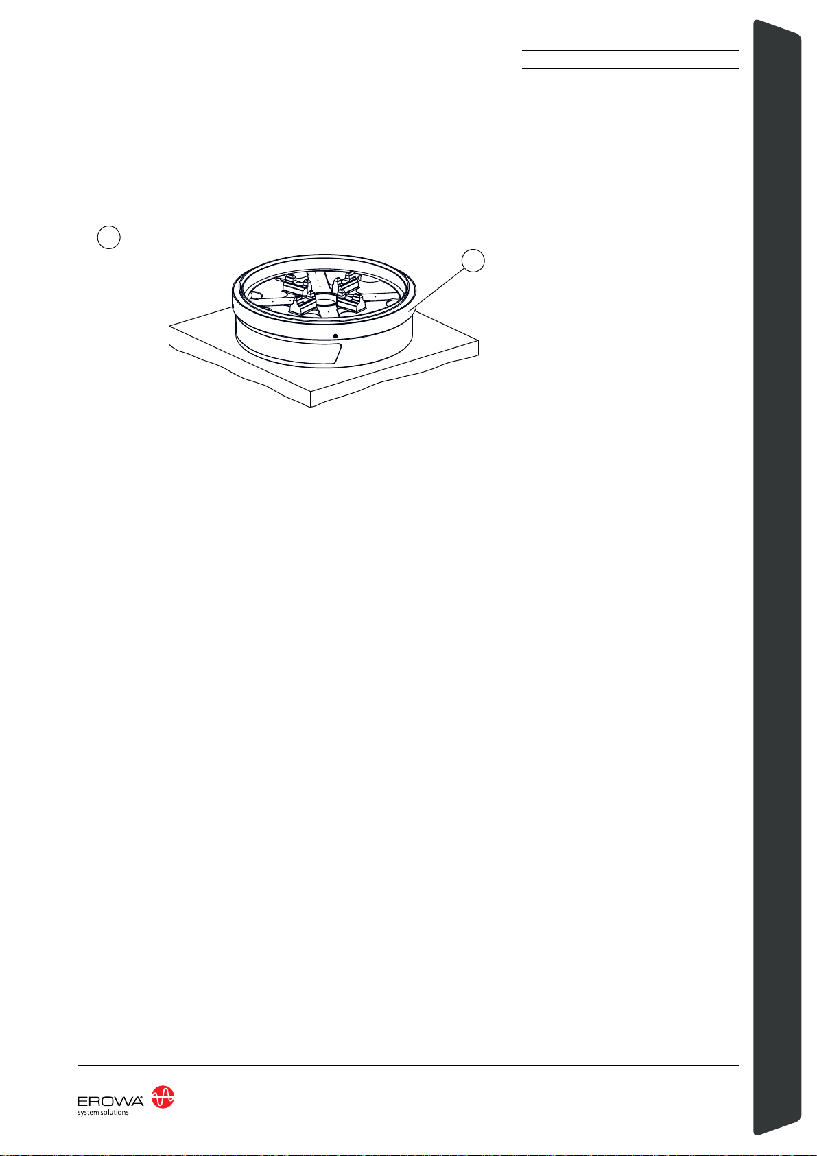
E
1
(Bild E)
Ausrichtpalette entfernen und
Dichtringhalter (1) wieder mon-
tieren.
Das PowerChuck P ist nun
betriebsbereit.
(Diagram E)
Remove alignment plate and put
back seal ring holder (1).
The PowerChuck P is now
operational.
DOC-130459-02
(figure E)
Enlever la palette de positionne-
ment et remonter la monture de
joint d’étanchéité (1).
Le mandrin PowerChuck P est
maintenant prêt à être utilisé.
12 STANDARDIZATION
WORKHOLDINGSYSTEMS ER-115800
10
20 3
4
12
2
Instandhaltung, Wartung
Vor Inbetriebnahme Flanken der
Zentrierprismen (3) leicht einfet-
ten.
Das geeignete Fett um die
Zentrierprismen leicht zu fetten
ist das Staburags NBU 12 von
Klüber oder ein gleichwertiges
Montagefett.
Kugeln (10) wöchentlich fetten.
Zentrierprismen (3) und Z-Auf-
lagen (4) reinigen und gegen
Beschädigung durch Schläge
schützen.
Viton-Dichtung ER-005070 (12)
und Späneschutz ø148
ER-014687 (2), sofern hart oder
spröde, ersetzen.
Wöchentliche Wartung
Konus reinigen (20).
Sichtkontrolle auf äussere Be-
schädigung von Gehäuse, Ku-
geln, Z-Auflagen, Zentrierpris-
men, Pneumatikschläuchen.
Überprüfung der Reinigungsfunk-
tion.
Nach Gebrauch Spannfutter
reinigen und gegen Korrosion
schützen.
HINWEIS
Wir empfehlen die Überho-
lung der PowerChuck P nach
200'000 Spannzyklen oder nach
3 Jahren.
Maintenance
Before operating the Power-
Chuck, slightly grease the sides
of the centering prisms (3).
The suitable grease for greasing
slightly the centering prisms is
Staburags NBU 12 from Klüber
or an equivalent assembly
grease.
Grease balls weekly (10).
Clean and protect centering
prisms (3) and Z-supports (4)
against damage through knocks.
Replace Viton seal ER-005070
(12) and chip guard ER-014687
(2) when hard or brittle.
Weekly maintenance
Cleaning the taper (20).
Visual inspection for external
damage to housings, balls, Z-
supports, centring prisms, pneu-
matic hoses.
Checking the cleaning function.
Clean the chuck after use and
protect it against corrosion.
NOTICE
We recommend an overhaul of
the PowerChuck P after 200'000
clamping cycles or after 3 years.
DOC-130459-02
Maintenance
Avant mise en service, grais-
ser légèrement les flancs des
prismes de centrage (3).
La graisse appropriée pour grais-
ser légèrement les prismes de
centrage est la graisse Staburags
NBU 12 de Klüber ou une graisse
de montage équivalente.
Graisser les billes une fois par
semaine (10).
Nettoyer et protéger les prismes
de centrage (3) et les appuis Z
(4) contre les dommages dus
aux chocs.
Remplacer le joint Viton
ER-005070 (12) et la protection
contre les copeaux ER-014687
(2), dans la mesure où ils ont
durci et sont devenus cassants.
Maintenance hebdomadaire
Nettoyage du cône (20).
Contrôle visuel des dom-
mages externes sur les boî-
tiers, les billes, les supports en
Z, les prismes de centrage, les
flexibles pneumatiques.
Vérification de la fonction de
nettoyage.
Nettoyer le mandrin après uti-
lisation et le protéger contre la
corrosion.
INDICATION
Nous vous recommandons de
révisionner les PowerChuck P
après 200.000 cycles de bridage
ou après 3 ans.

13
STANDARDIZATION
WORKHOLDINGSYSTEMS
PowerChuck
ER-115800
ER-115895
ER-115749
Wartungsanleitung
Bei übermässiger Abnutzung
oder Beschädigung kann auch
das Gehäuse des PowerChuck
P ersetzt werden.
Eine vollständige Anleitung zur
Überholung der PowerChuck P
liegt dem Reparaturkit bei.
Störungen, Fehlerbehebungen
F = Fehler,
U =mögliche Ursache,
B = Behebung
F: Spannfutter lässt sich nicht
öffnen.
U1: Reinigungsdruckluft P3 ist
zu gross.
B1: Reinigungsdruck P3 auf
3 bar drosseln
(ER-008988 = D1).
U2: Eingangsdruck P2 zu ge-
ring.
B2: Eingangsdruck P2 auf min.
6 bar erhöhen.
F: Repetiergenauigkeit stimmt
nicht.
U1: Dichtring (2) und Viton-
Dichtung(12) zu hart.
B1: Dichtring (2) ER-014687
und Viton-Dichtung (12)
ER-005070 ersetzen.
U2: Bei Bedienung mit Luft-
pistole: Spannfutter nicht
komplett entlüftet.
B2: Spannfutter ganz entlüften.
F: Palette vibriert beim Ein-
spannen
U1: Überdruckentlüftung ge-
schlossen / verstopft.
B1: Überdruckentlüftung
öffnen / reinigen.
U2: Reinigungsdruckluft P3 ist
zu gross.
B2: Reinigungsdruck P3 auf
3 bar drosseln
(ER-008988 = D1).
Maintenance Manual
At the same time, check the
casing of the PowerChuck P for
wear or damage and replace if
necessary.
Acomprehensive manual for the
overhaul of the PowerChuck P is
included in the Repairkit.
Failures: cause and action
F = failure,
C =possible cause,
A = action
F: Chuck cannot be opened.
C1: Cleaning air pressure P3
too high.
A1: Reduce cleaning pressure
P3 to 3 bar
(ER-008988 = D1).
C2: Supply pressure P2 too
low.
A2: Increase supply pressure
P2 to min. 6 bar.
F: Repeatability not right.
C1: Sealing ring (2) ring and Vi-
ton seal too hard.
A1: Replace seal ring (2)
ER-014687. and Viton seal
(12) ER-005070
C2: With air gun operation:
chuck not completely de-
aerated.
A2: Completely deaerate
chuck.
F: Pallet vibrates on being
clamped.
C1: Overpressure vent closed/
clogged up.
A1: Open / clean overpressure
vent.
C2: Cleaning air pressure P3
too high.
A2: Reduce cleaning pressure
P3 to 3 bar
(ER-008988 = D1).
DOC-130459-02
Manuèl de Maintenance
Dans le même temps, vérifiez
le boîtier du PowerChuck P
d'usure ou de dommages et le
remplacez si nécessaire.
Un manuel détaillé pour la révi-
sion de la PowerChuck P est
inclus dans le kit de réparation.
Pannes, dépannage
F = Faut,
C =Cause possible,
D =Dépannage
E : Impossible d’ouvrir le man-
drin
C1 : Pression pneumatique de
nettoyage P3 trop élevée.
D1 : Étrangler la pression pneu-
matique de nettoyage P3 à
3 bar (ER-008988 = D1) .
C2 : Pression pneumatique à
l’entrée P2 trop faible.
D2 : Augmenter la pression
pneumatique à l’entrée P2
au min. à 6 bar.
E : Précision de répétabilité
insuffisante.
C1 : Joint d’étanchéité (2) et
joint d'étanchéité Viton trop
dur.
D1 : Remplacer le joint d’étan-
chéité (2) ER-014687 et le
joint Viton (12) ER-005070.
C2 : Air non entièrement purgé
en conduite avec pistolet
pneumatique.
D2 : Purger entièrement le man-
drin.
E : La palette vibre lors du ser-
rage.
C1: Purge d’air en surpression
fermée ou bouchée.
D1: Ouvrir et nettoyer la purge
d’air en surpression.
C2: La pression pneumatique
de nettoyage P3 est trop
élevée.
D2: Étrangler la pression pneu-
matique de nettoyage P3 à
3 bar (ER-008988 = D1).
14 STANDARDIZATION
WORKHOLDINGSYSTEMS ER-115800
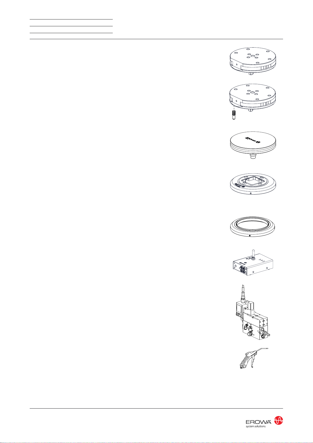
Optionen
ER-115308
Palette ø 148 G
ER-008972
Abdeckung für PowerChuck P,
für fest installierte Spannfutter,
die nicht in Gebrauch sind.
Die Abdeckung ist keine
Palette!
ER-092203
Dichtring PowerChuck P / ITS
50 C manuell
Über die Standard Halter ge-
stülpt, wird die Verschmutzung
des PowerChuck verhindert.
ER-016142
Dichtring PowerChuck P / ø 115
manuell
ER-046221
Referenzschraube
(Satz à 10 Stück)
Sie dient dazu, dass die Palette
immer in der gleichen Lage ins
PowerChuck P eingesetzt wird.
ER-008988
Manuelle Steuereinheit
Zur einfachen Betätigung des
PowerChuck im manuellen Be-
trieb. Alle Anschlüsse und 3 m
Schläuche werden mitgeliefert.
ER-070445
Steuereinheit mit Überwachung
Für die Betätigung des Power
Chuck über die CNC-Steuerung.
Alle Anschlüsse und 3m Schläu-
che werden mitgeliefert.
ER-001846
Blaspistole
Options
ER-115308
Pallet ø 148 G
ER-008972
Cover for PowerChuck P, for
fixed chucks which are not in
use.
This cover is not a pallet!
ER-092203
Sealing ring ITS 50 C for Power-
Chuck P manual
Put over the standard holder,
this guard prevents the Power
Chuck from getting dirty.
ER-016142
Sealing ring PC P / ø 115
manual
ER-046221
Reference bolt
(Set of 10)
This bolt ensures that the pallet
is always inserted into the Pow-
erChuck P in the same position.
ER-008988
Manual control unit
For simple operation of the Pow-
erChuck in the manual mode.All
the connections and 3m tubes
are supplied.
ER-070445
Control unit with monitoring
To operate the PowerChuck
through the CNC control. All the
connections and 3m tubes are
supplied.
ER-001846
Air jet
DOC-130459-02
Options
ER-115308
Palette ø 148 G
ER-008972
Couvercle pour PowerChuck P
installés à poste fixe, et qui ne
sont pas en service.
Le couvercle n'est pas une
palette!
ER-092203
Joint d’étanchéité ITS 50 C
PowerChuck P manuelle
Embouti suivant la forme des
supports classiques, il évite
l'encrassement du PowerChuck.
ER-016142
Joint d’étanchéité ø 115
PowerChuck P manuelle
ER-046221
Doigt de référence
(jeu de 10 unités)
Il permet de monter la palette
toujours dans la même position
dans le mandrin PowerChuck P.
ER-008988
Unité de commande manuelle
Pour faciliter la manoeuvre ma-
nuelle du PowerChuck. Tous les
raccords sont livrés, avec 3m de
tuyau.
ER-070445
Unité de commande avec sur-
veillance
Pour la manoeuvre du Power
Chuck par l'intermédiaire de la
commande CNC. Tous les rac-
cords sont livrés, ainsi que 3m
de tuyau.
ER-001846
Pistolet d'air

15
STANDARDIZATION
WORKHOLDINGSYSTEMS
PowerChuck
ER-115800
ER-010723
Kontrolldorn 50
ER-008617
Messdorn
ER-115699
Ausrichtpalette ø 115 MS
ER-116632
Ausrichtpalette P ø 148 Inox
Optionen
Weitere Produkte finden Sie im
Gesamtkatalog und auf unserer
Webseite www.erowa.com.
WICHTIG
ER-010723
Checking pin 50
ER-008617
Gaugin pin
ER-115699
Alignment pallet ø 115 MS
ER-116632
Alignment pallet P ø 148 Inox
Options
IMPORTANT
More products can be found in
our general catalog and on our
web-page www.erowa.com.
DOC-130459-02
ER-010723
Tasseau de contrôle 50
ER-008617
Tasseau de mesure
ER-115699
Palette d'alignement ø 115 MS
ER-116632
Palette d'alignement P ø 148
Options
IMPORTANT
D'autres produits vous trouvez
également au catalogue général
et à www.erowa.com.

16 STANDARDIZATION
WORKHOLDINGSYSTEMS ER-115800
Ersatzteile
ER-014687
Späneschutz ø 148
mit Dichtlippe
ER-005070
Viton-Dichtung ø18.5/12 x 9mm
ER-115722
Dichtring PowerChuck P / ø 148
manuell
ER-115895
Reparatur Gehäuse
PowerChuck P
ER-115749
Reparatur Kit PowerChuck P
Beziehen Sie Ersatzteile bei Ih-
rem EROWA Fachhändler.
Technischer Support
Für Fragen zu diesem Produkt
kontaktieren Sie bitte:
Spare parts
ER-014687
Chip guard ø 148
with sealing lip
ER-005070
Seal viton ø18.5/12 x 9mm
ER-115722
Seal ring PowerChuck P / ø 148
manuell
ER-115895
Repair casing
PowerChuck P
ER-115749
Repair kit PowerChuck P
Please order spare parts from
your EROWA dealer.
Technical support
For questions regarding this
product, please contact:
DOC-130459-02
Pièces de rechange
ER-014687
Protection contre les copeaux
ø 148 avec lèvre d'étanchéité
ER-005070
Joint viton ø18.5/12 x 9mm
ER-115722
Monture de bague d'étanchéité
ø 148, manuel
ER-115895
Corps de réparation
PowerChuck P
ER-115749
Kit de réparation PowerChuck P
Commandez les pièces de re-
change chez votre agent EROWA.
Assistance technique
Pour toute question relative à ce
produit, veuillez écrire à
I
STANDARDIZATION
WORKHOLDINGSYSTEMS
EC Declaration of incorporation
EROWA AG
Postfach
Knutwilerstrasse
CH-6233 Büron / Switzerland
EROWA Spannfutter
Type: ER-115800
EG Einbauerklärung
Der Hersteller:
erklärt hiermit, dass das Produkt:
den folgenden Bestimmungen entspricht:
EG-Richtlinien:
RICHTLINIE 2006/42/EG,
Anhang II B
Maschinen
17. Mai 2006
einschliesslich späterer Änderungen der
Richtlinien.
EC declaration of incorporation
The manufacturer:
hereby declares that the product:
is in compliance with the following provi-
sions:
EC Directives:
DIRECTIVE 2006/42/EC,
ANNEX II B
Machinery
17 May 2006
including later amendments to the directives.
DOC-130085-00
Déclaration CE d'incorporation
Le fabricant :
déclare par la présente que le produit :
répond aux prescriptions suivantes :
Directives CE :
DIRECTIVE 2006/42/CE,
Annexe II B
Machines
17 mai 2006
modifications subséquentes des directives
comprises.
II STANDARDIZATION
WORKHOLDINGSYSTEMS
29.10.14
Place, Date: Büron,
Dieter Gautschi
Die
ter Gautschi
Die Inbetriebsetzung der unvollständigen
Maschinen (EROWA Spannfutter) ist so-
lange untersagt bis diese zur Gesamtan-
lage zusammengebaut werden.
Sie gelten erst dann gemäss der EG-Maschi-
nenrichtlinie als Maschine.
Die Konformität des EROWASpannfutters ist
nach der Richtlinie 2006/42/EG Anhang II A
gegeben, wenn dieses gemäss der Betriebs-
anleitung angeschlossen, in Betrieb gesetzt
und die Funktion getestet ist.
HINWEIS
Normen:
Bevollmächtigter für die Zusammenstellung der
relevanten technischen Unterlagen gemäss
Richtlinie 2006/42/EGAnhang VII Teil B.
Walter Venturi
(EROWAAG Büron)
Das Management der EROWA AG wur-
de durch Swiss TS nach der Norm ISO
9001:2008 zertifiziert unter der Nummer
97.421.1-028 registriert.
DIN EN ISO 12100
Sicherheit von Maschinen -
Allgemeine Gestaltungsleitsätze -
Risikobeurteilung und Risikominderung
01. August 2013
Funktion des Unterschreibenden: Qualitätsbeauftragter Rechtsgültige Unterschrift:
Commissioning of the incomplete ma-
chines (EROWA Chuck) is not permitted
until they are assembled to a complete
system.
Only then they are considered a machine in
accordance with the EC Machinery Directive.
Compliance of the EROWA chuck is given in
accordance with Directive 2006/42/ECAnnex
II A, when it has been connected, put into
operation and tested for proper function in
accordance with the operating instructions.
NOTICE
Standards:
Authorized person to compile the relevant
technical documentation according to direc-
tive 2006/42/EC ANNEX VII Part B.
Walter Venturi
(EROWAAG Büron)
The Management System of EROWA AG
has been certified by Swiss TS according to
ISO 9001:2008 and registered under num-
ber 97.421.1-028.
DIN EN ISO 12100
Safety of machinery -
General principles for design -
Risk assessment and risk reduction
1 August 2013
Signatory‘s position: Quality Delegate Legally valid signature:
DOC-130085-00
Il est interdit de mettre en service les
quasi-machines (mandrins EROWA)
jusqu’à ce qu’elles soient incorporées à
un système.
Ce n'est qu’alors qu’elles forment une ma-
chine complète dans le sens de la directive
CE Machines.
La conformité du mandrin EROWA est éta-
blie conformément à la directive 2006/42/
CE, annexe II A, dans la mesure où il est
raccordé, mis en service et testé conformé-
ment aux instructions de service.
INDICATION
Normes :
Le personne autorisée à constituer le dos-
sier technique en question conformément à
la directive 2006/42/CE Annexe VII Part B.
Walter Venturi
(EROWAAG Büron)
Le système de gestion de EROWAAG a été
certifié par Swiss TS selon la norme ISO
9001:2008 et enregistrée sous la numéro
97.421.1-028.
DIN EN ISO 12100
Sécurité des machines -
Principes généraux de conception -
Appréciation du risque et réduction du
risque
1 août 2013
Fonction du signataire : Délégue à la qualité Signature authentique :
STANDARDIZATION
WORKHOLDINGSYSTEMS
AppendixA
US 4,615,688
US 4,621,821
US 5,065,991
US 4,686,768
US 534,527
US 089,017
US Re, 33,249
US 4,934,680
US 4,786,062
US 751,158
US 6,367,814
EU 0 111 092
EU 0 308 370
EU 0 147 531
EU 0 248 116
EU 237 614
EU 90810402.9
EU 90810401.9
EU 91810937.2
CAN 1,210,538
CAN 1,260,968
CAN 1,271,917
Taiwan 47696
Taiwan 55651
Taiwan 47122
Taiwan 61080
Taiwan 42155
Taiwan 80109549
Japan 024414/87
Japan 151430/90
Japan 335221/91
Japan 58-195916
Japan 238990/86
Japan 220264/88
Japan 151429/90
Taiwan 205105
DOC-101430-03
Sicherheit, Garantie
und Haftung
Der Hersteller
EROWAAG
Knutwilerstrasse
CH-6233 Büron LU /
Switzerland
Tel. ++41 (0)41-935 11 11
Fax ++41 (0)41-935 12 13
e-mail: [email protected]
www.erowa.com
erklärt hiermit, dass seine Produkte nach
modernsten Fertigungsmethoden herge-
stellt und während der Produktion und als
Endprodukt durch unsere Qualitätssiche-
rung umfassend geprüft werden.
Die Garantie beträgt 12 Monate ab Ver-
kaufsdatum. Sie beschränkt sich auf den
Ersatz von defekten Teilen. Weitergehen-
de Ansprüche sind ausgeschlossen.
Die Produkte der EROWA AG müssen
unter den in dieser Dokumentation ge-
nannten Bedingungen eingesetzt und
betrieben werden. Es dürfen nur EROWA
AG Originalteile (Ersatz-, Verschleisstei-
le, Nachrüstungen) verwendet werden.
Nur unter Einhaltung dieser Konditionen
ist eine Funktion sichergestellt und eine
Gefährdung von Mensch und Maschine
ausgeschlossen.
Trotz aller Sorgfalt kann diese Dokumen-
tation Fehler aufweisen.
Für Folgeschäden übernimmt die
EROWA AG keine Haftung. Technische
Änderungen vorbehalten.
Patente:
Diese Produkte sind durch ei-
nes oder mehrere der folgenden
Patente (Anmeldungen) geschützt:
Security, guarantee
and liability
Manufacturer
EROWAAG
Knutwilerstrasse
6233 Büron LU /
Switzerland
Tel. +41 (0)41 935 11 11
Fax +41 (0)41 935 12 13
Email: [email protected]
www.erowa.com
hereby confirms that the company’s prod-
ucts are manufactured using the latest
production methods and that they are
subject to extensive quality checks both
during production and on the end product.
Guarantee is valid for 12 months from the
date of purchase. It is limited to the re-
placement of faulty parts. Further reach-
ing claims are precluded.
The products of EROWA AG must be in-
stalled and operated in strict accordance
with the conditions laid down in this doc-
umentation. Only EROWA AG original
parts (spare parts, wear parts, retrofits)
are allowed for use.
Only strict adherence to these condi-
tions will ensure proper working order of
the machine and preclude any danger to
people and to the machine.
Despite all due care, this documentation
may contain errors.
EROWA AG shall not be liable for any
consequential damage. Technical modifi-
cations are reserved.
Patents:
These products are protected by one or
more of the following patents (applica-
tions):
Sécurité, garantie
et responsabilité
Le fabricant
EROWAAG
Knutwilerstrasse
CH-6233 Büron LU /
Suisse
Tél. ++41 (0)41-935 11 11
Fax ++41 (0)41-935 12 13
e-mail: [email protected]
www.erowa.com
déclare par la présente que ses produits
ont été fabriqués conformément aux mé-
thodes de fabrication les plus modernes,
et qu’ils ont été contrôlés de manière ap-
profondie par notre service d’assurance
qualité pendant la fabrication et en tant
que produit fini.
La durée de la garantie est de 12 mois à
compter de la date de la vente. Elle se
limite au remplacement des pièces défec-
tueuses. Toute autre forme de recours au
titre de la garantie est exclue.
L’utilisation et l’exploitation des produits
EROWA AG doivent être conformes aux
spécifications du présent document.
Seules des pièces d’origine EROWA
AG doivent être utilisées (pièces de re-
change, d’usure, de rééquipement).
L’observation de ce dernier est indispen-
sable pour assurer un fonctionnement
fiable et prévenir les risques corporels et
matériels.
Malgré les soins apportés à sa rédaction,
le présent document peut présenter des
erreurs.
EROWA AG décline toute responsabilité
résultant de telles erreurs. EROWAAG se
réserve également le droit de procéder à
des modifications d’ordre technique.
Brevets :
Ces produits sont protégés par les bre-
vets (ou dépôts de brevet) suivants :

STANDARDIZATION
WORKHOLDINGSYSTEMS
Germany
EROWA System Technologien GmbH
Gewerbegebiet Schwadermühle
Roßendorfer Straße 1
DE-90556 Cadolzburg/Nbg
Germany
Tel. 09103 7900-0
Fax 09103 7900-10
www.erowa.de
France
EROWA Distribution France Sàrl
PAE Les Glaisins
12, rue du Bulloz
FR-74940 Annecy-le-Vieux
France
Tel. 4 50 64 03 96
Fax 4 50 64 03 49
erowa.[email protected]
www.erowa.com
Singapore
EROWA South East Asia Pte. Ltd.
56 Kallang Pudding Road
#06-02, HH@Kallang
Singapore 349328
Singapore
Tel. 65 6547 4339
Fax 65 6547 4249
sales.singapore@erowa.com
www.erowa.com
Japan
EROWA Nippon Ltd.
Sibadaimon Sasano Bldg.
2-6-4, Sibadaimon, Minato-ku
105-0012 Tokyo
Japan
Tel. 03 3437 0331
Fax 03 3437 0353
www.erowa.com
Switzerland
EROWA AG
Knutwilerstrasse 3
CH-6233 Büron
Switzerland
Tel. 041 935 11 11
Fax 041 935 12 13
www.erowa.com
Scandinavia
EROWA Technology Scandinavia A/S
Fasanvej 2
DK-5863 Ferritslev Fyn
Denmark
Tel. 65 98 26 00
Fax 65 98 26 06
info.scandinavia@erowa.com
www.erowa.com
Spain
EROWA Technology Ibérica S.L.
c/Via Trajana 50-56, Nave 18
E-08020 Barcelona
Spain
Tel. 093 265 51 77
Fax 093 244 03 14
www.erowa.com
Eastern Europe
EROWA Technology Sp. z o.o.
Eastern Europe
WN5RÏĜF\KGNE\C
55-080 KáV[9TQEĜCYUMKG
Poland
Tel. 71 363 5650
Fax 71 363 4970
www.erowa.com
India
EROWA Technology (India) Private Limited
No: 6-3-1191/6, Brij Tarang Building
Unit No-3F, 3rd Floor, Greenlands, Begumpet,
Hyderabad 500016 (Telangana)
India
Tel. 040 4013 3639
Fax 040 4013 3630
sales.india@erowa.com
www.erowa.com
USA
EROWA Technology, Inc.
North American Headquarters
2535 South Clearbrook Drive
Arlington Heights, IL 60005
USA
Tel. 847 290 0295
Fax 847 290 0298
e-mail: info@erowa.com
www.erowa.com
China
EROWA Technology (Shanghai) Co., Ltd.
G/F, No. 24 Factory Building House
69 Gui Qing Road (Caohejing Hi-tech Park)
Shanghai 200233, PRC
China
Tel. 021 6485 5028
Fax 021 6485 0119
www.erowa.com
Italy
EROWA Tecnologie S.r.l.
Sede Legale e Amministrativa:
8KC#NƂGTK/CUGTCVK
IT-10095 Grugliasco (TO)
Italy
Tel. 011 9664873
Fax 011 9664875
www.erowa.com
Unità di Treviso:
Via Leonardo Da Vinci 8
IT-31020 Villorba (TV)
Italy
Tel. 0422 1627132
DOC-101430-03
This manual suits for next models
1
Other erowa Industrial Equipment manuals

erowa
erowa MTS 2.0 User manual

erowa
erowa MTS User manual

erowa
erowa MTS-BasePlate 200x410/250 P User manual

erowa
erowa PowerChuck P User manual

erowa
erowa MTS 2.0 IntegralChuck M-P/A User manual

erowa
erowa ER-016880 User manual

erowa
erowa ER-148426 User manual

erowa
erowa ER-103311 User manual

erowa
erowa ER-113300 User manual

erowa
erowa MTS IntegralChuck S-P/A User manual


