manuals.online logo
Brands
  1. Home
  2. •
  3. Brands
  4. •
  5. erowa
  6. •
  7. Industrial Equipment
  8. •
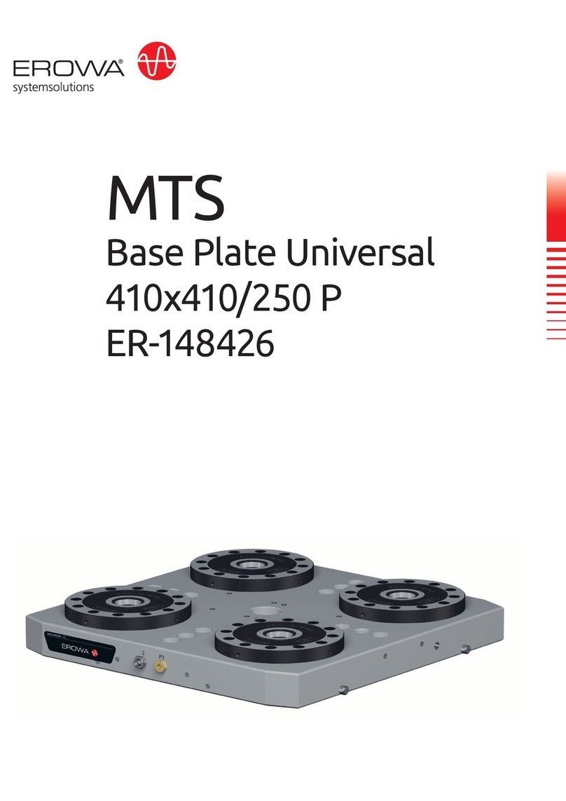
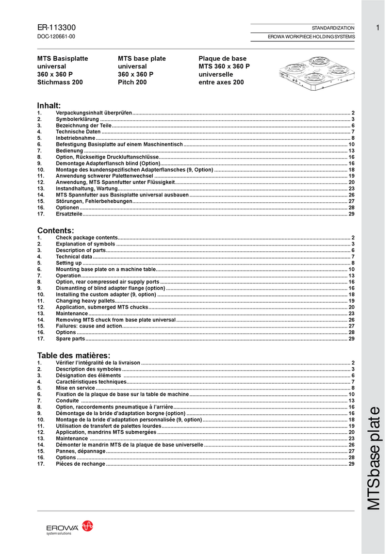
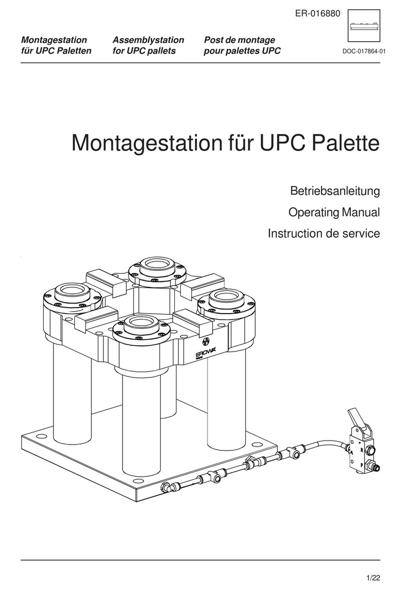
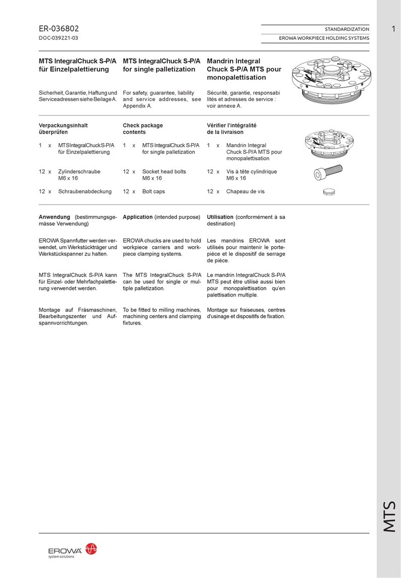
  9. erowa PM85 Multi User manual

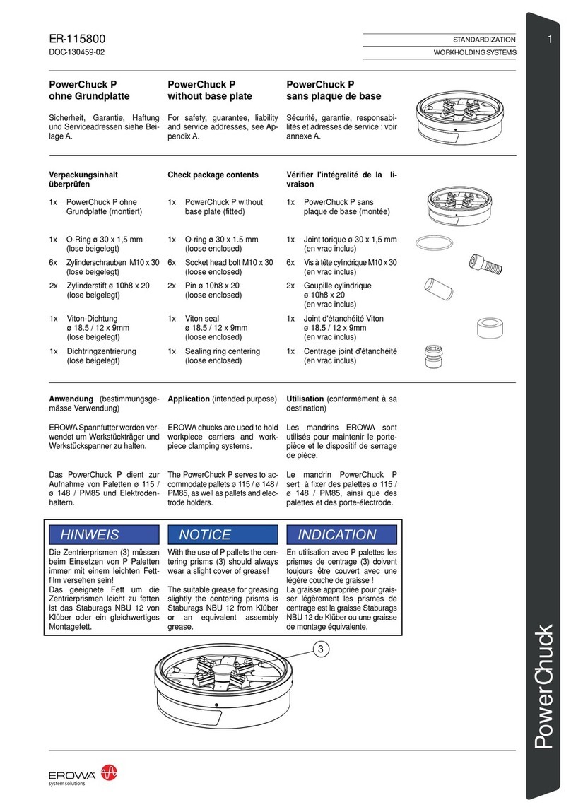
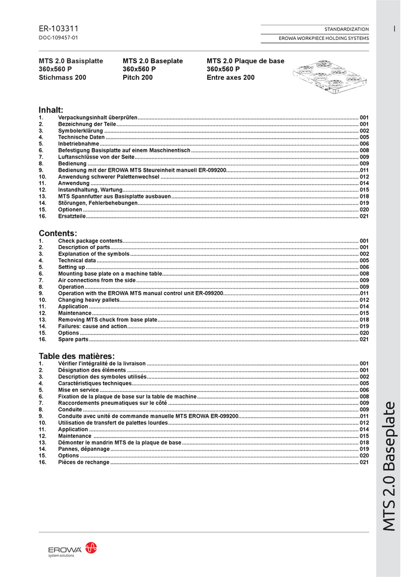
erowa PM85 Multi User manual

ER-060530
ER-062138
1
DOC-084657-00
PM Tooling PM Tooling Outillage PM
Ausrichtdorn PM85 Multi
Sicherheit, Garantie, Haftung
und Serviceadressen siehe Bei-
lage A.
Verpackungsinhalt
überprüfen
1 x Ausrichtdorn
1 x Gewindescheibe
M32 x 1.5
1 x Gewindescheibe
M58 x 1
1 x AusrichtanschPM85 
Multi
4 x Zylinderschraube
M10 x 25
1 x Sechskantschraube
M8 x 30
1 x Steckschlüssel
1 x Sechskantestiftschlüs-
sel SW 4
HINWEIS
Der Ausrichtdorn ist ein sehr
genaues Messmittel und ist mit
entsprechender Vorsicht und
Sauberkeit zu behandeln. Sollten
Spuren von unsach- gemässem
Einsatz, Schlägen oder einer
Nachbearbeitung ersichtlich sein,
so erlöschen jegliche Garantiean-
sprüche.
Positioning pin PM85 Multi
For safety, guarantee, liability
and service addresses, see Ap-
pendix A.
Check package
contents
1 x Positioning pin
1 x Threaded washer
M32 x 1.5
1 x Threaded washer
M58 x 1
1 x AlignmentangePM85
Multi
4 x Socket head bolt
M10 x 25
1 x Hex head screw
M8 x 30
1 x Socket wrench
1 x Hexagon key SW 4
ADVICE
The Positioning pin is a very
accurate measuring instrument
and must be treated with the
appropriate cleanness. If the
alignment pallet shows any signs
of improper handling, hits or any
subsequent machining, this shall
preclude any claims to indemni-
cationundergurantee.
Tasseau de positionnement
PM85 Multi
Sécurité, garantie, responsabili-
tés et adresses de service : voir
annexe A.
Vérier l'intégralité de la
livraison
1 x Tasseau de
positionnement
1 x Rondelleletée
M32 x 1.5
1 x Rondelleletée
M58 x 1
1 x Flasque de positionne-
ment PM85 Multi
4 x Vis à tête cylindrique
M10 x 25
1 x Vis à tête hexagonale
M8 x 30
1 x Clé mâle droite
1 x Clé mâle à six pans
cote sur plats 4
INDICATION
Le tasseau de positionnement
constitue un moyen de mesure
particulièrement précis. Aus-
si doitelle être traitée avec les
précautions d'usage, et être
maintenue dans un parfait état
de propreté. La présence de
traces d'utilisation non conforme
aux règles de l'art, de traces de
chocs ou de retouches entraîne
l'exclusion de toute garantie.
HINTERLEGT
HINTERLEGT
ER-060530
ER-062138
2
DOC-084657-00
PM Tooling PM Tooling Outillage PM
Steht für eine unmittelbar drohende Ge-
fahr, die zu schweren, irreversiblen Kör-
perverletzungen oder zum Tod führt.
Steht für eine möglicherweise gefährliche
Situation, die zu schweren Körperverlet-
zungen führen können.
Steht für eine möglicherweise gefährliche
Situation, die zu leichten Körperverlet-
zungen führen könnte.
Steht für eine möglicherweise schädliche
Situation, bei der das Produkt oder eine
Sache in seiner Umgebung beschädigt
werden könnte.
Steht für Anwendungshinweise und
andere nützliche Informationen.
GEFAHR
WARNUNG
VORSICHT
HINWEIS
WICHTIG
Symbolerklärung
Das EROWA Produkt wurde nach den all-
gemein anerkannten Regeln der Technik
und dem aktuellen Stand von Wissen-
schaft und Technik gefertigt. Dennoch ge-
hen von Maschinen Risiken aus, die sich
konstruktiv nicht vermeiden lassen. Um
dem mit dem EROWA Produkt arbeiten-
den Personal ausreichend Sicherheit zu
gewährleisten, werden zusätzlich Sicher-
heitshinweise gegeben. Nur wenn diese
beachtet werden, ist hinreichende Si-
cherheit beim Umgang mit dem EROWA
Produkt gewährleistet. Bestimmte Text-
stellen sind besonders hervorgehoben.
Die so gekennzeichneten Stellen haben
folgende Bedeutung:
Highlights an immediate thread of danger
that will cause serious, irreversible physi-
cal injury or death.
Highlights a possible dangerous situation
that could cause serious physical injury.
Highlights a possible dangerous situation
that could cause minor physical injury.
Highlights a possible harmful situation in
which the product or an object in the vicin-
ity could be damaged.
Highlights information on usage and other
useful information.
Explanation of the symbols
The EROWA Product has been manufac-
tured according to the generally recog-
nized rules of technology and the state of
the art of science and technology. Even
so, machines involve risks which cannot
be avoided by means of design and con-
struction. In order to provide personnel
working with the EROWAProduct with ad-
equate safety, additional precautions are
provided. Adequate safety at work with
the EROWA Product can only be ensured
if these precautions are being followed.
Certain passages have been marked in a
particular way. The passages marked in
this manner have the following meaning:
DANGER
WARNING
CAUTION
ADVICE
IMPORTANT
Signale un danger qui vous menace
directement et qui provoque de graves
blessures corporelles ou la mort.
Signale une situation potentiellement
dangereuse susceptible de provoquer de
graves blessures corporelles.
Signale une situation potentiellement
dangereuse susceptible de provoquer
des blessures corporelles légères.
Signale une situation potentiellement
néfaste dans laquelle le produit ou un
objet placé à proximité de lui risque d’être
endommagé.
Signale des consignes d’utilisation et
d’autres informations utiles.
Description des symboles utilisés
Le Produit EROWA a été conçu en fonc-
tion des règles techniques généralement
admises et de l’état actuel des connais-
sances scientifiques et techniques. Il
n’en reste pas moins que toute machine
présente nécessairement des risques qui
ne peuvent pas être entièrement éliminés
par la seule approche conceptuelle. D’où
la prescription de consignes de sécu-
rité spécifiques pour assurer une sécurité
maximale au personnel travaillant sur le
Produit EROWA. Seule l’observation de
ces consignes de sécurité permet d’assu-
rer une sécurité suffisante aux personnes
dans leurs rapports avec le Produit ERO-
WA. Certains passages ont été mis en évi-
dence. Ils ont les significations suivantes :
DANGER
AVERTISSEMENT
ATTENTION
INDICATION
IMPORTANT
ER-060530
ER-062138
3
DOC-084657-00
PM Tooling PM Tooling Outillage PM
Bezeichnung der Teile
Ausrichtdorn (A)
B) Messäche(4x)
C) 1/2 IST-Mass zwischen
 Messächen
D) Referenzmarke
Description of parts
Positioning pin (A)
B) Measuringsurface(4x)
C) Actual half distance
between measuring surfaces
D) Reference mark
Désignation des éléments
Tasseau de positionnement (A)
B) Surfacedemesure(4x)
C) Coteeffective(1/2)entre
surfaces de mesure
D) Marque de référence
D
B
C
A
ER-060530
ER-062138
4
DOC-084657-00
PM Tooling PM Tooling Outillage PM
Ausrichtansch (E)
F) Schraube(2x)zumEinstel-
len der seitlichen Position
des Positionierrings PM85
G) Befestigungsbohrung
 ø10.3(4x)
H) Winkeleinstellschraube
 (2x)
I) Schraube zum Ziehen/Stos-
sen des Positionierrings
HINWEIS
Zur Montage des Ausrichtflan-
sches können die gleichen Be-
festigungsbohrungen verwendet
werden, welche für das Spann-
futter PM85 Multi (ER-048580)
nötig sind.
Alignment ange (E)
F) Bolt(2x)fortheadjustment
of the lateral position of the
PM85 positioning ring
G) Attachment borehole
 ø10.3(4x)
H) Angle-adjustment bolt
 (2x)
I) Bolt for pushing/pulling the
positioning ring
ADVICE
To fit the alignment flange, you
can use the same attachment
boreholes, which are necessary
for the Chuck PM85 Multi (ER-
048580).
Flasque de positionnement (E)
F) Vis(2x)pourlepositionne-
ment latéral de la bague de
positionnement PM85
G)Perçagedexation
 ø10.3(4x)
H) Vis de positionnement
 angulaire(2x)
I) Vis pour déplacer la bague de
positionnement vers l'avant /
vers l'arrière
INDICATION
Pour le montage du flasque de
positionnement, on peut utiliser
les mêmes perçages de fixation
que celles prévues pour le man-
drinPM85Multi(ER-048580).
F
G
E
H
I
ø 10.3 (4 x)
ER-060530
ER-062138
5
DOC-084657-00
PM Tooling PM Tooling Outillage PM
Technische Daten
Repetiergenauigkeit:
Anwendung:
DerAusrichtdorn PM85 Multi wird
in Kombination mit der Ausrichts-
matrize(z.BER-047905PM128,
Option) verwendet.
Diese Elemente dienen zum ge-
nauen Ausrichten der Unter- und
Oberstempelspanfutter PM85
Multi(ER-048580)zumMatrizen-
spannfutter.
Einsatzgebiet: Pulverpressen
Inbetriebnahme
Beispiel: Ausrichten des
ER-048580 Spannfutters
PM85 Multi (Unterstempel)
1.
(Bild1)
Positionierring PM85 (K) und
Montagefläche in der Maschine
sauber reinigen. Positionierring
(K) vorsichtig auf der Montage-
flächeplazieren.Aussparung(J)
muss auf der Referenzseite des
Spannfutters liegen. Acht M6 x
14 Schrauben (L) und Spann-
scheiben(M)einschraubenund
nur leicht anziehen.
HINWEIS
Die Komponenten K, L, M sind
im Lieferumfang des Spannfut-
ters PM85 Multi enthalten.
Technical data
Repeatability:
Application:
The alignment pin PM85 Multi
is used in combination with the
alignment die plate (e.g., ER-
047905PM128,option).
These items are used for precise
alignment of the upper and lower
punch chucks PM85 Multi (ER-
048580) to the die plate chuck.
Application: Powder presses
ER-047905
Setting up
Example: Alignment of
ER-048580 chuck PM85 Multi
bottom punch
1.
(Diagram1)
Clean positioning ring PM85
(K)andmountingsurfaceinthe
machine. Place positioning ring
(K) carefully on the mounting
surface.Recess(J)mustbeon
the reference side of the chuck.
InserteightM6 x14 screws(L)
and spring washers (M) and
tighten only slightly.
ADVICE
The components K, L, M are
included in the chuck PM85
Multi.
Caractéristiques techniques
Précision de répétabilité :
Utilisation :
Le tasseau de positionnement
PM85 Multi est utilisé en combi-
naison avec la matrice de posi-
tionnement(par ex.ER-047905
PM128, option).
Ces éléments servent au posi-
tionnement précis des mandrins
de poinçons inférieurs et supé-
rieurs PM85 Multi (ER-048580)
par rapport au mandrin à matrice.
Domaine d'application : Presses
à moulage de poudre
Mise en service
Exemple : Positionnement du
mandrin ER-048580 du poin-
çon inférieur PM85 Multi
1.
(gure1)
Nettoyer soigneusement la bague
de positionnement PM85 (K)
et la surface de montage de la
machine. Placer la bague de
positionnement(K)avecprécau-
tion sur la surface de montage.
L'emplacement(J)doitsetrouver
sur le côté de référence du man-
drin. Visser huit vis M6 x 14(L)
avecrondelles(M) etlesserrer
légèrement.
INDICATION
Les éléments K, L, M sont
fournis avec le mandrin PM85
Multi.
K
J
L
M
1
0,002 mm
ER-060530
ER-062138
6
DOC-084657-00
PM Tooling PM Tooling Outillage PM
2.
(Bild2)
Ausrichtansch (E) anbringen.
Vier M10 x 25 Schrauben (N)
montieren. Schrauben nicht an-
ziehen, Ausrichtansch soll frei
verschiebbar sein.
3.
(Bild3)
Gewindescheibe M58 x 1 (O)
inPositionierring (K)einschrau-
ben.
4.
(Bild4)
Gewindescheibe M32 x 1.5
(P) in Ausrichtdorn PM85 (A)
schrauben und festziehen.
5.
(Bild5)
Ausrichtdorn unter Berücksich-
tigung der Referenzmarken (D)
vorsichtig auf den Positionier-
ring (K) setzen. Die Befesti-
gung des Ausrichtdorns erfolgt
mit Schraube M8 x 30 (X) und
Steckschlüssel. Schraube satt,
aber kontrolliert, anziehen.
2.
(Diagram2)
Fit alignment ange (E). Insert
four M10 x 25 screws (N). Do
not tighten the screws, alignment
angeshouldbefreelymovable.
3.
(Diagram3)
Screw threaded washer M58 x 1
(O)intopositioningring(K).
5.
(Diagram5)
Observing the reference marks
(D), carefully place alignment
pin on the positioning ring (K).
Fasten the alignment pin with
M8 x 30 screw (X) and socket
wrench. Tighten screw fully, but
do not overtighten.
2.
(gure2)
Monterleasquedepositionne-
ment(E).Monterquatrevis
M10x25(N).Nepasserrerles
vis,leasque d'alignementdoit
pouvoir bouger librement.
3.
(figure3)
Visser la rondelle filetée M58 x 1
(O)danslabaguedepositionne-
ment(K).
4.
(figure4)
Visser la rondelle filetée
M32 x 1.5 (P) dans le tasseau
de positionnement PM85 (A) et
la serrer.
5.
(figure5)
Placer avec précaution le tas-
seau de positionnement sur la
bague de positionnement (K)
en tenant compte des repères
deréférence(D). Lafixationdu
tasseau de positionnement est
effectuée avec la vis M8 x 30
(X) et une clé à pipe. Serrer la
vis fermement, mais de manière
contrôlée.
4.
(Diagram4)
Screw M32 x 1.5 threaded
washer (P) into alignment pin
PM85(A)andtighten.
3
2
OK
4
P
A
5
D
K
X
E
N
ER-060530
ER-062138
7
DOC-084657-00
PM Tooling PM Tooling Outillage PM
6.
(Bild6)
Acht Schrauben M6 (L) lösen,
so dass der Positionierring von
Hand verschiebbar ist. Danach
mit Ausrichtdorn vorsichtig nach
oben durch die Öffnung des fest
montierten Matrizenspannfut-
ters (Q) fahren. Dabei Position
des Ausrichtdorns kontrollieren
und bei Bedarf von Hand korri-
gieren.
7.
(Bild7)
Ausrichtmatrize (R) unter Be-
rücksichtigung der Referenz-
marken(D)vorsichtigindasMa-
trizenspannfutter (Q) einspan-
nen. Dazu Matrizenspannfutter
pneumatisch betätigen (min. 6
bar), Ausrichtmatrize einsetzen
und Spannfutter schliessen.
8.
(Bild8)
Mit Ausrichtdorn auf die ge-
wünschte Höhe fahren. Wert an
Messuhren (U1, U2) ablesen
und Ausrichtdorn von Hand grob
ausrichten. Vier Schrauben (L)
über Kreuz leicht anziehen. Aus-
richtflansch (E) zentrieren und
vierSchrauben(N)festziehen.
HINWEIS
Die Berechnung der Einstell-
masse sowie das Voreinstellen
der Ausrichtmatrize entnehmen
Sie bitte der Betriebsanleitung
der Ausrichtmatrize (z.B: ER-
047905).
6.
(Diagram6)
Loosen eight M6 screws (L) so
that the positioning ring can be
moved by hand. Then carefully
move with the alignment pin up
through the opening of the fixed
die plate chuck (Q). Check the
position of the alignment pin and
correct by hand if necessary.
7.
(Diagram7)
Carefully clamp the alignment
die plate (R) in the die plate
chuck (Q), while observing the
reference marks (D). To do so,
operate the pneumatic die pla-
techuck(min.6bar),insertthe
alignment die plate and close
the chuck.
8.
(Diagram8)
Move to the desired height using
the alignment pin. Read off
the values on the dial gauges
(U1, U2) and roughly align the
alignment pin by hand. Slightly
tighten the four screws (L) in a
crosswise pattern. Center the
alignmentflange(E)andtighten
thefourscrews(N).
ADVICE
For the calculation of the set-
ting dimensions and presetting
the alignment die plate, please
refer to the instruction manual
ofthe alignmentdieplate (e.g.,
ER-047905).
6.
(figure6)
DesserrerleshuitvisM6(L)de
sorte que la bague de position-
nement puisse être déplacée à
la main. Ensuite, passer le tas-
seau de positionnement avec
précaution vers le haut à travers
l'orificedumandrinàmatrice(Q)
monté en fixe. Ce faisant, con-
trôler la position du tasseau de
positionnement et la corriger à la
main le cas échéant.
7.
(gure7)
Serrer avec précaution la ma-
trice de positionnement (R)
dans le mandrin à matrice (Q)
en tenant compte des repères
de référence (D). A cet effet,
actionner pneumatiquement le
mandrin à matrice (min. 6 bar),
insérer le tasseau de positionne-
ment et fermer le mandrin.
8.
(figure8)
Déplacer le tasseau de position-
nement sur la hauteur souhai-
tée. Relever la valeur sur les
comparateurs (U1, U2) et ali-
gner le tasseau de positionne-
ment grossièrement à la main.
Serrer légèrement les quatre vis
(L) en croix. Centrer le flasque
d'alignement (E) et serrer les
quatrevis(N).
INDICATION
Le calcul des dimensions de ré-
glage ainsi que le préréglage de
la matrice de positionnement fig-
urent dans le manuel d'utilisation
de la matrice de positionnement
(parex.:ER-047905).
7
R
D
8
6
QL
DQ
U2 U1
E
N
L
ER-060530
ER-062138
8
DOC-084657-00
PM Tooling PM Tooling Outillage PM
Nach Beendigung des Aus-
richtvorgangs Ausrichtdorn (A),
GewindescheibeM58x1(O)und
Ausrichtansch(E)entfernen.
10.
(Bild10)
Sofern möglich, sämtliche
Schrauben(L)imeingefahrenen
Zustand vorsichtig festziehen.
Somit können allfällige Verän-
derungen an den Messuhren
direkt abgelesen und korrigiert
werden.
Ansonsten mit Ausrichtdorn in
Ausgangsposition fahren und
Befestigungsschrauben(L)fest-
ziehen.Zur Kontrolle noch ein-
mal in Ausrichtmatrize einfahren
und Werte kontrollieren.
Wenn Werte an Messuhren kor-
rekt sind, in Ausgangsposition
fahren.
Bei Abweichungen Befesti-
gungsschrauben(L)etwaslösen
und Ausrichtvorgang fortsetzen.
HINWEIS
Die Befestigungsschrauben (L)
des Positionierringes müssen
nach dem Ausrichten mit 14 Nm
festgezogen sein.
9.
(Bild9)
Durch Drehen an den Einstell-
schrauben (H) kann der Positi-
onierring im Winkel ausgerichtet
werden. Die seitliche Positionie-
rung erfolgt über die Schrauben
(F). Mit der Schraube (I) kann
der Positionierring nach hinten
oder vorne verschoben werden.
Position des Positionierrings
korrigieren, bis der gewünschte
Wert erreicht ist.
HINWEIS
Endposition: Grosser Zeiger auf
0, kleiner Zeiger gemäss Be-
rechnung.
After the positioning process has
been completed, remove positio-
ningpin(A),threadedwasher
M58x1(O)andalignmentange
(E).
10.
(Diagram10)
If possible, carefully tighten all
the screws (L) in the retracted
state. This allows you to read
off any changes from the dial
gauges and to correct them.
Otherwise, move with alignment
pin to the initial position and
tightenthefasteningscrews(L).
Move again into alignment die
plate and check the values.
If the values on the gauges
are correct, move to the initial
position.
In case of deviations, slightly
loosen the fastening screws
(L) and continue the alignment
process.
ADVICE
After the positioning ring has
been aligned, tighten the attach-
mentbolts(L)to14 Nm.
9.
(Diagram9)
Turnadjustmentbolts(H)toad-
just the positioning ring’s angle.
Position the chuck laterally with
bolts(F).Usebolt(I)topushor
pull the positioning ring to the
rear or to the front.
Correct the position of the po-
sitioning ring until you have
reached the desired value.
ADVICE
End position: Large pointer to 0,
small pointer as calculated.
Une fois la procédure de posi-
tionnement terminée, retirer le
tausseaudepositionnement(A),
larondelleletéeM58x1(O)et
leasquedepositionnement(E).
10.
(gure10)
Dans la mesure du possible,
serrer avec précaution toutes
les vis (L) à l'état rentré.Ainsi,
les dérives éventuelles peuvent
être relevées directement sur
les comparateurs et corrigées.
Dans le cas contraire, déplacer
le tasseau de positionnement
sur sa position initiale et serrer
lesvisdefixation(L).Pourcon-
trôler, rentrer une nouvelle fois
la matrice de positionnement et
contrôler les valeurs.
Si les valeurs des comparateurs
sont correctes, approcher la po-
sition initiale.
En cas de divergences, desser-
rer légèrement les vis de fixation
(L) et poursuivre le processus
d'alignement.
INDICATION
Après alignement de la bague
de positionnement, serrer les vis
defixation(L)à14 Nm.
9.
(figure9)
Le fait de tourner les vis de ré-
glage (H) permet le positionne-
ment angulaire de la bague de
positionnement. Le positionne-
ment latéral se fait avec les vis
(F).Lavis(I)permetdedéplacer
la bague de positionnement vers
l'arrière ou vers l'avant.
Corriger la bague de positionne-
ment jusqu'à obtenir les valeurs
souhaitées.
INDICATION
Position finale : grande aiguille
sur 0, petite aiguille selon le
calcul.
10
9
H
I
HF
L
A
E
ER-060530
ER-062138
9
DOC-084657-00
PM Tooling PM Tooling Outillage PM
HINWEIS
Die weitere Montage und Inbe-
triebnahme des Spannfutters
(S)entnehmenSiebittederBe-
triebsanleitung des Spannfutters
PM85Multi(ER-048580).
(Bild12)
Nach Beendigung des Ausricht-
vorgangs Matrizenspannfutter
betätigen und Ausrichtmatrize
(R)entfernen.
Das System ist nun betriebs-
bereit.
12.
Oberstempelspannfutter
ausrichten
HINWEIS
Der Ausrichtvorgang für das
Unter- sowie das Oberstempel-
spannfutter sind nahezu iden-
tisch.
Unterschied: Die Ausrichtmat-
rize muss vor dem Einfahren
des Ausrichtdorns im Matrizen-
spannfutter gespannt werden.
11.
(Bild11)
Nach erfolgter Montage des
Spanfutters PM85, Spannfutter
pneumatisch betätigen (min. 6
bar) und Ausrichtdorn vorsichtig
einsetzen unter Berücksichti-
gung der Referenzmarken (D).
Spannfutter schliessen. Durch
einfahren in die Ausrichtmatrize
Werte an den Messuhren (U1,
U2) nochmals kontrollieren.
ADVICE
For the furder setting up process
of the chuck (S), please have
a look to the operating manual
of the Chuck PM85 Multi (ER-
048580).
(Diagram12)
After the positioning process
has been completed, operate
chuck for die-plate and remove
positioningdie-plate(R).
The system is now operational.
12.
Aligning the upper punch
chuck
ADVICE
The alignment processes for
the lower and the upper punch
chucks are almost identical.
Difference: The alignment die plate
must be clamped in the die plate
chuck before inserting the align-
ment pin.
11.
(Diagram11)
When the chuck PM85 has been
mounted, operate the chuck
pneumatically (min. 6 bar) and
carefully insert the alignment pin
while observing the reference
marks (D). Close the chuck.
Check again the values on the
dialgauges (U1,U2)while mo-
ving into the alignment die plate.
INDICATION
Pour la suite du montage et de
la mise en service du mandrin
(S), veuillez vous référer aux
instructions de service du man-
drinPM85Multi(ER-048580).
(gure12)
Une fois la procédure de posi-
tionnement terminée, actionner
le mandrin pour matrice et retirer
lamatricedepositionnement(R).
Le système est maintenant prêt
à fonctionner.
12.
Aligner le mandrin du
poinçon supérieur
INDICATION
Les processus d'alignement
pour les mandrins de poinçons
supérieurs et inférieurs sont
presque identiques.
Différence: la matrice de po-
sitionnement doit être serrée
dans le mandrin à matrice avant
la rentrée du tasseau de posi-
tionnement.
11.
(figure11)
Après le montage du mandrin
PM85, actionner pneumatique-
ment le mandrin (min. 6 bar)
et insérer avec précaution le
tasseau de positionnement, en
tenant compte des repères de
référence (D). Fermer le man-
drin. Contrôler une nouvelle fois
les valeurs sur les comparateurs
(U1,U2)enrentrantdanslama-
trice de positionnement.
12
11
D
S
R
ER-060530
ER-062138
10
DOC-084657-00
PM Tooling PM Tooling Outillage PM
Technischer Support
Für Fragen zu dieser Betriebs-
anleitung kontaktieren Sie bitte:
[email protected].
Ersatzteile
ER-015710
Sechskantstiftschlüssel SW4
ER-000975
Zylinderschraube M10 x 25
Beziehen Sie Ersatzteile bei Ih-
rem EROWA Fachhändler.
Wartung und Pege
Ausrichtdorn und Einzelteile
nach Gebrauch sauber reinigen,
gegen Rost schützen und in die
Originalverpackung zurückle-
gen.
Optionen
ER-047905
Ausrichtmatrize PM128
Precise / Multi
ER-059408
AusrichtmatrizePM190Multi
Technical support
For technical support about this
operating instruction, please
contact: [email protected].
Spare parts
ER-015710
Hexagon key SW4
ER-000975
Socket head bolt M10 x 25
Please order spare parts from
your EROWA dealer.
Maintenance
After use, thoroughly clean the
positioning pin and the other
parts, protect it against corro-
sion, and return it to its original
packaging.
Options
ER-047905
Positioning die-plate PM128
Precise / Multi
ER-059408
Positioning die-plate PM190
Multi
Support technique
Pour support technique à cette ins-
truction de service veuillez prendre
contact: [email protected].
Pièces de rechange
ER-015710
Clé mâle à six pans cote sur
plats 4
ER-000975
Vis à tête cylindrique M10 x 25
Commandez les pièces de
rechange chez votre agent
EROWA.
Maintenance
Après utilisation, nettoyer soi-
gneusement le tasseau de posi-
tionnement, la protéger contre
la rouille et la remettre dans son
emballage d’origine.
Options
ER-047905
Matrice de positionnement
PM128 Precise / Multi
ER-059408
Matrice de positionnement
PM190Multi
HINTERLEGT
HINTERLEGT
Beilage A Appendix A Edition 11.2013
Sicherheit, Garantie
und Haftung
Der Hersteller
EROWA AG
Knutwilerstrasse
CH-6233 Büron LU /
Switzerland
Tel. ++41 (0)41-935 11 11
Fax ++41 (0)41-935 12 13
e-mail: [email protected]
www.erowa.com
erklärt hiermit, dass seine Pro-
dukte nach modernsten Ferti-
gungsmethoden hergestellt und
während der Produktion und
als Endprodukt durch unsere
Qualitätssicherung umfassend
geprüft werden.
Die Garantie beträgt 12 Mo-
nate ab Verkaufsdatum. Sie
beschränkt sich auf den Ersatz
von defekten Teilen. Weiterge-
hende Ansprüche sind ausge-
schlossen.
Die Produkte der EROWA AG
müssen unter den, in dieser
Dokumentation genannten Be-
dingungen, eingesetzt und be-
trieben werden. Es dürfen nur
EROWA AG Originalteile (Er-
satz-, Verschleissteile, Nach-
rüstungen) verwendet werden.
Nur unter Einhaltung dieser
Konditionen ist eine Funktion
sichergestellt und eine Gefähr-
dung von Mensch und Maschi-
ne ausgeschlossen.
Trotz aller Sorgfalt kann di-
ese Dokumentation Fehler
aufweisen. Für Folgeschäden
übernimmt die EROWA AG
keine Haftung. Technische Än-
derungen vorbehalten.
Security, guarantee
and liability
Manufacturer
EROWA AG
Knutwilerstrasse
6233 Büron LU /
Switzerland
Tel. +41 (0)41 935 11 11
Fax +41 (0)41 935 12 13
Email: [email protected]
www.erowa.com
hereby confirms that the
company’s products are ma-
nufactured using the latest pro-
duction methods and that they
are subject to extensive quality
checks both during production
and on the end product.
Guarantee is valid for 12 months
from the date of purchase. It is
limited to the replacement of
faulty parts. Further reaching
claims are precluded.
The products of EROWA AG
must be installed and operated
in strict accordance with the
conditions laid down in this do-
cumentation. Only EROWA AG
original parts (spare parts, wear
parts, retrofits) are allowed for
use.
Only strict adherence to these
conditions will ensure proper
working order of the machine
and preclude any danger to
people and to the machine.
Despite all due care, this docu-
mentation may contain errors.
EROWA AG shall not be liable
for any consequential damage.
Technical modifications are re-
served.
Patente:
Diese Produkte sind durch eine
oder mehrere der folgenden
Patente (Anmeldungen) ge-
schützt.
Patents:
These products are protected
by one or more of the following
patents (applications).
US 4,615,688
US 4,621,821
US 5,065,991
US 4,686,768
US 534,527
US 089,017
US Re, 33,249
US 4,934,680
US 4,786,062
US 751,158
US 6,367,814
EU 0 111 092
EU 0 308 370
EU 0 147 531
EU 0 248 116
EU 237 614
EU 90810402.9
EU 90810401.9
EU 91810937.2
CAN 1,210,538
CAN 1,260,968
CAN 1,271,917
Taiwan 47696
Taiwan 55651
Taiwan 47122
Taiwan 61080
Taiwan 42155
Taiwan 80109549
Japan 024414/87
Japan 151430/90
Japan 335221/91
Japan 58-195916
Japan 238990/86
Japan 220264/88
Japan 151429/90
Taiwan 205105
Tochtergesellschaften
Subsidiaries / Filiales
Deutschland
EROWA System Technologien GmbH
Gewerbepark Schwadermühle
Rossendorferstrasse 1
DE-90556 Cadolzburg b. Nbg.
Deutschland
Tel. 09103 7900-0
Fax 09103 7900-10
[email protected]
www.erowa.de
Frankreich
EROWA Distribution France Sàrl
PAE Les Glaisins
12, rue du Bulloz
FR-74940 Annecy-le-Vieux
France
Tel. 4 50 64 03 96
Fax 4 50 64 03 49
[email protected]
www.erowa.com
Italien Italien
EROWA Tecnologie S.r.l. EROWA Tecnologie S.r.l.
Strada Statale 24 km 16,200 Via Leonardo Da Vinci n. 8
IT-10091 Alpignano (TO) IT-31020 Villorba (TV)
Italia Italia
Tel. 011 9664873 Tel. 011 9664873
Fax 011 9664875 Fax -
[email protected] [email protected]
www.erowa.com www.erowa.com
Spanien
EROWA Technology Ibérica S.L.
c/ Avda. Cornellá, 142 70 3a ext.
E-08950 Esplugues de Llobregat - Barcelona
España
Tel. 093 265 51 77
Fax 093 244 03 14
[email protected]
www.erowa.com
Skandinavien
EROWA Technology Scandinavia A/S
Fasanvej 2
DK-5863 Ferritslev Fyn
Denmark
Tel. 65 98 26 00
Fax 65 98 26 06
[email protected]
www.erowa.com
Osteuropa
EROWA Technology Sp. z o.o.
Eastern Europe
ul. Spółdzielcza 37-39
55-080 Kąty Wrocławskie
Poland
Tel. 71 363 5650
Fax 71 363 4970
[email protected]
www.erowa.com
Indien
EROWA Technology (India) Private Limited
No: 6-3-1191/6, Brij Tarang Building
Unit No-3F, 3rd Floor, Greenlands, Begumpet,
Hyderabad 500 016 (Andhra Pradesh)
India
Tel. 040 4013 3639
Fax 040 4013 3630
[email protected]
www.erowa.com
USA
EROWA Technology, Inc.
North American Headquarters
2535 South Clearbrook Drive
Arlington Heights, IL 60005
USA
Tel. 847 290 0295
Fax 847 290 0298
e-mail: info@erowa.com
www.erowa.com
China
EROWA Technology (Shanghai) Co., Ltd.
G/F, No. 24 Factory Building House
69 Gui Qing Road (Caohejing Hi-tech Park)
Shanghai 200233, PRC
China
Tel. 021 6485 5028
Fax 021 6485 0119
[email protected]
www.erowa.cn
Singapur
EROWA (South East Asia) Pte. Ltd.
CSE Global Building
No.2 Ubi View, #03-03
Singapore 408556
Singapore
Tel. 65 6547 4339
Fax 65 6547 4249
[email protected]
www.erowa.com
Japan
EROWA Nippon Ltd.
Sasano Bldg.
2-6-4 Shiba Daimon, Minato-ku
105-0012 Tokyo
Japan
Tel. 03 3437 0331
Fax 03 3437 0353
[email protected]
www.erowa.co.jp
Annexe A
Sécurité, garantie
et responsabilité
Le fabricant
EROWA AG
Knutwilerstrasse
CH-6233 Büron LU /
Suisse
Tél. ++41 (0)41-935 11 11
Fax ++41 (0)41-935 12 13
e-mail: [email protected]
www.erowa.com
déclare par la présente que ses
produits ont été fabriqués con-
formément aux méthodes de
fabrication les plus modernes,
et qu’ils ont été contrôlés de
manière approfondie par no-
tre service d’assurance qualité
pendant la fabrication et en tant
que produit fini.
La durée de la garantie est de
12 mois à compter de la date de
la vente. Elle se limite au rem-
placement des pièces défec-
tueuses. Toute autre forme de
recours au titre de la garantie
est exclue.
L’utilisation et l’exploitation des
produits EROWA AG doivent
être conformes aux spécifica-
tions du présent document.
Seules des pièces d’origine
EROWA AG doivent être uti-
lisées (pièces de rechange,
d’usure, de rééquipement).
L’observation de ce dernier est
indispensable pour assurer un
fonctionnement fiable et préve-
nir les risques corporels et ma-
tériels.
Malgré les soins apportés à sa
rédaction, le présent document
peut présenter des erreurs.
EROWA AG décline toute re-
sponsabilité résultant de telles
erreurs. EROWA AG se réserve
également le droit de procéder
à des modifications d’ordre
technique.
Brevets :
Ces produits sont protégés
par les brevets (ou dépôts de
brevet) suivants :

This manual suits for next models

2

Other erowa Industrial Equipment manuals

erowa ER-148426 User manual

erowa

erowa ER-148426 User manual

erowa ER-113300 User manual

erowa

erowa ER-113300 User manual

erowa ER-016880 User manual

erowa

erowa ER-016880 User manual

erowa MTS IntegralChuck S-P/A User manual

erowa

erowa MTS IntegralChuck S-P/A User manual

erowa MTS User manual

erowa

erowa MTS User manual

erowa PowerChuck P without base plate User manual

erowa

erowa PowerChuck P without base plate User manual

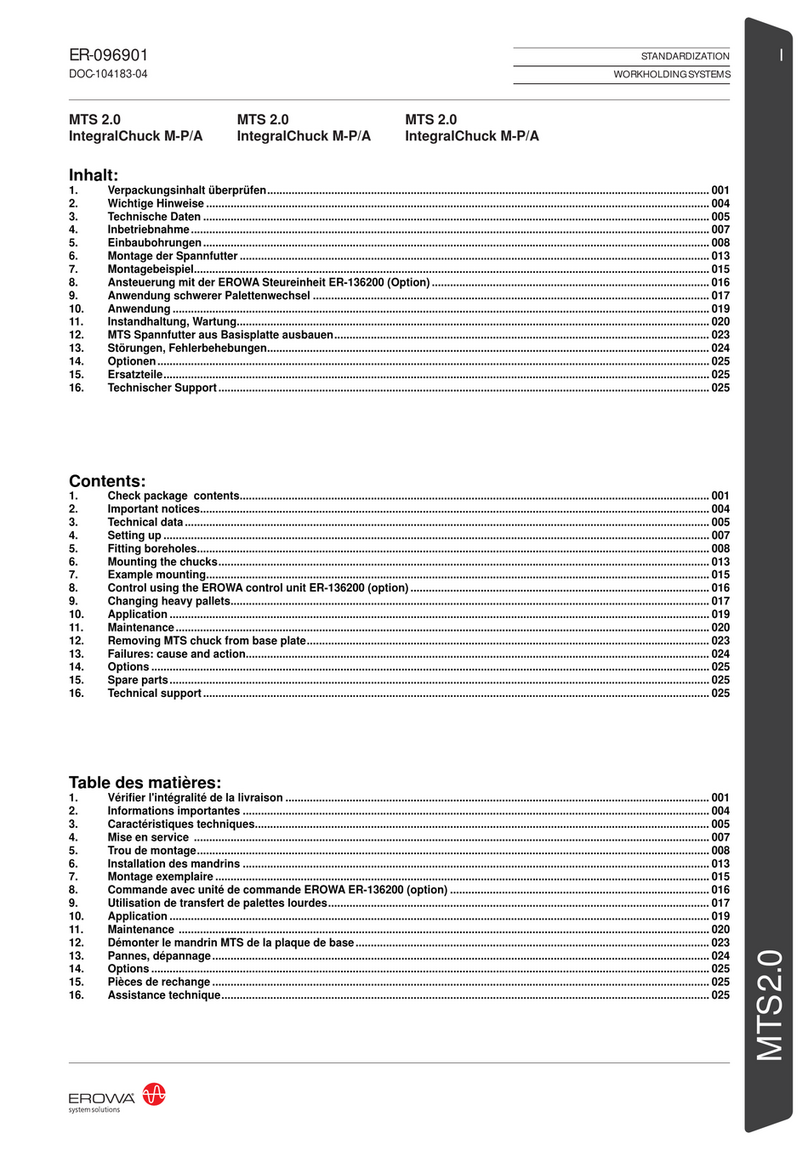
erowa MTS 2.0 IntegralChuck M-P/A User manual

erowa

erowa MTS 2.0 IntegralChuck M-P/A User manual

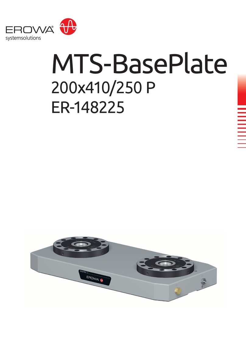
erowa MTS-BasePlate 200x410/250 P User manual

erowa

erowa MTS-BasePlate 200x410/250 P User manual

erowa MTS 2.0 User manual

erowa

erowa MTS 2.0 User manual

erowa ER-103311 User manual

erowa

erowa ER-103311 User manual

erowa PowerChuck P User manual

erowa

erowa PowerChuck P User manual

Popular Industrial Equipment manuals by other brands

PPI SMART ROLL operation & maintenance

PPI

PPI SMART ROLL operation & maintenance

bora PM-1800 user manual

bora

bora PM-1800 user manual

schmersal AZM300B-ST-SD2P Instructions for operation

schmersal

schmersal AZM300B-ST-SD2P Instructions for operation

Charmhigh CHM-T560P4 user manual

Charmhigh

Charmhigh CHM-T560P4 user manual

Endress+Hauser Hart Proline Promag P 500 Special Documentation

Endress+Hauser

Endress+Hauser Hart Proline Promag P 500 Special Documentation

ABB DDA 200 A AE quick start guide

ABB

ABB DDA 200 A AE quick start guide

Siemens SIRIUS 3RA242 8X 3 1 Series operating instructions

Siemens

Siemens SIRIUS 3RA242 8X 3 1 Series operating instructions

PairGain HiGain HLU-D41 manual

PairGain

PairGain HiGain HLU-D41 manual

ESO CRIRES user manual

ESO

ESO CRIRES user manual

Nordson EPC-15 instruction sheet

Nordson

Nordson EPC-15 instruction sheet

RINGSPANN FRS Series Installation, Lubrication, Maintenance Instructions

RINGSPANN

RINGSPANN FRS Series Installation, Lubrication, Maintenance Instructions

Midwest Specialties FlexArm A-32 Installation & operation manual

Midwest Specialties

Midwest Specialties FlexArm A-32 Installation & operation manual

Siemens SITRANS SCM IQ Compact operating instructions

Siemens

Siemens SITRANS SCM IQ Compact operating instructions

Parker Siemens APOGEE P1 manual

Parker

Parker Siemens APOGEE P1 manual

Siemens Simotics operating instructions

Siemens

Siemens Simotics operating instructions

ABB DressPack product manual

ABB

ABB DressPack product manual

STS LABEL APPLICATOR STS808-3 user manual

STS

STS LABEL APPLICATOR STS808-3 user manual

Diamond Products CVG1 Operator's manual

Diamond Products

Diamond Products CVG1 Operator's manual

manuals.online logo
manuals.online logoBrands
  • About & Mission
  • Contact us
  • Privacy Policy
  • Terms and Conditions

Copyright 2025 Manuals.Online. All Rights Reserved.