manuals.online logo
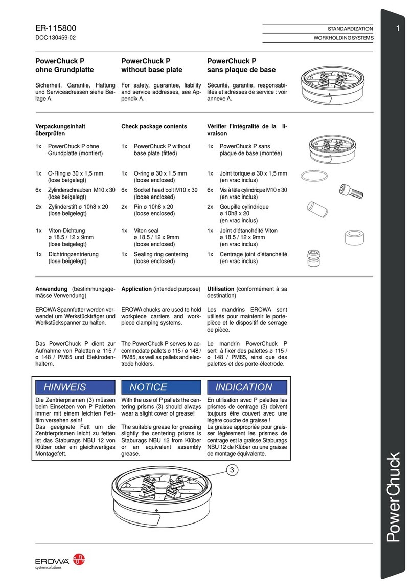
Brands
  1. Home
  2. •
  3. Brands
  4. •
  5. erowa
  6. •
  7. Industrial Equipment
  8. •
  9. erowa MTS 2.0 IntegralChuck M-P/A User manual

erowa MTS 2.0 IntegralChuck M-P/A User manual

I
STANDARDIZATION
WORKHOLDINGSYSTEMS
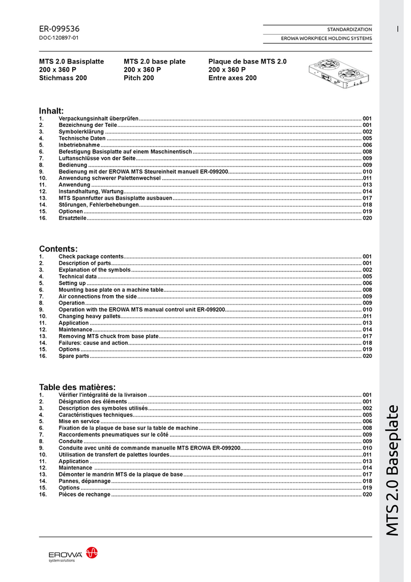
MTS 2.0
ER-096901
MTS 2.0
IntegralChuck M-P/A
Inhalt:
1. Verpackungsinhalt überprüfen................................................................................................................................................. 001
2. Wichtige Hinweise..................................................................................................................................................................... 004
3. Technische Daten...................................................................................................................................................................... 005
4. Inbetriebnahme.......................................................................................................................................................................... 007
5. Einbaubohrungen...................................................................................................................................................................... 008
6. Montage der Spannfutter..........................................................................................................................................................013
7. Montagebeispiel......................................................................................................................................................................... 015
8. Ansteuerung mit der EROWA Steureinheit ER-136200 (Option)........................................................................................... 016
9. Anwendung schwerer Palettenwechsel .................................................................................................................................. 017
10. Anwendung................................................................................................................................................................................ 019
11. Instandhaltung, Wartung........................................................................................................................................................... 020
12. MTS Spannfutter aus Basisplatte ausbauen........................................................................................................................... 023
13. Störungen, Fehlerbehebungen................................................................................................................................................. 024
14. Optionen..................................................................................................................................................................................... 025
15. Ersatzteile................................................................................................................................................................................... 025
16. Technischer Support................................................................................................................................................................. 025
MTS 2.0
IntegralChuck M-P/A
Contents:
1. Check package contents.......................................................................................................................................................... 001
2. Important notices....................................................................................................................................................................... 004
3. Technical data............................................................................................................................................................................ 005
4. Setting up................................................................................................................................................................................... 007
5. Fitting boreholes........................................................................................................................................................................ 008
6. Mounting the chucks................................................................................................................................................................. 013
7. Example mounting..................................................................................................................................................................... 015
8. Control using the EROWA control unit ER-136200 (option).................................................................................................. 016
9. Changing heavy pallets............................................................................................................................................................. 017
10. Application................................................................................................................................................................................. 019
11. Maintenance............................................................................................................................................................................... 020
12. Removing MTS chuck from base plate.................................................................................................................................... 023
13. Failures: cause and action........................................................................................................................................................ 024
14. Options....................................................................................................................................................................................... 025
15. Spare parts................................................................................................................................................................................. 025
16. Technical support...................................................................................................................................................................... 025
DOC-104183-04
MTS 2.0
IntegralChuck M-P/A
Table des matières:
1. Vérifier l'intégralité de la livraison ........................................................................................................................................... 001
2. Informations importantes ......................................................................................................................................................... 004
3. Caractéristiques techniques..................................................................................................................................................... 005
4. Mise en service ......................................................................................................................................................................... 007
5. Trou de montage........................................................................................................................................................................008
6. Installation des mandrins ......................................................................................................................................................... 013
7. Montage exemplaire.................................................................................................................................................................. 015
8. Commande avec unité de commande EROWA ER-136200 (option)..................................................................................... 016
9. Utilisation de transfert de palettes lourdes............................................................................................................................. 017
10. Application................................................................................................................................................................................. 019
11. Maintenance .............................................................................................................................................................................. 020
12. Démonter le mandrin MTS de la plaque de base.................................................................................................................... 023
13. Pannes, dépannage................................................................................................................................................................... 024
14. Options....................................................................................................................................................................................... 025
15. Pièces de rechange...................................................................................................................................................................025
16. Assistance technique................................................................................................................................................................ 025
II STANDARDIZATION
WORKHOLDINGSYSTEMS ER-096901
DOC-104183-04
001
STANDARDIZATION
WORKHOLDINGSYSTEMS
MTS 2.0
ER-096901
123
5
6
4
P4 P6
7
5
Sicherheit, Garantie, Haftung
und Serviceadressen siehe Bei-
lage A.
1. Verpackungsinhalt über-
prüfen
Bezeichnung der Teile
MTS 2.0
IntegralChuck M-P/A
1x MTS 2.0 IntegralChuck
M-P/A
12x Zylinderschraube
M6 x 16
12x Verschlussstopfen
Schrauben MTS
1) Deckel
2) Z-Auflagen mit Bohrungen
für Reinigung/Überwa-
chung
3) Bohrung für Befestigungs-
schraube (12 x)
4) Hinweis: Anleitung lesen
5) Zylinderstift für
Verdrehsicherung
6) MTS Verschlusszapfen
7) Serienummer
P4) Position Nachspannen
P6) Position Offenkontrolle
EROWA Spannfutter werden ver-
wendet um Werkstückträger und
Werkstückspanner zu halten.
1x Zylinderstift
m6 ø 6 x 16
For safety, guarantee, liability
and service addresses, see Ap-
pendix A.
1. Check package contents
Description of parts
MTS 2.0
IntegralChuck M-P/A
1x MTS 2.0 IntegralChuck
M-P/A
12x Sealing Cap for MTS
12x Socket head bolt
M6 x 16
1) Cover
2) Z-supports
with boreholes for
cleaning/monitoring
3) Boreholes for attachment-
bolts (12 x)
4) Note: read manual
5) Dowel pin for
anti-rotation device
6) MTS Locking bolt
7) Serial Number
P4) Reclamp position
P6) Position open check
EROWA chucks are used to hold
workpiece carriers and work-
piece clamping systems.
1x Dowel pin
m6 ø 6 x 16
DOC-104183-04
Sécurité, garantie, responsabi-
lités et adresses de service :
voir annexe A.
Désignation des éléments
MTS 2.0
IntegralChuck M-P/A
1) Couvercle
2) Appuis Z
avec perçages pour
nettoyage/surveillance
3) Perçage pour vis de fixa-
tion (12 x)
4) Avis: consulter manuel
5) Goupille cylindrique pour
dispositif anti-torsion
6) MTS Tenon de serrage
7) Nombre de série
P4) Position resserrage
P6) Contrôle position ouvert
1. Vérifier l'intégralité de la
livraison
1x MTS 2.0 IntegralChuck
M-P/A
12x Capuchon pour vis
couvercle MTS
12x Vis à tête cylindrique
M6 x 16
Utilisation (conformément à sa
destination)
Anwendung (bestimmungsge-
mässe Verwendung) Application (intended purpose)
Les mandrins EROWA sont
utilisés pour maintenir le porte-
pièce et le dispositif de serrage
de pièce.
1x Goupille cylindrique
m6 ø 6 x 16
002 STANDARDIZATION
WORKHOLDINGSYSTEMS ER-096901
Steht für eine unmittelbar drohende Ge-
fahr, die zu schweren, irreversiblen Kör-
perverletzungen oder zum Tod führt.
Steht für eine möglicherweise gefährliche
Situation, die zu schweren Körperverlet-
zungen oder zum Tod führen kann.
Steht für eine möglicherweise gefährliche
Situation, die zu geringfügigen oder mäs-
sigen Verletzungen führen kann.
Steht für eine möglicherweise schädliche
Situation, bei der das Produkt oder eine
Sache in seiner Umgebung beschädigt
werden könnte.
Steht fürAnwendungshinweise und ande-
re nützliche Informationen.
GEFAHR
WARNUNG
VORSICHT
HINWEIS
WICHTIG
Das EROWA Produkt wurde nach den all-
gemein anerkannten Regeln der Technik
und dem aktuellen Stand von Wissen-
schaft und Technik gefertigt. Dennoch ge-
hen von Maschinen Risiken aus, die sich
konstruktiv nicht vermeiden lassen. Um
dem mit dem EROWA Produkt arbeiten-
den Personal ausreichend Sicherheit zu
gewährleisten, werden zusätzlich Sicher-
heitshinweise gegeben. Nur wenn diese
beachtet werden, ist hinreichende Sicher-
heit beim Umgang mit dem EROWA Pro-
dukt gewährleistet. Bestimmte Textstellen
sind besonders hervorgehoben. Die so
gekennzeichneten Stellen haben folgen-
de Bedeutung:
Symbolerklärung
Highlights an immediate thread of danger
that will cause serious, irreversible physi-
cal injury or death.
Highlights a possible dangerous situation
that could cause serious physical injury or
death.
Highlights a possible dangerous situation
that could cause minor or moderate injury.
Highlights a possible harmful situation in
which the product or an object in the vicin-
ity could be damaged.
Highlights information on usage and other
useful information.
The EROWA Product has been manufac-
tured according to the generally recog-
nized rules of technology and the state of
the art of science and technology. Even
so, machines involve risks which cannot
be avoided by means of design and con-
struction. In order to provide personnel
working with the EROWA Product with ad-
equate safety, additional precautions are
provided. Adequate safety at work with
the EROWAProduct can only be ensured
if these precautions are being followed.
Certain passages have been marked in a
particular way. The passages marked in
this manner have the following meaning:
DANGER
WARNING
CAUTION
NOTICE
IMPORTANT
Explanation of the symbols
DOC-104183-04
Signale un danger qui vous menace
directement et qui provoque de graves
blessures corporelles ou la mort.
Signale une situation potentiellement
dangereuse pouvant entraîner la mort ou
de graves blessures corporelles.
Signale une situation potentiellement
dangereuse pouvant entraîner des bles-
sures légères ou modérées.
Signale une situation potentiellement
néfaste dans laquelle le produit ou un
objet placé à proximité de lui risque d’être
endommagé.
Signale des consignes d’utilisation et
d’autres informations utiles.
Le Produit EROWA a été conçu en fonc-
tion des règles techniques généralement
admises et de l’état actuel des connais-
sances scientifiques et techniques. Il
n’en reste pas moins que toute machine
présente nécessairement des risques qui
ne peuvent pas être entièrement éliminés
par la seule approche conceptuelle. D’où
la prescription de consignes de sécu-
rité spécifiques pour assurer une sécurité
maximale au personnel travaillant sur le
Produit EROWA. Seule l’observation
de ces consignes de sécurité permet
d’assurer une sécurité suffisante aux per-
sonnes dans leurs rapports avec le Pro-
duit EROWA. Certains passages ont été
mis en évidence. Ils ont les significations
suivantes :
DANGER
AVERTISSEMENT
ATTENTION
INDICATION
IMPORTANT
Description des symboles utilisés
003
STANDARDIZATION
WORKHOLDINGSYSTEMS
MTS 2.0
ER-096901
WARNUNG
Unsachgemässe Bedienung,
fehlerhafte Manipulation oder
fehlerhaftes Material (herun-
terfallen von Teilen, Lärm) kön-
nen zu schweren Körperverlet-
zungen führen.
Der Bediener ist aufgefordert
die vorhandene persönliche
Schutzausrüstung (z.B. Schutz-
brille, Schutzschuhe und Gehör-
schutz) korrekt zu tragen.
GEFAHR
Unvorhersehbare Fehlfunkti-
onen oder fehlerhaftes Material
des Produkts (wegfliegen von
Teilen), können zu schweren
und irreversiblen Körperverlet-
zungen führen.
Die vorhandenen Schutzeinrich-
tungen sind gemäss der Betrieb-
sanleitung (Werkzeugmaschine)
korrekt und konsequent anzu-
wenden.
Schutzeinrichtungen
Persönliche Schutzausrüstung
HINWEIS
Die Auswahl und die Prüfung
über den Einsatz der einzelnen
Schutzausrüstungsgegenstän-
de hat durch den Betreiber zu
erfolgen.
WARNUNG
Maximaler Reinigungsdruck be-
achten.
Zu starkes Abblasen und Lärm
mit der Druckluft vermeiden,
Gehörschutz tragen.
Gegen Augenverletzungen gut
sitzende Schutzbrille tragen
(auch Drittpersonen). Gefähr-
dung durch Versprühen von
Flüssigkeit und wegfliegenden
Spänen, etc.
Müssen Teile beim Abblasen in
der Hand gehalten werden, sind
geeigneteHandschuhe zu tragen.
Arbeiten mit Druckluft
WARNING
Improper operation, erroneous
manipulation or faulty material
(falling parts, noise) can lead to
serious personal injury.
The operator is requested to
properly wear the existing per-
sonal protective equipment
(e.g., goggles, protective shoes,
and hearing protection).
DANGER
Unforeseeable malfunctions or
faulty material of the product
(parts being thrown out) can
cause severe and irreversible
injury.
The existing protection devices
must be used properly and con-
sistently according to the operat-
ing instructions (machine tool).
NOTICE
The operating company is re-
sponsible for the selection and
verification of use of the individ-
ual protection equipment.
Protection devices
Personal protective equipment
WARNING
Be sure to observe the maxi-
mum cleaning pressure.
Avoid excessive blowing and
noise with compressed air, wear
hearing protection.
To avoid eye injuries, wear
properly fitting safety glasses
(including third parties). Risk of
spraying liquid and projection of
chips, etc.
If you must hold any parts in
your hand while blowing them
off, wear suitable gloves.
Working with compressed air
DOC-104183-04
AVERTISSEMENT
Toute utilisation non conforme,
manipulation erronée ou ma-
tériau défectueux (chutes de
pièces, bruit) peut entraîner de
lourdes blessures corporelles.
L’opérateur est prié de porter
correctement les équipements
de protection individuelle ex-
istants (lunettes de sécurité,
chaussures de sécurité, protec-
tion auditive, etc.).
DANGER
Des dysfonctionnements im-
prévisibles ou un matériau dé-
fectueux dans le produit (pièces
qui s’échappent) peuvent en-
traîner des blessures corpo-
relles lourdes et irrémédiables.
Les dispositifs de protection ex-
istants doivent donc être utilisés
systématiquement et conformé-
ment aux instructions de service
(de la machine-outil).
Équipement de protection
individuelle
INDICATION
L’exploitant est responsable de
la sélection et du contrôle des
différents équipements de pro-
tection individuelle.
Dispositifs de protection
AVERTISSEMENT
Observer la pression de netto-
yage maximale.
Éviter un nettoyage par souffla-
ge et bruit à trop forte pression,
porter une protection auditive.
Porter des lunettes de sécurité
bien ajuster pour éviter toute
blessure des yeux (tierces per-
sonnes également). Risque de
pulvérisation de liquides et de
projection de copeaux, etc.
Si le nettoyage exige de tenir
des pièces à la main, porter des
gants appropriés.
Travailler avec de l’air comprimé
004 STANDARDIZATION
WORKHOLDINGSYSTEMS ER-096901
8
WARNUNG
HINWEIS
An MTS Spannfuttern dürfen
keinerlei Veränderungen, wie
z.B. Bohrungen, Überschleifen,
vorgenommen oder andere Fe-
dern oder O-Ringe eingesetzt
werden.
2. Wichtige Hinweise
HINWEIS
Fette und Pasten mit Fest-
schmierstoffen dürfen nicht ver-
wendet werden. Sie können im
Zentrierkonus (8) zu unlösbaren
Verbindungen führen.
Versuchen Sie nie ein MTS
Spannfutter zu zerlegen ohne
über die notwendige Ausbildung
und das richtige Hilfsmaterial zu
verfügen. MTS Spannfutter ste-
hen unter hoher FEDERSPAN-
NUNG.
WARNING
Never attempt to disassemble
an MTS chuck without having
the necessary training and ac-
cessories to do so. MTS chucks
are subjected to high spring ten-
sion at all times.
NOTICE
No mechanical adaptions, such
as additional holes or re-grind-
ing surfaces, are allowed on any
MTS chucks. Never attempt to
insert other springs or O-rings
than specified.
2. Important notices
NOTICE
Do not use any masses or
pastes containing solid lubri-
cants. They may cause the
chucking spigot to be stuck in
the centering taper (8).
DOC-104183-04
AVERTISSEMENT
Ne jamais tenter de démonter
un mandrin MTS sans avoir la
formation et les accessoires
nécessaires pour le faire. Man-
drins MTS sont soumis à la ten-
sion du ressort haute en tout
temps.
INDICATION
Aucune adaptation mécanique,
(trous supplémentaires ou rec-
tification supplémentaire) sont
admis avec les mandrins MTS.
N'essayez jamais d'insérer
d'autres sources où joints to-
rique que celles spécifiées.
2. Informations importantes
INDICATION
L’utilisation de graisses ou de
pâtes contenant des lubrifiants
solides est prohibée car risquant
de provoquer des phénomènes
de métallisation dans le cône de
centrage (8).
005
STANDARDIZATION
WORKHOLDINGSYSTEMS
MTS 2.0
ER-096901
< 0,003 mm
9'000 N (Tol ±10%)
ISO 8573.1
+5° - +70° C
6-10 bar
20'000 N (Tol ±10%)
5-6 bar
1.9 kg
3. Technische Daten
Spannkraft ohne Verwendung
der Nachspannung:
Die angegebene Repetier-
genauigkeit gilt erst bei mini-
mum zwei zueinander montier-
ten MTS Spannfuttern.
Repetiergenauigkeit:
WICHTIG
P2 Öffnen
P3 Reinigen (Netzdruck max)
WICHTIG
Für eine optimale Reinigung/Ab-
blasung des Spannfutters emp-
fehlen wir einen Luftdurchfluss
von 60 Liter/Minute je Spann-
futter.
HINWEIS
Der Reinigungsdruck darf 6 bar
nicht überschreiten, da sonst
beim Einsetzen einer Palette
die O-Ringe am Spannzapfen
weggedrückt werden. Dadurch
werden die O-Ringe beim Auf-
setzen zerstört und die Anwe-
senheitskontrolle funktioniert
nicht mehr richtig.
Automatisierbar: Ja
Überwachung:
Offenkontrolle (P6),
Anwesenheit Palette (P3)
Druckluftqualität Klasse 4:
Wir empfehlen die Luftversor-
gung über eine Wartungseinheit
mit Öl und Wasserabscheider zu
führen.
Betriebstemperatur
Gespannt: Drucklos
Spannkraft mit Nachspannung
max. 6 bar:
Bei rotativen Anwendungen
> 80 U/min. (beispielsweise
Fräs-Dreh-Bearbeitungen) müs-
sen die Spannfutter zwingend
nachgespannt werden.
WICHTIG
Gewicht:
3. Technical data
The abovementioned repeat-
ability only applies when at least
two MTS Chucks have been fit-
ted with reference to each other.
Repeatability:
IMPORTANT
P2 Open
P3 Cleaning (Supply pressure
max)
IMPORTANT
For best cleaning/blow-off of the
chuck, we recommend an air
flow rate of 60 liters/minute for
each chuck.
NOTICE
The cleaning pressure should
not exceed 6 bar, because oth-
erwise the O-rings on the chuck-
ing spigot could be pushed away
when inserting a pallet. This
would damage the O-rings when
placed upon, and the presence
check would no longer function
properly.
Automatable: Yes
Monitoring:
Open check (P6),
pallet present (P3)
Quality of compressed air class 4:
We recommend to feed the air-
supply through a unit with oil and
waterseparator.
Operating temperature
Clamped by depressurization
Clamping power with reclamp-
ing at max. 6 bar:
Clamping power without using
reclamping:
For rotary applications > 80 rpm.
(e.g. milling-turning operations),
the chucks must be reclamped.
IMPORTANT
Weight:
DOC-104183-04
3. Caractéristiques tech-
niques
La précision de répétabilité indi-
quée ne s'applique qu'avec au
moins deux mandrins MTS mon-
tés l'un avec l'autre.
Précision de répétabilité :
IMPORTANT
P2 Ouverture
P3 Nettoyage (Pression du ré-
seau max)
IMPORTANT
Pour un nettoyage/nettoyage à
l’air comprimé optimal du man-
drin, nous recommandons un
débit d’air de 60 litres/minute
par mandrin.
INDICATION
La pression de nettoyage ne
doit pas excéder 6 bars ; le cas
contraire, les joints toriques de la
tige de préhension seraient com-
primés lors de l’insertion d’une pa-
lette. Les joints toriques seraient
alors détruits au moment de la
pose et le contrôle de présence ne
fonctionnerait plus correctement.
Automatisable : Oui
Contrôle :
Contrôle d’ouverture (P6),
présence de palette (P3)
Qualité de l'air comprimée classe 4 :
Nous recommandons d'alimen-
ter l'air comprimé par une unité
avec séparateur de l'huile et
d'eau.
Temperature d'operation
Serrage par dépressurisation
Force de serrage avec resser-
rage de max. 6 bar :
Force de serrage sans utilisation
du resserrage :
En cas d'applications rotatives
> 80 tr/min. (par ex. opérations
de fraisage-tournage), les man-
drins doivent être resserrés.
IMPORTANT
Poids :
006 STANDARDIZATION
WORKHOLDINGSYSTEMS ER-096901
max. 6 bar
6 bar
45
15+0,005
0
P4 Nachspannen
Bohrung ø5 / ø4 für Druck-
luftzufuhr, Gewinde für
Pneumatik, Anschluss.
Der Nachspann-Druck darf 6 bar
nicht überschreiten!
WICHTIG
P6 Offenkontrolle
Bohrung ø5 / ø4 für Druck-
luftzufuhr, Gewinde für
Pneumatik, Anschluss.
Versorgungsdruck:
P4 Reclamping
Borehole ø5 / ø4 for com-
pressed air supply, thread
for pneumatic connection.
The reclamping pressure must
not exceed 6 bar.
IMPORTANT
P6 Open check
Borehole ø5 / ø4 for com-
pressed air supply, thread
for pneumatic connection.
Supply pressure:
DOC-104183-04
P4 Resserrage
Perçage de ø5 / ø4 pour
arrivée d’air comprimé, fi-
letage pour circuit pneuma-
tique, raccordement.
La pression de resserrage ne
doit pas excéder 6 bars !
IMPORTANT
P6 Contrôle d’ouverture
Perçage de ø5 / ø4 pour
arrivée d’air comprimé, file-
tage pour circuit pneuma-
tique, raccordement.
Pression d’alimentation :
007
STANDARDIZATION
WORKHOLDINGSYSTEMS
MTS 2.0
ER-096901
A1 1
B1
6
4. Inbetriebnahme
Das MTS Spannfutter kann auf
zwei Arten in einen Maschinen-
tisch, eine Aufspannvorrichtung,
usw.eingebaut werden:
Version B1
VORSICHT
Der Verschlusszapfen (6) darf
erst nach dem Einbau des MTS
Spannfutters in einen Maschi-
nentisch, eine Aufspannvorrich-
tung, usw. entfernt werden.
Das MTS Spannfutter steht un-
ter Federspannung.
Das MTS Spannfutter wird auf
dem Deckel (1) aufliegend in die
Montagefläche eingebaut.
Version A1
Das MTS Spannfutter wird ver-
senkt in die Montagefläche ein-
gebaut.
WICHTIG
Version B1 wird nur bei Spezial-
anwendungen empfohlen.
Einbauzeichnung auf Anfrage.
Einsatzgebiete:
Montage auf Fräsmaschinen,
Bearbeitungszenter, Erodierma-
schinen und Aufspannvorrich-
tungen.
4. Setting up
The MTS chuck can be fitted to
a machine table, clamping fix-
ture, etc., in two ways:
Version B1
CAUTION
The locking bolt (6) may only be
removed once the MTS Chuck
has been fitted to a machine
table, clamping fixture, etc.
The MTS Chuck is under spring
pressure.
The MTS chuck is fitted to the
surface so that it rests on its
cover(1).
Version A1
The MTS Chuck is sunk into the
surface.
IMPORTANT
Version B1 only recommended
for special applications.
Fitting diagram on request.
Application:
To be fitted to milling machines,
machining centers, EDM ma-
chines and clamping fixtures.
DOC-104183-04
4. Mise en service
Il existent deux manières de
monter le mandrin MTS sur une
table de machine, un dispositif
de fixation, etc. :
Version B1
ATTENTION
Le tenon de serrage (6) ne peut
être enlevée qu'après montage
du mandrin MTS sur une table
de machine, un dispositif de
fixation, etc.
Le mandrin MTS est sous ten-
sion de ressort.
Le mandrin est monté sur la sur-
face de montage en étant posé
sur le couvercle (1).
Version A1
Le mandrin MTS est monté noyé
dans la surface de montage.
IMPORTANT
Version B1 n'est recommandé
que dans le cas d'applications
spéciales. Dessin de montage
sur demande.
Utilisation :
Montage sur fraiseuses, centres
d'usinage, machines EDM et
dispositifs de fixation.
008 STANDARDIZATION
WORKHOLDINGSYSTEMS ER-096901
HINWEIS
Bei EROWA werden MTS-
Spannfutter immer in rostbe-
ständiges oder gegen Korrosion
beschichtetes Material einge-
baut (Basisplatten, Cubes etc.).
Sämtliche Masse sowie die
Oberflächengüte sind gemäss
den Angaben dieser Anleitung
zwingend einzuhalten.
Werden MTS-Spannfutter we-
der in rostbeständiges noch in
gegen Korrosion geschütztes
Material eingebaut (Maschinen-
tisch, Platten etc.) so können
diese Einbaubohrungen rosten.
Die Dichtungen des Spannfut-
ters können dadurch beschädigt
werden. Die Spannfutter öffnen
und schliessen nicht mehr.
EROWA AG übernimmt bei
Nicht-Einhaltung dieser Vorga-
ben keinerlei Haftung, weder für
defekte MTS-Spannfutter noch
für sonstige damit in Zusam-
menhang stehende Schäden.
5. Einbaubohrungen
Montagefläche vorbereiten ge-
mäss Kapitel 5 - 7.
NOTICE
At EROWA, MTS chucks are
always mounted in to stainless
steel or in to material coated
against corrosion (base plates,
cubes, etc.).
All dimensions and the surface
quality must be strictly observed
in accordance with the instruc-
tions of this manual.
If MTS chuck are mounted in to
non-corrosion-resistant material
(machine table, plates, etc.) the
mounting holes may rust. The
seals of the chuck may be dam-
aged. The chuck will no longer
open or close.
EROWA LTD will not be held
responsible for any defects
on MTS-chucks or other dam-
age related thereto, in case the
above requirements are not
strictly met.
Prepare fitting surface according
to chapters 5 - 7.
5. Fitting boreholes
DOC-104183-04
INDICATION
Chez EROWA, mandrins MTS
sont toujours montés dans de
l'acier inoxydable ou en un
matériau revêtu à la corrosion
(plaques de base, des cubes
etc.)
Toutes les dimensions et la
qualité de surface doivent être
strictement respectées confor-
mément aux instructions de ce
manuel.
Si mandrins MTS sont montés
dans un matériau non résistant
à la corrosion (table de la ma-
chine, plaques, etc) les trous de
montage peuvent rouiller. Les
joints du mandrin MTS peuvent
être endommagés. Le mandrin
ne sera plus ouvert ou fermé.
EROWA LTD ne peut être tenu
responsable des défauts sur
mandrins MTS ou d'autres dom-
mages à celle-ci, au cas où les
exigences ci-dessus ne sont pas
strictement respectées liés.
Préparer la surface de montage
selon les indications dans cha-
pitres 5 - 7.
5. Trou de montage
009
STANDARDIZATION
WORKHOLDINGSYSTEMS
MTS 2.0
ER-096901
0.01
9
10
MTS Spannfutter auf Montage-
fläche aufliegend:
Einbauhöhe = min. 40mm
Bei mehreren Einbaubohrungen
ist eine Positionstoleranz von
0,01 einzuhalten.
HINWEIS
HINWEIS
Version A1
Die folgende Einbauzeichnung
gilt als Beschreibung für:
Version A1.
HINWEIS
Zudem ist sicherzustellen, dass
eine Entlüftung entweder nach
unten (9) oder seitlich (10) ge-
währleistet ist.
Die Entlüftung zur Seite kann
auch als Bohrung mit einer
Entlüftungsschraube ausgeführt
werden (siehe Seite 12).
Entlüftung 3mm tief, 34mm breit, mit 2x 45° Kantenbruch
MTS chuck lying on the fitting
surface:
height as fitted = min. 40mm
If several fitting boreholes are
drilled, ensure that you are with-
in a position tolerance of 0,01.
NOTICE
NOTICE
Version A1
The following fitting diagram
serves as a description of:
Version A1:
NOTICE
Also ensure that downward (9)
or lateral (10) air drainage is
guaranteed.
The vent to the side may also be
implemented as a bore hole with
an air-drain bolt
(see page 12).
Air drainage: 3mm deep, 34 mm wide, with 2x 45° chamfer
DOC-104183-04
Mandrin MTS posé sur la sur-
face de montage :
Hauteur min.= 40mm
Dans le cas de plusieurs trous
de montage, il convint de main-
tenir une tolérance de position
de 0,01.
INDICATION
INDICATION
Version A1
Le dessin de suivant décrit le
montage de la :
Version A1.
INDICATION
Il faut de plus s’assurer d’une
purge d’air efficace vers le bas
(9) ou vers le côté (10).
La purge latérale peut aussi
être réalisée sous forme de
perçage avec vis de purge
(voir page 12).
Purge d’air 3mm de profondeur, 34 mm large, avec chanfrein de 2x 45°
010 STANDARDIZATION
WORKHOLDINGSYSTEMS ER-096901
View A-A
10,5 17,5
13.1
15
12
14
12 12
12.1
12
13
12
12.1 12.1 12.1
11
11
11 11
Anschlussbohrung ø 3 für die
Reinigung und Überwachung:
Kann beliebig auf dem Teilkreis
ø 121 gefertigt werden.
Reinigen/Überwachen (P3):
Bohrung ø 5 / ø 3 für Druckluft-
zufuhr, Gewinde für Pneumatik-
anschluss.
Dabei ist zu beachten, dass die
Anschlussbohrung ø 3 mit der
Position der Bohrung (12) über-
einstimmen muss, damit die
Druckluftzufuhr gewährt ist.
HINWEIS
Stiftbohrung:
für Zylinderstift Verdrehsiche-
rung
Connection borehole ø 3 for
cleaning and monitoring:
Can be drilled at any location on
the ø 121 pitch circle.
Cleaning/monitoring (P3):
Borehole ø 5 / ø 3 for com-
pressed air supply, thread for
pneumatic connection.
Make sure that the connection
borehole ø 3 tallies with the po-
sition of borehole (12) so that
compressed air supply will be
guaranteed.
NOTICE
Dowel pin borehole:
for Dowel pin anti-rotation de-
vice
DOC-104183-04
Perçage de raccordement ø 3
pour nettoyage et surveillance :
Peut être exécuté au choix sur le
cercle de référence ø 121.
Nettoyage/surveillance (P3) :
Perçage ø 5 / ø 3 pour alimenta-
tion pneumatique, filetage pour
raccordement pneumatique.
Il faut également veiller à ce que
le perçage de raccordement ø 3
coïncide avec la position de l'alé-
sage (12) afin que l'alimentation
en air comprimé soit assurée.
INDICATION
Trou de la goupille cylindrique :
pour goupille cylindrique pour
dispositif anti-torsion
011
STANDARDIZATION
WORKHOLDINGSYSTEMS
MTS 2.0
ER-096901
15 15 15
14 14 14
13.1
13 13 13
13.1 13.1
M6 (12x)
12.1
13.1
Nachspannen (P4):
Bohrung ø5 / ø4 für Druckluft-
zufuhr, Gewinde für Pneumatik,
Anschluss.
Offenkontrolle (P6):
Bohrung ø5 / ø4 für Druckluft-
zufuhr, Gewinde für Pneumatik,
Anschluss.
Anschlussbohrung ø 3 für
Öffnen:
Kann beliebig auf dem Teilkreis
ø 65 gefertigt werden.
Öffnen/Schliessen:
Bohrung ø 5 / ø 3 für Druckluft-
zufuhr, Gewinde für Pneumatik-
anschluss.
Positionen Befestigungsgewin-
de M6 (12x) für Spannfutter.
Stiftbohrung
Reclamping (P4):
Boreholeø5 / ø4for compressed
air supply, thread for pneumatic
connection.
Open check (P6):
Boreholeø5 / ø4for compressed
air supply, thread for pneumatic
connection.
Connection borehole ø 3 for
opening:
Can be drilled at any location on
the ø 65 pitch circle.
Open/close:
Borehole ø 5 / ø 3 for com-
pressed air supply, thread for
pneumatic connection.
Positions of mounting thread M6
(12x) for chuck.
Dowel pin borehole
DOC-104183-04
Resserrage (P4) :
Perçage de ø5 / ø4 pour arrivée
d’air comprimé, filetage pour cir-
cuit pneumatique, raccordement.
Contrôle d’ouverture (P6) :
Perçage de ø5 / ø4 pour arrivée
d’air comprimé, filetage pour cir-
cuit pneumatique, raccordement.
Perçage de raccordement ø 3
pour ouverture :
Peut être exécuté au choix sur le
cercle de référence ø 65.
Ouverture/fermeture :
Perçage ø 5 / ø 3 pour alimenta-
tion pneumatique, filetage pour
raccordement pneumatique.
Positions des filetages de fixa-
tion M6 (12x) pour le mandrin.
Trou de la goupille cylindrique
012 STANDARDIZATION
WORKHOLDINGSYSTEMS ER-096901
Rounded edge
deep
Tol. containing
Rounded edge
ER-060131
10
HINWEIS
Der Durchmesser 31 H7 muss
mindestens 31 mm tief toleranz-
haltig gefertigt werden, Mindest-
tiefe der Bohrung muss 36 mm
betragen. Empfehlung EROWA:
Bohrung durchgehend fertigen.
Die Bohrung ø31 H7 durchge-
hend zu fertigen ist zu bevorzu-
gen. Wenn diese Bohrung nicht
durchgehend gefertigt werden
kann, ist die Abluft mit einer se-
paraten Bohrung ø 5 (10) zur
Seite abzuführen.
HINWEIS
Bei der Bohrung (10) kann eine
M6 Entlüftungsschraube (Opti-
on: ER-060131, Satz à 4 Stk.)
als Schutz gegen Späne und
Spritzwasser montiert werden.
WICHTIG
NOTICE
The diameter31 H7must bemade
at least 31 mm deep maintaining
the tolerance; the minimum depth
of the borehole should be 36 mm.
EROWA recommendation:
Drill through-hole.
NOTICE
Drilling a through-hole ø31 H7 is
preferable. If this hole cannot be
drilled through, the exhaust air is
to be drained through a separate
hole ø 5 (10) to the side.
An M6 airdrain bolt (option:
ER-060131, set of 4 units) can
be fitted into borehole (10) for
protection against chips and
splashing water.
IMPORTANT
DOC-104183-04
INDICATION
Le diamètre 31 H7 doit être réalisé
dans le respect des tolérances à 31
mm de profondeur minimum, la pro-
fondeur minimale du perçage étant
de 36 mm. Recommandation ERO-
WA : réaliser un perçage traversant.
INDICATION
Il est recommandé de réaliser le
perçage ø31 H7 traversant. Si
ce perçage ne peut pas être tra-
versant, évacuer l’air par un per-
çage séparé ø 5 (10) sur le côté.
Une vis de purge M6 (option:
ER-060131, jeu de 4 vis.) peut
être montée dans l'alésage (10)
comme protection contre les co-
peaux et les projections d'eau.
IMPORTANT
013
STANDARDIZATION
WORKHOLDINGSYSTEMS
MTS 2.0
ER-096901
C
16
17
P4 P6
5
D
P4
P6
MTS Spannfutter und Montage-
fläche sauber reinigen und leicht
einfetten (mit STABURAGS
NBU 12. 50g Tube ER-019342).
Die Auflageflächen (16, 17) müs-
sen aber fettfrei sein!
(Bild C)
MTS Spannfutter von Hand ein-
setzen.
Vergewissern sie sich jedoch
vorab, dass der mitgelieferte Zy-
linderstift (5) in die Basisiplatte
eingesetzt ist. Sollte die Basis-
platte über keine Stiftbohrung
verfügen, achten sie darauf,
dass die Bohrungen P4 und P6
von Spannfuttern und Basisplat-
te übereinander liegen.
(Bild D)
6. Montage der Spannfutter
Thoroughly clean and grease
MTS chuck and mounting sur-
face (use STABURAGS NBU
12. 50g tube ER-019342).
Ensure that the contact surfaces
(16, 17) are free of any grease!
(Diagram C)
Insert MTS chuck by hand.
However, make sure in advance
that the supplied dowel pin (5) is
inserted in the base plate. If the
base plate does not have a dow-
el pin hole, make sure that the P4
and P6 holes of the chucks and
base plate are on top of each
other.
(Diagram. D)
6. Mounting the chucks
DOC-104183-04
Nettoyer le mandrin MTS et la
surface de montage puis légè-
rement les graisser (avec STA-
BURAGS NBU 12. Tube à 50g
ER-019342). Les surface d’appui
(16, 17) doivent être exemptes
de graisse !
(figure C)
Insérer le mandrin MTS à la
main.
Cependant, assurez-vous à
l'avance que la goupille fournie
(5) est insérée dans la plaque de
base. Si la plaque de base n'a
pas de trou d'axe, s'assurer que
les trous P4 et P6 des mandrins
et de la plaque de base sont
superposés.
(figure D)
6. Installation des mandrins
014 STANDARDIZATION
WORKHOLDINGSYSTEMS ER-096901
16 Nm
18
P6
P4
P4
P6 5
E
Pneumatische Steuereinheit
ER-136200 anschliessen und
Funktionskontrolle durchführen.
Danach die Abdeckungen der
Zylinderschrauben (12x) mon-
tieren.
WICHTIG
Das MTS Spannfutter darf beim
einsetzen nicht verkanten. Kei-
ne Werkzeuge zur Hilfe neh-
men. Darauf achten, dass die
O-Ringe und die Montagefläche
nicht beschädigt werden.
(Bild E)
HINWEIS
O-Ringe
Zylinderschrauben M6 (18, 12x)
einschrauben und mit 16 Nm
festziehen.
Connect pneumatic control unit
ER-136200 and carry out a func-
tion check.
Then fit the sealing caps of the
12 socket head bolts.
IMPORTANT
The MTS chuck must not catch
an edge on insertion. Do not use
any tools.
Ensure that the O-ring and the
mounting surface do not get
damaged.
(Diagram E)
NOTICE
O-Rings
ScrewintheM6socketheadbolts
(18, 12x) and tighten to 16 Nm.
DOC-104183-04
Raccorder l’unité de commande
ER-136200, puis contrôler le
bon fonctionnement.
Mettre ensuite les chapeaux de
vis (12x).
IMPORTANT
Le mandrin MTS ne doit pas se
coincer lors de l'insertion. Ne
pas utiliser d'outils.
Assurez-vous que les joints
toriques et la surface de mon-
tage ne sont pas endommagés.
(figure E)
INDICATION
Joints toriques
Visser les vis à tête cylindrique
M6 (18, 12 x) et les serrer à
16 Nm.
015
STANDARDIZATION
WORKHOLDINGSYSTEMS
MTS 2.0
ER-096901
0.01 mm
F
G
H
I
19
20
19
J
8
8
8
Gewünschtes Bohrbild
in die Platte anbringen,
unter Berücksichtigung der
vorhandenen Bohrungen.
(Bild F)
Montagefläche kontrollieren,
falls nötig bearbeiten.
(Bild G)
Mit einer Messuhr (20) die Zen-
trierkonen (8) abfahren und die
Platte in der Winkellage ausrich-
ten.
Schrauben festziehen (19).
(Bild I)
Einen Zentrierkonus (8) als Null-
punkt wählen.
(Bild J)
7. Montagebeispiel
Befestigungslöcher nicht durch
die vorhandenen Luftleitungen
bohren!
HINWEIS
Schrauben (19, im Lieferumfang
nicht enthalten!) einsetzen, aber
noch nicht festziehen.
(Bild H)
Montagefläche und Auflageflä-
chen der Platte sauber reinigen.
Platte auf der Montagefläche
platzieren.
Beispiel: MTS 2.0 Basisplatte
200x360 P/A
Drill desired borehole pattern
into plate, taking into account
existing boreholes.
(Diagram F)
Check contact surface, machine
if necessary.
(Diagram G)
Move a dial gauge (20) along
the centering tapers (8) and
align the plate in the angle po-
sition.
Tighten bolts (19).
(Diagram I)
Choose centering taper (8)
as the datum point.
(Diagram J)
Take care not to damage any of
the existing air supply boreholes
with the fixing boreholes.
NOTICE
Insert bolts (19, not supplied!),
but do not tighten yet.
(Diagram H)
Thoroughly clean the contact
surfaces of both the plate and
the machine table.
Place plate on desired surface.
Example: MTS 2.0 Baseplate
200x360 P/A
7. Example mounting
DOC-104183-04
Appliquer la configuration de
perçage souhaitée sur la plaque
en tenant compte des perçages
existants.
(figure F)
Contrôler la surface de mon-
tage, la rectifier le cas échéant.
(figure G)
Toucher les cônes de centrage
(8) avec le palpeur (20) et ali-
gner la position angulaire de la
plaque.
Serrer les vis (19).
(figure I)
Choisir un cône de centrage (8)
comme point de référence.
(figure J)
Prenez soin de ne pas endom-
mager les forages d'alimentation
en air existants avec les puits de
fixation.
INDICATION
7. Montage exemplaire
Insérer des vis (19, ne faisant
pas partie de la livraison), mais
ne pas encore les serrer.
(figure H)
Nettoyer soigneusement la sur-
face de montage, ainsi que les
surfaces d’appui de la plaque.
Placer la plaque sur la surface
de montage.
Example: MTS 2.0 Plaque de
base 200x360 P/A
016 STANDARDIZATION
WORKHOLDINGSYSTEMS ER-096901
8. Ansteuerung mit der
EROWA Steureinheit
ER-136200 (Option)
WICHTIG
Sollen die MTS Spannfutter
über die CNC Maschine oder
über den Roboter angesteu-
ert werden, so verlangen Sie
die spezifische Dokumentation
"CIMM Chuck implementation
for Machine Manufacturer" dazu
bei EROWA.
Maximal 8 MTS Spannfutter
können gleichzeitig angesteuert
werden.
Das korrekte Anschliessen der
Steuereinheit ER-136200 ist in
der betreffenden Anleitung be-
schrieben.
IN 1 = Drucklufteinnspeisung
für folgende Funktionen:
Öffnen
Nachspannen
Offenkontrolle
IN 2 = Drucklufteinspeisung für
folgende Funktion:
Reinigung
P2 = Spannfutter öffnen
P3 = Spannfutter Reinigung
P4 = Spannfutter nachspan-
nen
P6 = Offen Kontrolle
D1 = Drossel für Einstellung
Druckluft Reinigung
D2 = Drossel für Sperrluft
(Überdruck
Sig. = Signalausgabe für kun-
denspezifische Anzeige
IMPORTANT
If the MTS chucks need to be
controlled via the CNC machine
or the Robot, please obtain the
manual "CIMM Chuck imple-
mentation for Machine Manu-
facturer" for this integration at
EROWA.
Max. 8 MTS chucks may be con-
trolled parallel.
The correct installation for the
control unit ER-136200 is de-
scribed in its operating manual.
IN 1 = Compressed air for
the following functions:
Opening
Reclamping
Open check
IN 2 = Compressed air for
the following function:
Cleaning
P2 = Opening the chuck
P3 = Cleaning the chuck
P4 = Reclamping the chuck
P6 = Open check
D1 = Throttle for setting
compressed air cleaning
D2 = Throttle for barrier air
(overpressure
Sig. = Signal output for
custom display
8. Control using the EROWA
control unit ER-136200
(option)
DOC-104183-04
8. Commande avec unité
de commande EROWA
ER-136200 (option)
IMPORTANT
Si les mandrins MTS doivent
être contrôlés par la machine
CNC ou le robot, s'il vous plaît
obtenir le manuel "CIMM Chuck
implementation for Machine Ma-
nufacturer" de cette intégration
chez EROWA.
Le maximum de mandrins MTS
contrôlé en parallèl est 8.
L'installation correcte de l'unité
de commande ER-136200 est
décrite dans son manuel d'utili-
sation.
IN 1 = Alimentation
pneumatique pour les
fonctions suivantes :
Ouverture
Resserrage
Contrôle d’ouverture
IN 2 = Alimentation
pneumatique pour les
fonctions suivantes :
Nettoyage
P2 = Ouverture du mandrin
P3 = Nettoyage du mandrin
P4 = Resserrage du mandrin
P6 = Contrôle d’ouverture
D1 =
Régulateur de débit
nettoyage à l’air comprimé
D2 = Régulateur de débit air
de barrage (surpression)
Sig. = Sortie de signal pour
affichage personnalisé
017
STANDARDIZATION
WORKHOLDINGSYSTEMS
MTS 2.0
ER-096901
Les palettes (21) sont munis de
douilles de centrage (22). Les
plaques de base (24) sont mu-
nis de pré-boulons de centrage
(25). Cela permettra d'assurer
un fonctionnement sûr. Ainsi,
dégâts aux mandrins (26) ou
tiges de préhension (23) seront
empêchés.
Pour le déplacement de porte-
pièces et de palettes lourdes,
il est recommandé d’utiliser les
dispositifs EROWA conçus à
cette fin. Consultez votre con-
seiller EROWA pour toute ques-
tion à ce sujet.
23
21
22
24
25
26
9. Anwendung schwerer
Palettenwechsel
WICHTIG
Beim Bewegen von schweren
Paletten und Werkstückträgern
empfehlen wir die dafür entwi-
ckelten EROWA Geräte einzu-
setzen. Wenden Sie sich bei
Fragen hierzu an Ihren EROWA
Berater.
Vorzentrierung
In der Palette (21) werden Zen-
trierhülsen (22) angebracht. Auf
der Basisplatte (24) werden Vor-
zentrierzapfen (25) befestigt.
Danach kann die Palette sicher
eingesetzt werden.
Beschädigungen am Spannfut-
ter (26) oder an den Spannzap-
fen (23) werden somit verhin-
dert.
Beim Wechseln von grossen /
schweren Paletten mit Decken-
kran oder EROWA Lift empfeh-
len wir mit Vorzentrierung zu
arbeiten.
IMPORTANT
When moving heavy pallets and
workpiece carriers, we recom-
mend using the EROWA de-
vices specially designed for this
purpose. For more information,
please contact your EROWA
consultant.
Precentering
The pallets (21) will be fitted
with centering sleeves (22).
The base plates (24) will be fit-
ted with pre-centering bolts (25).
This will ensure safe operation.
Therefore, damage to either
chucks (26) or chucking spigots
(23) will be prevented.
If handling large / heavy pallets
with overhead cranes or ERO-
WA Lift, the use of pre-centering
is recommended.
9. Changing heavy pallets
DOC-104183-04
9. Utilisation de transfert de
palettes lourdes
IMPORTANT
Pré-centrage
Pour la manipulation de grandes
palettes avec des ponts roulants
ou le EROWA Lift, l'utilisation de
pré-centrage est recommandé.
018 STANDARDIZATION
WORKHOLDINGSYSTEMS ER-096901
max. 0.5°
HINWEIS
Beim Palettenwechsel darf die
maximale Schräglage von 0.5°
nicht überschritten werden.
Wird der Wert übertroffen, so
können Beschädigungen an
Spannfutter oder Spannzapfen
auftreten.
Einfahrtoleranz
HINWEIS
Für technische Detailberatung
kontaktieren Sie EROWA.
NOTICE
While changing a pallet, is must
not be tilted more than 0.5°.
Otherwise the chucks or the
spigots may be damaged.
Tolerance during pallet change
NOTICE
For more specific techni-
cal questions, please contact
EROWA
DOC-104183-04
INDICATION
Pendant le changement d'une
palette, l'inclination ne peut pas
surpasser 0,5 °.
Sinon, c'est possible d'endom-
mager les mandrins ou les tiges
de préhension.
Tolérance pendant changement
de palettes
INDICATION
Pour des renseignements tech-
niques plus spécifiques, veuillez
contacter EROWA s.v.p.

This manual suits for next models

1

Other erowa Industrial Equipment manuals
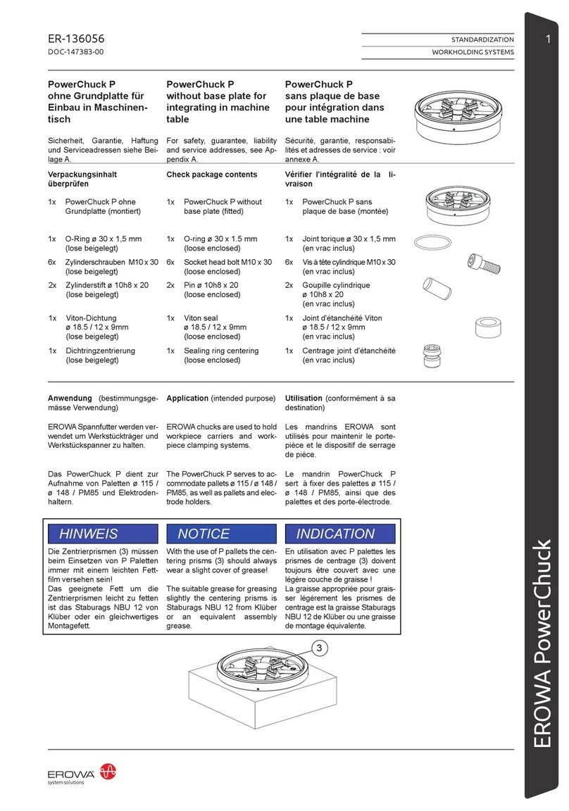
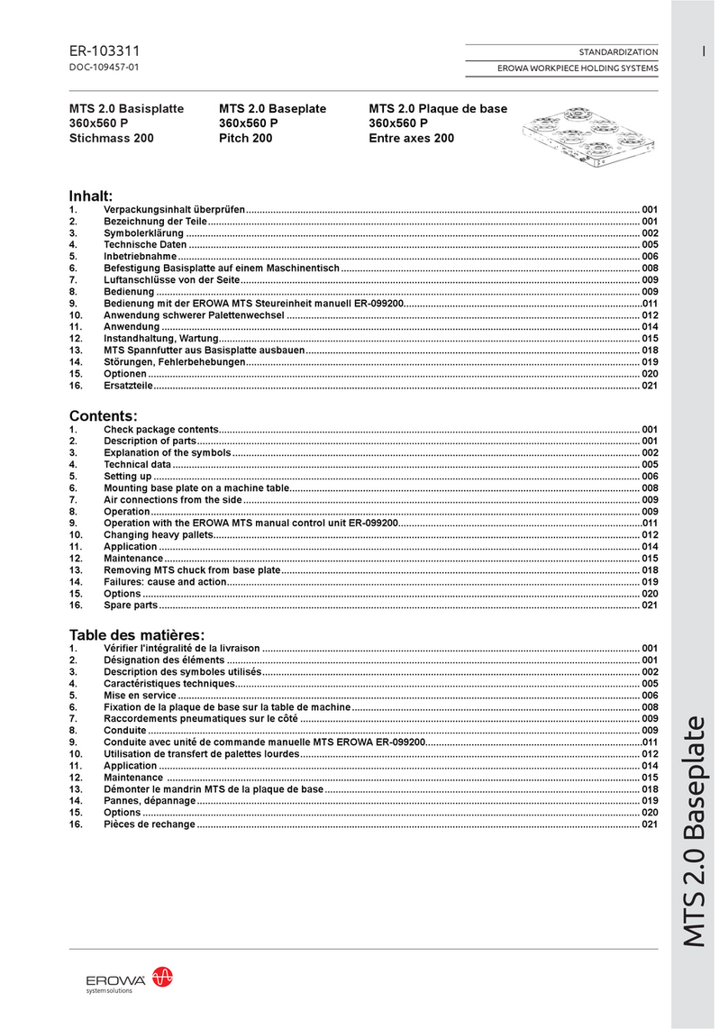
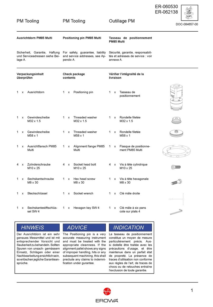
erowa PowerChuck P without base plate User manual

erowa

erowa PowerChuck P without base plate User manual

erowa MTS 2.0 User manual

erowa

erowa MTS 2.0 User manual

erowa PowerChuck P User manual

erowa

erowa PowerChuck P User manual

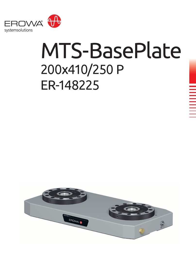
erowa MTS-BasePlate 200x410/250 P User manual

erowa

erowa MTS-BasePlate 200x410/250 P User manual

erowa ER-113300 User manual

erowa

erowa ER-113300 User manual

erowa ER-103311 User manual

erowa

erowa ER-103311 User manual

erowa ER-016880 User manual

erowa

erowa ER-016880 User manual

erowa MTS User manual

erowa

erowa MTS User manual

erowa MTS IntegralChuck S-P/A User manual

erowa

erowa MTS IntegralChuck S-P/A User manual

erowa ER-148426 User manual

erowa

erowa ER-148426 User manual
erowa PM85 Multi User manual

erowa

erowa PM85 Multi User manual

Popular Industrial Equipment manuals by other brands

Stahl SolConeX 8573/14 Series operating instructions

Stahl

Stahl SolConeX 8573/14 Series operating instructions

S&C PureWave AVC Instructions for installation and operation

S&C

S&C PureWave AVC Instructions for installation and operation

ZIEHL-ABEGG ZA top SM200.15D Assembly instructions

ZIEHL-ABEGG

ZIEHL-ABEGG ZA top SM200.15D Assembly instructions

Greenlee Ultra Tugger UT10-22 instruction manual

Greenlee

Greenlee Ultra Tugger UT10-22 instruction manual

BIG KAISER EWE Reader operating instructions

BIG KAISER

BIG KAISER EWE Reader operating instructions

Lintec HX-0020J Series instruction manual

Lintec

Lintec HX-0020J Series instruction manual

ABB HT847426 Operation manual

ABB

ABB HT847426 Operation manual

Power Tec 71539 instruction sheet

Power Tec

Power Tec 71539 instruction sheet

Cold Jet i3 MICROCLEAN 2 Operator's manual

Cold Jet

Cold Jet i3 MICROCLEAN 2 Operator's manual

Preiffer PKR 251 operating instructions

Preiffer

Preiffer PKR 251 operating instructions

Avantco Backhoe 170 Operator's manual

Avantco

Avantco Backhoe 170 Operator's manual

PLG PLUTO AR user manual

PLG

PLG PLUTO AR user manual

Festo YSRWJ A Series operating instructions

Festo

Festo YSRWJ A Series operating instructions

Battenfeld PLUS 250/50 manual

Battenfeld

Battenfeld PLUS 250/50 manual

comarme GEM F470 Use and maintenance manual

comarme

comarme GEM F470 Use and maintenance manual

A.B.S. Flexilo SPRING Assembly-, Operating-, and Filling Instructions

A.B.S.

A.B.S. Flexilo SPRING Assembly-, Operating-, and Filling Instructions

Endress+Hauser Prothermo NMT 539 Operating	 instruction

Endress+Hauser

Endress+Hauser Prothermo NMT 539 Operating instruction

SMC Networks EX600-ED Series Operation manual

SMC Networks

SMC Networks EX600-ED Series Operation manual

manuals.online logo
manuals.online logoBrands
  • About & Mission
  • Contact us
  • Privacy Policy
  • Terms and Conditions

Copyright 2025 Manuals.Online. All Rights Reserved.