Installation Procedures
Page 2
Operating The Pump
Page 3
Installation
The pump must be installed so that persons cannot accidentally
come into contact with the hot surface of the motor.
Pump Location
The pump is designed for tank mounting in vertical position. The
pump is positioned in a hole cut into the cover of the tank (upper
side) and is secured to the tank by four hexagon head screws
through the holes in the mounting flange. It is recommended to fit
a sealing gasket between the pump flange and tank.
NOTE: The pumps can only be mounted in vertical position.
The MTC 2 and 4 must have access to the tank from the drain
channel in the motor stool.
WARNING
MTC 2 AND 4
Figure 1
Pump mounting flange dimensions:
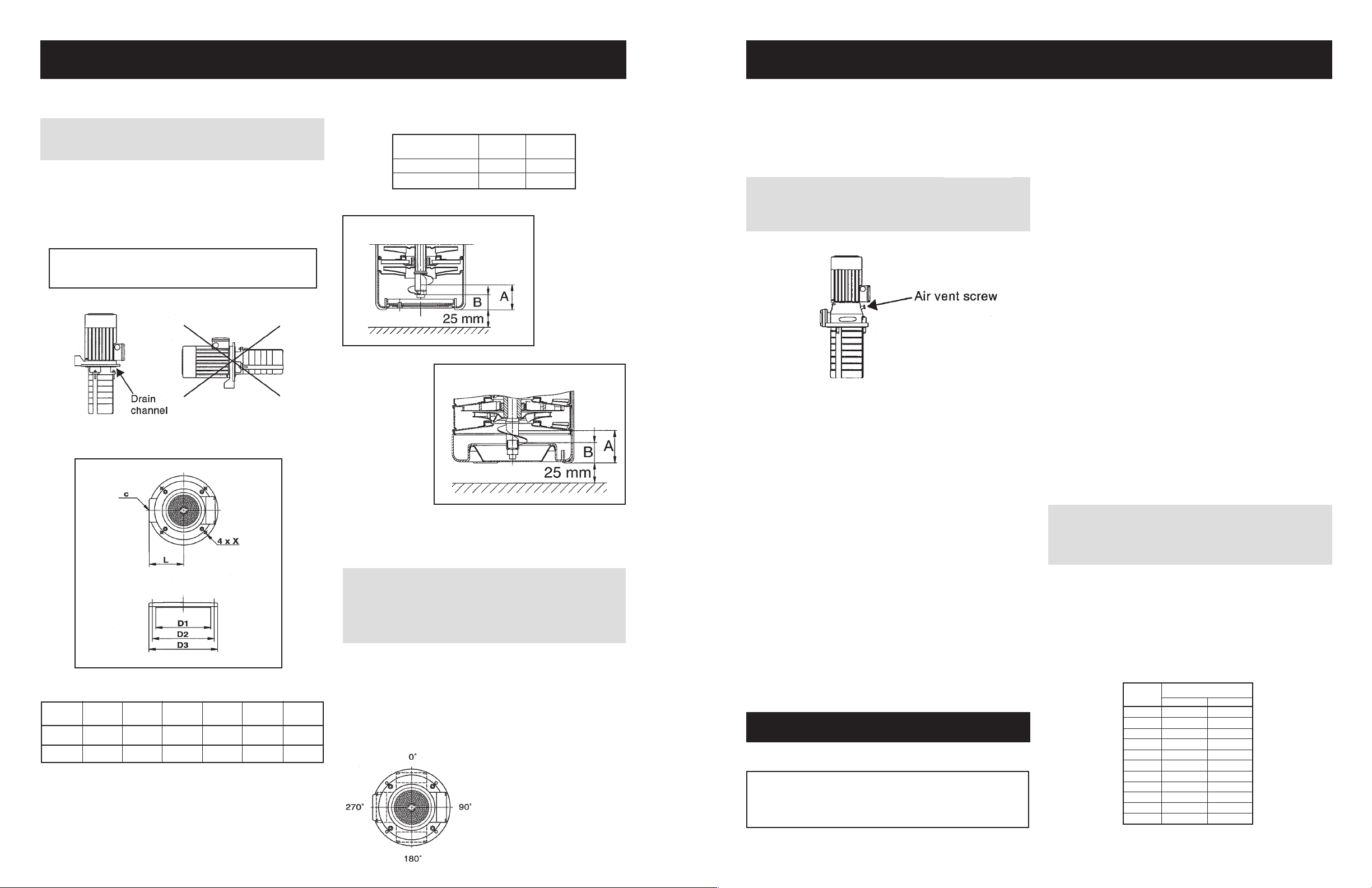
Suction Conditions
The bottom of the pump strainer must be at least 25 mm above the
bottom of the tank.
The pumps are designed to provide full performance down to a level
of A mm above the bottom of the strainer.
At a liquid level between A and B mm above the bottom of the
strainer, the built-in priming screw will protect the pump against dry
running.
Pump A B
Type
(mm/in) (mm/in)
MTC 2, 4 37/1.1 22/0.9
MTC 8, 12, 16 40/1.6 25/1.0
MTC 2 AND 4
MTC 8, 12 & 16
Electrical Connection
The electrical connection should be carried out in accordance with
local regulations.
The operating voltage and frequency are marked on the pump
nameplate. Please make sure that the motor is suitable for the
electricity supply on which it will be used.
The motor must be connected to a motor starter.
The terminal box, for motors up to and including 1.1 kW, can be
turned to four positions, in 90° steps, see Figure 4. Proceed as
follows:
1. Removed the four bolts
securing the motor to the
motor stool.
2. Turn the motor to the
required position.
3. Replace and tighten the
four bolts.
WARNING
Never make any connections in the pump terminal box unless
the electricity supply has been switched off.
If the pump is not connected to an electric installation, it must
be connected to an external mains switch.
Figure 2
Figure 3
The electric motor should be connected to the supply as shown in
the diagram inside the terminal box cover.
All other motors, from 1.5 kW and up, cannot be turned.
Start-up
WARNING – MTC 8, 12 and 16
Pay attention to the direction of the vent hole and take care to
ensure that the escaping water does not cause injury to persons
or damage to the motor or other components. See Figure 5.
Figure 5
Before starting the pump, make sure:
• that all pipe connections are tight.
• that the pump body is partly filled with liquid (partly submerged).
• that the strainer is not blocked by impurities.
Start the pump as follows:
1. Close the isolating valve on the discharge side of the pump.
2. See the correct direction of rotation of the pump on the motor
fan cover. When seen from the top, the pump should rotate
counter-clockwise.
3. Start the pump and check the direction of rotation.
4. MTC 2 and 4:
Open the discharge isolating valve a little.
MTC 8, 12 and 16:
Loosen the air vent screw in the motor stool.
5. MTC 2 and 4:
Completely open the discharge isolating valve.
MTC 8, 12 and 16:
When a steady stream of liquid runs out of the vent hole,
tighten the air vent screw and completely open the isolating
valve.
The pump has now been vented and is ready for operation.
Operation and Maintenance
Note: The pump is not allowed to run against a closed
discharge valve for more than approximately five minutes as
this will cause an increase in temperature/formation of steam in
the pump which may cause damage to the pump.
Lubrication and Maintenance
Pumps installed in accordance with these instructions require very
little maintenance.
When a mechanical shaft seal is fitted, it is self-adjusting and has
wear-resistant seal rings which are lubricated and cooled by the
pumped liquid.
The pump bearings are also lubricated by the pumped liquid. The
motor ball bearings are grease packed and sealed for life. No
further lubrication is necessary.
Pumps from 4 kW and up have angular contact bearings.
Filter
Chip trays, filters, etc. should be cleaned at regular intervals to
ensure a correct flow of liquid.
Periodic Checks
At regular intervals, depending on the conditions and time of
operation, the following checks should be made:
• Check the quantity of liquid and operating pressure.
• Check that there are no leaks.
• Check that the motor is not overheating.
• Check the tripping of the motor starter.
• Check that all controls are operating satisfactorily.
If the above checks do not reveal any abnormal operating details,
no further checks are necessary.
Should any faults be found, check the symptons with the Fault
Finding Chart, page 4.
Service
WARNING
If a pump has been used for pumping liquids which are injurious
tohumanhealthorpoisonous,itwillbeclassifiedascontaminated.
Do not turn the pump upside down during service. Residual
liquids from the chambers may damage the motor.
A contaminated pump must not be sent to Grundfos for service until
Grundfos has received all necessary details about the pumped
liquid, etc. Otherwise, Grundfos can refuse to accept the pump for
servicing.
Possible costs of returning the pump are to be paid by the customer.
Sound Pressure Level
D1 D2 D3 L X
MTC
(mm/in) (mm/in) (mm/in) (mm/in)
C
(mm/in)
2, 4 140/5.51 160/6.30 180/7.09 121/4.76 3⁄4" NPT 7/0.28
8, 12, 16 180/7.09 210/8.27 200/7.87 100/3.94 1 1⁄4" NPT 9/0.35
Figure 4
Operating The Pump
Motor
(kW) 50 HZ 60 HZ
0.25 <70 <70
0.37 <70 <70
0.55 <70 <70
0.75 <70 <70
1.1 <70 <70
1.5 <70 71
2.2 <70 71
3.0 <70 71
4.0 73 71
5.5 73 78
7.5 73 78
LpA [dB(A)]