manuals.online logo
Brands
  1. Home
  2. •
  3. Brands
  4. •
  5. ESAB
  6. •
  7. Welding System
  8. •
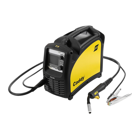
  9. ESAB Caddy 130 User manual

ESAB Caddy 130 User manual

This manual suits for next models

5

Other ESAB Welding System manuals

ESAB LHF 400 User manual

ESAB

ESAB LHF 400 User manual

ESAB Super Bantam 225 AC User manual

ESAB

ESAB Super Bantam 225 AC User manual

ESAB Fabricator 252i User manual

ESAB

ESAB Fabricator 252i User manual

ESAB AK 400 User manual

ESAB

ESAB AK 400 User manual

ESAB Origo Arc 458T Guide

ESAB

ESAB Origo Arc 458T Guide

ESAB Buddy Mig 500i User manual

ESAB

ESAB Buddy Mig 500i User manual

ESAB Caddy Mig C200i User manual

ESAB

ESAB Caddy Mig C200i User manual

ESAB A22 POB Instructions for use

ESAB

ESAB A22 POB Instructions for use

ESAB ORIGO Mig C280 PRO User manual

ESAB

ESAB ORIGO Mig C280 PRO User manual

ESAB Aristo YardFeed 2000 User manual

ESAB

ESAB Aristo YardFeed 2000 User manual

ESAB Origo Tig 3000i User manual

ESAB

ESAB Origo Tig 3000i User manual

ESAB Origo Feed 304N P4 User manual

ESAB

ESAB Origo Feed 304N P4 User manual

ESAB CIGWELD Transmig 255i User manual

ESAB

ESAB CIGWELD Transmig 255i User manual

ESAB Origo Mig 4002c User manual

ESAB

ESAB Origo Mig 4002c User manual

ESAB EMP 255ic User manual

ESAB

ESAB EMP 255ic User manual

ESAB Aristo Mig U4000iw User manual

ESAB

ESAB Aristo Mig U4000iw User manual

ESAB ES 300i User manual

ESAB

ESAB ES 300i User manual

ESAB EM235ic User manual

ESAB

ESAB EM235ic User manual

ESAB PCM-500i User manual

ESAB

ESAB PCM-500i User manual

ESAB Aristo Mig WeldCloud U5000i User manual

ESAB

ESAB Aristo Mig WeldCloud U5000i User manual

ESAB MIG C250i User manual

ESAB

ESAB MIG C250i User manual

ESAB Origo Mig 3001i User manual

ESAB

ESAB Origo Mig 3001i User manual

ESAB MobileFeed 201 AVS User manual

ESAB

ESAB MobileFeed 201 AVS User manual

ESAB Multimaster 300 User manual

ESAB

ESAB Multimaster 300 User manual

Popular Welding System manuals by other brands

Razorweld RAZORCUT45 instruction manual

Razorweld

Razorweld RAZORCUT45 instruction manual

Lincoln Electric Fleet 500 Operator's manual

Lincoln Electric

Lincoln Electric Fleet 500 Operator's manual

Migatronic OMEGA 220 quick guide

Migatronic

Migatronic OMEGA 220 quick guide

Magmaweld ID 300T DC user manual

Magmaweld

Magmaweld ID 300T DC user manual

Sealey POWERMIG Series instructions

Sealey

Sealey POWERMIG Series instructions

Defort 98291254 user manual

Defort

Defort 98291254 user manual

Hobart Welding Products AirForce 375 owner's manual

Hobart Welding Products

Hobart Welding Products AirForce 375 owner's manual

GF MSA 330 instruction manual

GF

GF MSA 330 instruction manual

Hakko Electronics FX-888D instruction manual

Hakko Electronics

Hakko Electronics FX-888D instruction manual

Abicor Binzel ABIPLAS WELD 100 W operating instructions

Abicor Binzel

Abicor Binzel ABIPLAS WELD 100 W operating instructions

EWM Taurus 355 Basic TDM operating instructions

EWM

EWM Taurus 355 Basic TDM operating instructions

Thermal Dynamics PakMaster 100 XL plus operating manual

Thermal Dynamics

Thermal Dynamics PakMaster 100 XL plus operating manual

Berner PLASMACUT 54 instruction manual

Berner

Berner PLASMACUT 54 instruction manual

Pro Spot PR-155 Assembly instructions

Pro Spot

Pro Spot PR-155 Assembly instructions

Forney 210 operating manual

Forney

Forney 210 operating manual

Thermal Arc 400S operating manual

Thermal Arc

Thermal Arc 400S operating manual

Lincoln Electric HANDYMIG 170I Operator's manual

Lincoln Electric

Lincoln Electric HANDYMIG 170I Operator's manual

GYS PROTIG 201 AC/DC Original instructions

GYS

GYS PROTIG 201 AC/DC Original instructions

manuals.online logo
manuals.online logoBrands
  • About & Mission
  • Contact us
  • Privacy Policy
  • Terms and Conditions

Copyright 2025 Manuals.Online. All Rights Reserved.

0740 800 043 Valid for serial no. 301--xxx--xxxx to 220--xxx--xxxx040906
LHN 130/140/200
Caddy 130/140/200
cmha2p00
Service manual
-- 2 --
cmha2de0
LIST OF CONTENTS Page
READ THIS FIRST 2........................................................
COMPONENT DESCRIPTION, LHN 130/140/200 4.............................
WIRING DIAGRAM LHN 130 7...............................................
WIRING DIAGRAM LHN 140 valid before ser.no. 011--xxx--xxxx 8........................
WIRING DIAGRAM LHN 140 valid for ser.no. 011--xxx--xxxx and 220--xxx--xxxx 9...............
WIRING DIAGRAM LHN 200 valid before ser.no. 011--xxx--xxxx 10........................
WIRING DIAGRAM LHN 200 valid for ser.no. 011--xxx--xxxx and 220--xxx--xxxx 11...............
COMPONENT POSITIONS, CIRCUIT BOARD AP01 12..........................
DESCRIPTION OF OPERATION, CIRCUIT BOARD AP01 14.....................
CHECKING THE GATE PULSES 19...........................................
CIRCUIT DIAGRAM, CIRCUIT BOARD AP02 20.................................
CIRCUIT DIAGRAM, CIRCUIT BOARD AP03 22.................................
MOS TESTER 24............................................................
SOFT STARTING 25.........................................................
ASSEMBLY/DISASSEMBLY 26................................................
LOAD CHARACTERISTICS 30................................................
TECHNICAL DATA 31........................................................
INSTALLATION 32...........................................................
OPERATION 33.............................................................
MAINTENANCE 34..........................................................
SPARE PARTS 35...........................................................
NOTES 35..................................................................
READ THIS FIRST
Maintenance and repair work should be performed by an experienced person, and electrical
work only by a trained electrician. Use only recommended replacement parts.
This service manual is intended for use by technicians with electrical/electronic training for
help in connection with fault--tracing and repair.
Use the wiring diagram as a form of index for the description of operation. The circuit
board is divided into numbered blocks, which are described individually in more detail in
the description of operation. All component names in the wiring diagram are listed in the
component description.
This manual contains details of all design changes that have been made up to and including
August 2004.
The manual is valid for the LHN 130, LHN 140 and LHN 200 with serial numbers:
301--xxx--xxxx, 508--xxx--xxxx, 535--xxx--xxxx, 540--xxx--xxxx, 628--xxx--xxxx,
011--xxx--xxxx and 220--xxx--xxxx.
The LHN 130, LHN 140 and LHN 200 are designed and tested in accordance with
international and European standard IEC/EN 60974--1 and EN 50199.
On completion of service or repair work, it is the responsibility of the person(s) etc.
performing the work to ensure that the product does not depart from the requirements
of the above standard.
Rights reserved to alter specifications without notice.
-- 3 --cmha2de1
WARNING
READ AND UNDERSTAND THE INSTRUCTION MANUAL BEFORE INSTALLING OR OPERATING.
ARC WELDING AND CUTTING CAN BE INJURIOUS TO YOURSELF AND OTHERS. TAKE PRECAU-
TIONS WHEN WELDING. ASK FOR YOUR EMPLOYER’S SAFETY PRACTICES WHICH SHOULD BE
BASED ON MANUFACTURERS’ HAZARD DATA.
ELECTRIC SHOCK -- Can kill
SInstall and earth the welding unit in accordance with applicable standards.
SDo not touch live electrical parts or electrodes with bare skin, wet gloves or wet clothing.
SInsulate yourself from earth and the workpiece.
SEnsure your working stance is safe.
FUMES AND GASES -- Can be dangerous to health
SKeep your head out of the fumes.
SUse ventilation, extraction at the arc, or both, to keep fumes and gases from your breathing zone and
the general area.
ARC RAYS -- Can injure eyes and burn skin.
SProtect your eyes and body. Use the correct welding screen and filter lens and wear protective
clothing.
SProtect bystanders with suitable screens or curtains.
FIRE HAZARD
SSparks (spatter) can cause fire. Make sure therefore that there are no inflammable materials nearby.
NOISE -- Excessive noise can damage hearing
SProtect your ears. Use ear defenders or other hearing protection.
SWarn bystanders of the risk.
MALFUNCTION -- Call for expert assistance in the event of malfunction.
PROTECT YOURSELF AND OTHERS!
WARNING !
STATIC ELECTRICITY can damage circuit
boards and electronic components.
SObserve precautions for handling electrostatic
sensitive devices.
SUse proper static--proof bags and boxes.
ESD
-- 4 --
cmha2de1
COMPONENT DESCRIPTION, LHN 130/140/200
This component description relates to the wiring diagrams on pages 7 -- 11.
The LHN 130/140/200 rectifier power units are primary switched type, using parallel--
connected MOSFET transistors as switching devices. Switching frequency is 36 kHz.
The conduction interval ranges between zero and 11 µs, depending on the welding current
being supplied. The conduction time and frequency are controlled by circuit board AP01.
AP01 Main circuit board with control electronics. See the description on page 14.
AP02 Circuit board with power transistors for the positive pole:see description on
page 20.
WARNING: these transistors are at mains voltage.
AP03 Circuit board with power transistors for the negative pole:see description
on page 22.
WARNING: these transistors are at mains voltage.
AP04 Suppression circuit board and protection against transient voltages:
protects the secondary diodes against transient voltages.
Replaced by capacitors C06 from serial number 628--xxx--xxxx.
See “transient protection, rectifer unit V03, V04” on page 6.
AP05 Suppression circuit board, EMC. Protects from mains borne interference
to/from the machine. Mounted from serial no. 540--xxx--xxxx.
LHN 200: The ferrite ring cores L06 and L07 are included in AP05.
cmha2
e21
Circuit diagram and component positions circuit board AP05
C01 Capacitor, 0.1 µF, 1000 VDC, transient protection.
C02 Capacitor, 1000 µF, buffer/smoothing capacitor. This capacitor takes about
two minutes to discharge after disconnecting the equipment from mains.
C03 See C02. Not mounted in LHN 130/140.
-- 5 --cmha2de1
C04 Capacitor, 0.1 µF, 1000 VDC, protects the equipment against RFI.
C05 2 -- capacitors, 4.7 µF: see L02. Not mounted in LHN 130.
C06 2 -- capacitors, 12 nF. Protection against transient voltages.
Replacing AP04 from serial number 628--xxx--xxxx.
See “transient protection, rectifer unit V03, V04” on page 6.
C06 is replaced by ferrite rings (L03--L05) from ser. no. 011--xxx--xxxx.
EV01 Fan, 24 VDC.
Note: The fans are different in LHN 130 and LHN 140/200.
In LHN 130 must not the same fan be used as in LHN 140/200.
HL01 Indicating lamp, 28 V, white, showing that the mains power supply is
turned on.
L01 Secondary inductor.
L02 Inductor. Not mounted in LHN 130.
Together with C05 and V06, this forms an LC circuit which reduces the
risk of the arc extinguishing at low welding currents.
Capacitor C05 in the LC circuit charges when V03 conducts. The circuit
can temporarily maintain a high output voltage at low welding current,
reducing the risk of the arc being extinguished.
Diode V06 protects capacitor C05 against negative voltage.
L03 LHN 140: Primary inductor, for improving the machine’s form factor, i.e.
reducing mains loading.
LHN 200: Ferrite ring core (from serial number 011--xxx--xxxx).
L04 LHN 200: Coil, included in conductor 013.
LHN 140: Ferrite ring core (from serial number 011--xxx--xxxx).
L05 Ferrite ring core (from serial number 011--xxx--xxxx).
L06, L07 LHN 200: Ferrite ring cores, included in AP05.
QF1 Mains switch: 2--pole in the LHN 130/140 and 3--pole in the LHN 200.
RP01 Potentiometer for adjusting welding current, 10 kΩ,2W.
RS01 Shunt, 120 mV at 130 A or 140 A or 200 A respectively.
RV01 Varistor, 275 V, transient voltage protection. Only LHN 130/140.
From serial no. 540--xxx--xxxx the transient voltage protection is included
at circuit board AP05.
RV01--RV03 Varistors, 480 V, transient voltage protection. Only LHN 200.
From serial no. 540--xx--xxxx the transient voltage protection is included at
circuit board AP05.
ST01 Thermal overload cutout, fitted in the main transformer (TC02) winding.
LHN 130/140: interrupts at 130 ˚C, recloses at 100 ˚C.
LHN 200: interrupts at 150 ˚C, recloses at 130 ˚C.
TC01 Control power supply transformer. Primary side is supplied at 230 V or
400 V respectively. Dual secondary windings supply 20.5 V and 17 V to
circuit board AP01.
TC02 Main transformer: see on page 29 for installation instructions.
-- 6 --
cmha2de1
V01, V02 Mains rectifier diode bridge, 35 A, 1200 V. After replacing the rectifier
bridges, the machine must be soft--started: see instructions on page 25.
Rectifier bridge V02 is only mounted in LHN 200.
V03, V04 Rectifier and freewheel diodes.
V03 rectifies the welding current.
During the time interval between two voltage pulses from transformer
TC02, the freewheel diodes V04 maintain the welding current from
inductor L01.
Before serial number 628--xxx--xxxx:
V03 consists of six parallel--connected diodes, and V04 consists of eight
parallel--connected diodes. V03 and V04 are mounted on the same cooling
fins. If any of the diodes is/are faulty, the entire cooling fin unit must be
replaced, as the diodes are soldered to it. For spare parts see the spare parts
list item 430 (LHN 140/200) and item 830 (LHN 130)
From serial number 628--xxx--xxxx:
A new rectifier unit is introduced. On the cooling fins in LHN 130/140 is
one diode module mounted and in LHN 200 are two diode modules
mounted. Each diode module has two diodes.
See page 27 for fitting instructions.
V05 LED, yellow.
Lit when thermal overload cutout ST01 opens due to high temperature.
V06 Diode: see L02. Not mounted in LHN 130.
X01 Mains terminal block: 4--pole or 8--pole respectively. Replaced by circuit
board AP05 from serial no. 540--xxx--xxxx.
XS01--XS13 Sleeve connectors.
XS11 LHN 140/200: 12--pole connector for connection of remote control unit.
XS12 Welding terminals (2 -- OKC connectors).
TRANSIENT PROTECTION, RECTIFIER UNIT V03, V04
C06
LHN 130/140 LHN 200
before serial number 628--xxx--xxxx
LHN 130/140/200
with serial number 628--xxx--xxxx
and 220--xxx--xxxx
WIRING DIAGRAM LHN 130
cmha2e20
-- 7 --cmha2de1
cmha2e01
WIRING DIAGRAM LHN 140 valid before ser.no. 011--xxx--xxxx
-- 8 --
cmha2de1
WIRING DIAGRAM LHN 140 valid for ser.no. 011--xxx--xxxx and 220--xxx--xxxx
-- 9 --cmha2de1
WIRING DIAGRAM LHN 200 valid before ser.no. 011--xxx--xxxx
cmha2e02
-- 1 0 --
cmha2de1