ESBE DN20 User manual

87/6/0,6
0
5
15
Psi/bar/Mpa
+131 +55
+32 +0
+212 +100
SERIES FUNCTION
ESBE
GDA311
ESBE
GRA311
ARA600
ESBE
GFA311
ESBE System Units
CIRCULATION UNIT DN20
Mtrl.nr. 98141118 • Ritn.nr. 7948 vers. A• Rev. 2023‒03‒29
Dimensions ▯ Cabling Mounting position
Series GDA311
Series GRA311
Series GFA311
2Remove insulation
ESBE AB
Bruksgatan 22
SE‒333 75 Reftele
www.esbe.eu
174
90
214 87
188
3
6
0
º
0º
Remove actuator
Series GRA311
Remove
Pull
LVD 2014/35/EU
EMC 2014/30/EU
RoHS 2011/65/EU
ErP 2009/125/EU
PED 2014/68/EU, article 4.3
EnEV 2014
SI 2016 No. 1101
SI 2016 No. 1091
SI 2012 No. 3032
SI 2010 No. 2617
SI 2016 No. 1105
Pull up
insulation 7mm

6
3
Press
1
SERIES ARA600 Prop
Pro
P
SERIES ARA600 3-Point
S
ERIE
S
AR
A60
SERIES ARA600 2-Point
https://esbe.eu/group/
products/rotary-actuators
Commissioning actuator Commissioning
fixed temperature
Series GFA311
CCWNCW
bkbu bn
Electric installation
www.esbe.eu
Fit supply pipes
Adjust wallbracket
Assembling on wall 4
Assemble insulation
30mm
OUICK FIT!
3
Assemble actuator
Series GRA311
Press
Press
5
»C
l
Click!
Assemble lower insulation
L(bn)
N(bu)
PE (gn)
PWM (bn)
GND (bu)
Power Signal
25°C22°C 33°C 40°C 47°C 54°C 60°C
SERIES VTA
S
ERIE
S
V
SERIES VTA
https://www.esbe.eu/global/en/pro-
ducts/thermostatic-mixing-valves
40-50Nm c/c 90mm
0
20 MINUTES
Commissioning
Flow
Filling and
venting
Open
White mark, indicate
check valve position
45
o
Filling and venting
Preparation
Open Closed
90
o
Checkvalve position
Flow
OPEN
AIR
CLOSE
Assemble removed knob

0,2 0,4 0,6 0,8
0,7 1,4 2,2 2,9
20
15
10
7
5
10
0
20
30
40
50
60
50
40
30
20
10
70
10
0
20
30
40
50
60
50
40
30
20
10
0,2 0,4 0,6 0,8
0,7 1,4 2,2 2,9
20
15
10
7
5
70
0,2 0,4 0,6 0,8
0,7 1,4 2,2 2,9
20
15
10
7
5
10
0
20
30
40
50
60
50
40
30
20
10
70
0,2 0,4 0,6 0,8
0,7 1,4 2,2 2,9
20
15
10
7
5
10
0
20
30
40
50
60
50
40
30
20
10
70
0,2 0,4 0,6 0,8
0,7 1,4 2,2 2,9
20
15
10
7
5
10
0
20
30
40
50
60
50
40
30
20
10
70
Circulation Unit Performance Circulation Unit Performance
Variable differential
pressure - p-v
Constant differential
pressure - p-c
Constant speed
PUMP CURVE
I, II, III
CONTROL MODE
NORMAL
OPERATION FAULT
Ext.
iPWM 1 iPWM 2
NORMAL
OPERATION
FAULT
Display
CONTROL MODE
Variable differential
pressure - p-v
Constant differential
pressure - p-c
External signal (PWM)
PUMP CURVE
Heating output GDA311 DIRECT SUPPLY Heating output GRA311 MIXING FUNCTION
Constant differential pressure Variable differential pressure Ext iPWM 1/ iPWM 2
I, II, III
V
DE
geprüfte
Sicherheit
Para STG
15/8-60/O
ESBE
0000000
19W51
1900000
EX
EXT.
iPWM1
iPWM1
iPWM2
iPWM2
[m3/h ]
[m3/h ]
[m3/h ]
[m3/h ]
[l/s]
[l/s]
[l/s]
[l/s]
Flow FlowFlow Flow
[m3/h ]
[m3/h ]
[l/s]
[l/s]
Flow Flow
0,2 0,4 0,6 0,8
0,7 1,4 2,2 2,9
20
15
10
7
5
10
0
20
30
40
50
60
50
40
30
20
10
70
Constant differential pressure Variable differential pressure Ext iPWM 1/ iPWM 2
∆P
[kPa]
∆P
[kPa]
∆P
[kPa]
[kW] [kW] [kW]
∆P
[kPa]
∆P
[kPa]
∆P
[kPa]
[kW] [kW] [kW]
I I I I I I
I I I I I I
I I I II I I I
I I
I I
Recommended
pump settings
Applications
I, II, III I, II, III
iPWM 1/
iPWM 2
Ext.
= Factory settings
Factory setting
Factory
setting
+
Pump Settings
Hold
8 sec 1 sec
1 sec
30 sec
10 min
Hold
LED display Status
Locked
Unlocked
Venting
Factory
setting
Hold
8 sec
Hold
8 sec
Hold
8 sec
1. Hold 2. 3. 4.
Manual
restart
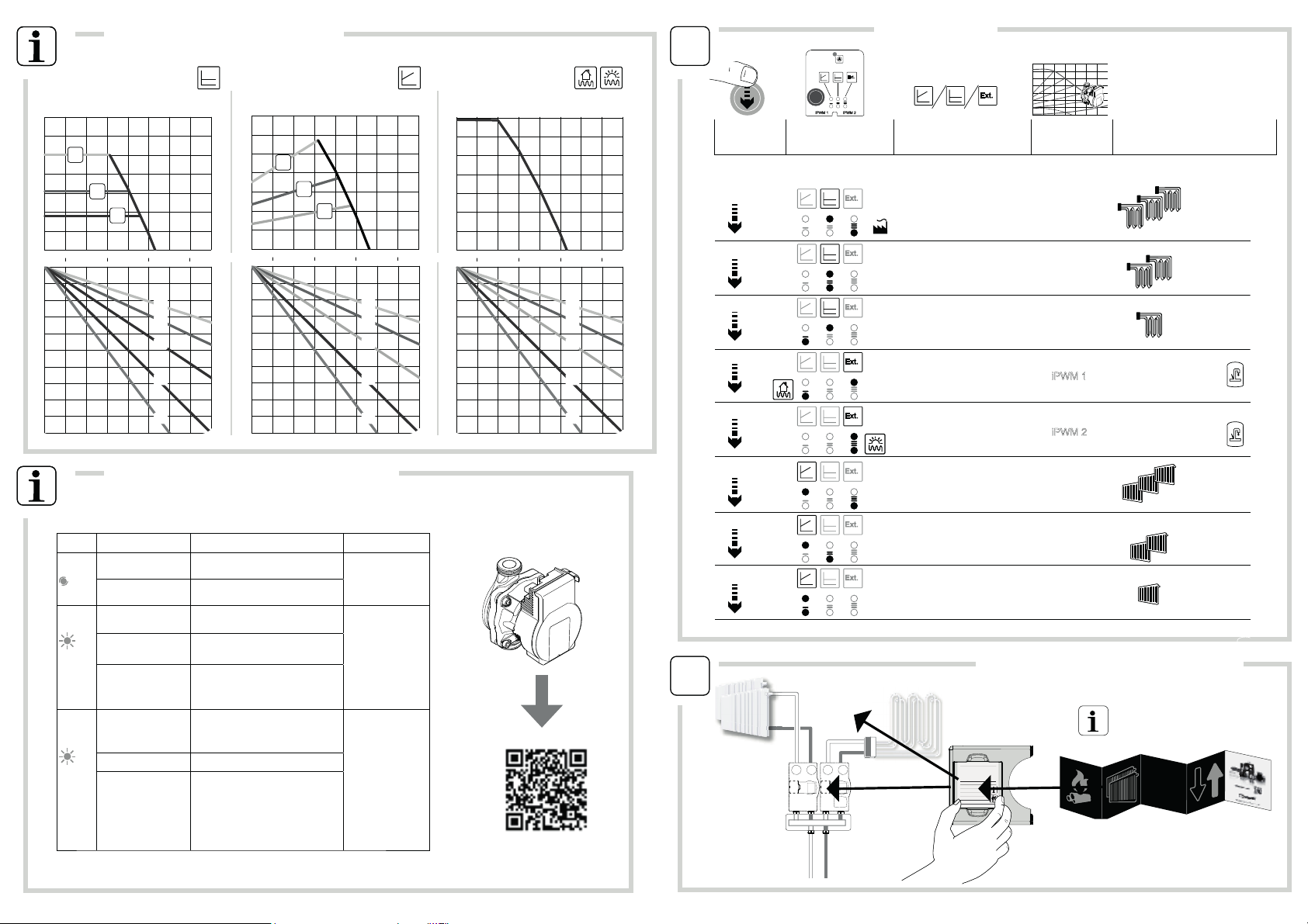
click Pump curve
Constant speed
iPWM 1
Constant differential II
Constant speed
iPWM 2
Ext.
Ext.
Ext.
4
2
5
Ext.
iPWM 1 iPWM 2
Ext.
Constant differential III
1
Ext.
Constant differential I
Ext.
3
Variable differential III
Variable differential II
Variable differential I
Ext.
Ext.
Ext.
6
7
8
http://www.esbe.eu/global/en/
products/circulation units
WILO - Faults, Causes and Remedies
Application
information
Expose application info using leaflet
0,2 0,4 0,6 0,8
0,7 1,4 2,2 2,9
20
15
10
7
5
10
0
20
30
40
50
60
50
40
30
20
10
70
0,2 0,4 0,6 0,8
0,7 1,4 2,2 2,9
20
15
10
7
5
10
0
20
30
40
50
60
50
40
30
20
10
70
0,2 0,4 0,6 0,8
0,7 1,4 2,2 2,9
20
15
10
7
5
10
0
20
30
40
50
60
50
40
30
20
10
70
Circulation Unit Performance
Heating output GFA311 FIXED TEMPERATURE
[m3/h ]
[m3/h ]
[l/s]
[l/s]
Flow Flow Flow
[m3/h ]
[l/s]
Constant differential pressure Variable differential pressure Ext iPWM 1/ iPWM 2
6
7
∆P
[kPa]
∆P
[kPa]
∆P
[kPa]
[kW] [kW] [kW]
I I I I I I
I I I I
II
LED Faults Cause Remedy
Lights up
red Blocking Rotor blocked Activate manual
restart or contact
customer service
Contacting/ winding Winding defective
Flashes
red Under/overvoltage Power supply too low/high on mains
side
Check mains voltage
and operating con-
ditions, and request
customer service
Excessive
module temperature Module interiour too warm
Short-circuit Motor current too high
Flashes
red/
green
Generator operation
Water is flowing through the pump
hydraulics, but there is no mains vol-
tage at the pump
Check the mains
voltage, water
quantity/pressure
and the ambient
conditions
Dry run Air in the pump
Overload
Sluggish motor, pump is operated
outside of its specifications (e.g. high
module temperature). The speed is
lower than during normal operation
Recommended Alternative
Pump Settings
Click LED display Control mode Pump
setting Application
vz
Other ESBE DC Drive manuals


