Esco systeQ-S 7665 User manual

D
GB
I
F
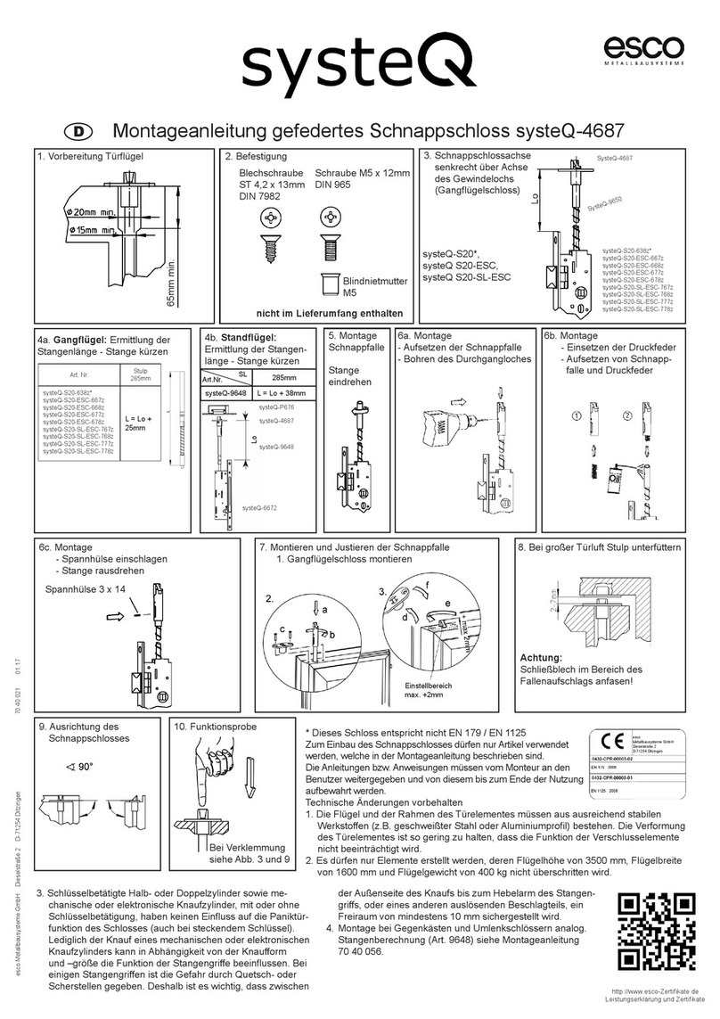
Montageanleitung
Fluchttürgegenkasten systeQ-S 7665
mit Motormodul systeQ-S 765M
Funktionseinheit
Motormodul
systeQ-S 765M
Fluchttürgegenkasten
systeQ-S 7665
Rohrrahmenschloss mit Fluchttürfunktion
systeQ-S-ESC
systeQ-S-SL-ESC

23
Inhaltsverzeichnis
1. Allgemeine Hinweise
1.1 Produktbeschreibung……………………………………................................……… 3
1.2 Bestimmungsgemäße Verwendung……………………...................................…… 3
1.3 Funktionsweise………………………………………….................................………....3
1.4 Anschlussplan.....................................................................................................4-5
1.5 Technische Daten..................................................................................................5
2. Montage der Funktionseinheit
2.1 Stangenzuschnitt...............................……...........…………................................…6
2.2 Einbau- und Befestigungsanweisung.................................................................…7
3. Einstellmöglichkeiten..........................................................................................8
4. Funktionsbeschreibung......................................................................................9

23
1. Allgemeine Hinweise
1.1 Produktbeschreibung
Fluchttürgegenkasten für Rohrrahmenschlösser mit Fluchttürfunktion in Rohrrahmentüren. Prüfungen nach
EN 179, EN 1125 und EN 12209.
1.2 Bestimmungsgemäße Verwendung
Die genannten Fluchttürgegenkästen sind ausschließlich für ihre bestimmungsgemäße Verwendung
zugelassen:
Maximalmaße von Gang- und Standügel: 3500mm x 1600mm h x b, max. 400kg pro Flügel.
Zugelassener Temperaturbereich: -25°C bis +70°C
Max. Leistungsaufnahme: 100W
Versorgungsspannung: 24V DC ±10%
1.3 Funktionsweise
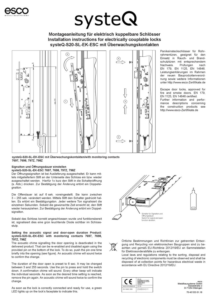
Der Motorantrieb SysteQ-S 765M wird oberhalb des Fluchttürgegenkastens systeQ-S 7665 eingehangen
und verbunden. Über Steuereingänge entriegelt der Motor die Tür einügelig oder zweiügelig. Nach
einer einstellbaren Zeit wird die Tür wieder verriegelt. Eine Ansteuerung über Türönungstaster, Bewe-
gungsmelder oder
anderen Systemen ist ebenso möglich, wie die Kombination mit Drehtürantrieben.
Werden die Steuereingänge dauerbetätigt, verbleibt der Motor in entriegelter Position (nur bei eingeschalteter
Dauerentriegeltfunktion). Das bedeutet, der Fallen- und Riegelauswerfer im Gegenkasten bleibt heraus-
gedrückt, das Schloss im Gangügel verriegelt nicht. Zusätzlich bleiben die Verriegelungsstangen oben
und unten am Anti-Panik-Gegenkasten eingezogen (zweiügelig).
Bei ausgeschalteter Dauerentriegeltfunktion ist eine Dauerbetätigung der Eingänge nicht möglich. Die
Zustände der Tür werden über integrierte Sensoren elektrisch erfasst. Bei Stromausfall werden der
Fallen- und Riegelauswerfer sowie die Verriegelungsstangen am Anti-Panik-Gegenkasten entkoppelt.
Die mechanische Entriegelung über die Drehbewegung der Nuss (Gri- und Druckstangen, Türdrücker)
ist zu jeder Zeit möglich. Die mechanische Panikfunktion ist vorrangig geschaltet und immer gewährleistet.
Über einen Taster können folgende Veränderungen durchgeführt werden:
- Der Signalton kann ein und ausgestellt werden
- Die Entriegelungszeit ist einstellbar
- Die Dauerentriegeltfunktion kann bestimmt werden
In Kombination mit Drehtürantrieben sind verschiedene Anschlussmöglichkeiten gegeben:
- Der motorische Gegenkasten empfängt die Önungssignale und gibt diese weiter an
die Drehtürantriebe.
- Die Önungssignale kommen an die Drehtürantriebe. Der motorische Gegenkasten
wird an die Drehtürantriebe als „Slave“ angeschlossen und empfängt die Önungssignale.
- Beide Komponenten werden parallel angesteuert und fungieren unabhängig voneinander.
Eine vorgeschaltete Schaltung übernimmt ggf. die Steuerung.

45
Pos Farbe Bedeutung Anmerkung
1 braun/grün +24V Versorgung
2 weiß/grün +24V //
3 rot/blau GND, 0V //
4 rosa/grau GND, 0V //
5 violett Störungsmeldung OC Ausgang
6 schwarz Tür 1-ügelig oen OC Ausgang
7 rot A RS485
8 blau Einügelig önen Optokoppler Eingang
9 rosa B RS485
10 grau Zweiügelig önen Optokoppler Eingang
11 gelb Tür 2-ügelig önen OC Ausgang
12 grün GND, OV Riegelüberwachung Gegenkasten (optional)
13 braun Vcc (optional) Fallenüberwachung, Gegenkasten (optional)
14 weiß GND, OV Bezug Gegenkasten
1.4 Anschlussplan

45
Eingänge: - Önen, einügelig (Optokopplereingang gegen GND schalten)
- Önen, zweiügelig (Optokopplereingang gegen GND schalten)
Ausgänge: - Einügelig oen (Open Collector, max. 30V, 0,1A schaltet gegen GND)
- Zweiügelig oen (Open Collector, max. 30V, 0,1A schaltet gegen GND)
- Störung (Open Collector, max. 30V, 0,1A schaltet gegen GND)
Der Netzanschluss darf nur von einer elektrotechnischen Fachkraft vorgenommen werden.
Beim Anschluss an 230V besteht Lebensgefahr.
Das Netzteil muss eine Stromquelle mit begrenzter Leistung gemäß EN60950 sein.
Der Ausgangsstrom darf nicht mehr als 5 Ampere betragen.
Die elektrischen und elektronischen Komponenten entsprechen den CE Normen.
CE- Konformität gemäß 2014/30/EU
- EN 61000-6-1 EMV Grundnorm Störfestigkeit
- EN 61000-6-3 EMV Grundnorm Störaussendung
- EN 60950 Gerätesicherheit
1.5 Technische Daten
Nennspannung: 24V
Stromaufnahme: 4 A max.
Standby: 50mA
Eingänge: optisch entkoppelt
Ausgänge: Open Collector max. 30V, 0,1A
Kabeldurchmesser: 6,5mm
Kabeltyp: LIYY 14x0,14mm²
Kabellänge: 10m
Kupplungsfunktion: Arbeitsstrom, stromlos entkuppelt
Entriegelungszeit: 4s Voreinstellung, einstellbar
Signaltonfunktion: schaltbar
Schnittstelle: RS 485 optional
Es ist ein Netzteil erforderlich, 24V/DC 100W geregelt.
Die maximale Kabellänge (Systemkabel) vom Schloss bis zur Anschlussdose darf 10m nicht überschreiten.
Anderenfalls sind die Kabeldurchmesser anzupassen, um einen Spannungsabfall zu vermeiden.

67
Abbildung 1
Zu Abbildung 1:
2. Montage der Funktionseinheit
2.1 Stangenzuschnitt
Dornmaß Dornmaßbrücke Erläuterung
35-45 mm – Direkte Verschraubung mit der Schlossstulp
50-60 mm 1 Verbauung zwischen Stulp und Motoreinheit
65-75 mm 2 Verbauung zwischen Stulp und Motoreinheit
80-85 mm 3 Verbauung zwischen Stulp und Motoreinheit
Der jeweilige Gegenkasten ist passend zum Dornmaß gefertigt.
Die Adapterplatte wird mit dem Motormodul werkseitig montiert.
35-45 Dorn
50-60 Dorn
65-75 Dorn
80-90 Dorn
1
2
Standügel:
L = Lo + 42mm
9648
SL
Art.Nr.
255,5mm
9647 L = Lu + 57mm
SL
Art.Nr.
SL = Stangenlänge
Standügel:
285mm
9650 L = Lu + 25mm
SL
Art.Nr.
Gangügel:
L = Lo + 42mm
9648
SL
Art.Nr.
255,5mm
9647 L = Lu + 57mm
SL
Art.Nr.
4685
9648
systeQ-S
765M
Lu
Lo
systeQ-S
7665
9647
9653
9651
6658
6668
6678
7668
7678
7688
Lu
Lo
9647
9653
9651
4685
9648
4686
9650
658Z
668Z
678Z
768Z
778Z
788Z
L1
1 2
systeQ-S-
ESC
systeQ-S-
SL-ESC
systeQ-S-
ESC
systeQ-S-
SL-ESC
systeQ-S
7665
systeQ-S
765M

67
2.2 Einbau- und Befestigungsanweisung
Kabelführung
Abbildung 3
ggf. Kabelbinder
Zu Abbildung 3:
Die Kabelführung führt den Kabelstrang von
den Kopplungsstangen weg. Sie ist beidseitig
nutzbar. Hierzu wird der 14-polige Stecker
in die vordere Aufnahme der Kabelführung
geklipst. Im Anschluss wird dann der Kabel-
strang in die hintere Aufnahme
gedrückt. Hierbei sollte das Kabel leicht
verdreht werden. Bei Bedarf kann die Einheit
mit einem Kabelbinder gesichert werden.
Zu Abbildung 2:
Den Gegenkasten in die untere Fräsung eindrehen und mit den Stulpschrauben verschrauben (1+2). Das
Motormodul in die obere Fräsung eindrehen, dabei in den Gegenkasten einhängen (3), und mit den Stulp-
schrauben verschrauben (4). Jetzt kann der optimale Sitz geprüft und auch eine Funktionsprobe durch-
geführt werden. Als letztes den Blindstulp aufsetzten und verschrauben (5).
4
Abbildung 2
5
2
1
3
10
24
18
10
76
204
232
456
476
10
20
285mm
9650 L = Lu + 25mm
Gangügel:
L = Lo + 42mm
9648
255,5mm
9647 L = Lu + 57mm

89
3. Einstellmöglichkeiten
Signaltoneinstellung:
- Die Signaltoneinstellung erfolgt über den Taster hinter der Stulp. Der Signalton kann ein- und ausgestellt
werden. Voreingestellt ist „aus“. Zur Zustandsänderung 1x kurz den Taster betätigen. Die Bestätigung
der Änderung erfolgt durch einen Doppelsignalton.
Dauerentriegeltfunktion:
- Die Dauerentriegeltfunktion kann ein- und ausgestellt werden. Voreingestellt ist „aus“. Nur in diesem
Auslieferungszustand ist der motorische Gegenkasten zugelassen für Brand- und Rauchschutztüren.
Zur Zustandsänderung 1x länger, bis zum zweiten Signalton den Taster betätigen. Die Bestätigung der
Änderung erfolgt durch einen Doppelsignalton. Der neu eingestellte Zustand ist im Nachgang zu über-
prüfen. Hierzu muss der jeweilige Eingang dauerbestromt werden. Siehe auch Warnhinweis unten.
Einstellung der Entriegelungszeit:
- Die Entriegelungszeit kann eingestellt werden. Voreingestellt sind 4 Sekunden Nach dieser Zeit werden
die Fallen- und Riegelauswerfer sowie die Verriegelungsstangen (bei zweiügeliger Entriegelung) wieder
freigegeben (Die Verriegelungsstangen werden jetzt durch das Schaltschloss gehalten). Um die
Entriegelungszeit einzustellen, ist der Taster für die gewünschte Zeit (mindestens 3 Sekunden) gedrückt
zu halten. Jede gehaltene Sekunde ertönt ein Signalton. Die Bestätigung der Änderung erfolgt durch ein
Doppelsignalton. Es besteht die Möglichkeit, die Zeit zwischen 3 und 255 Sekunden einzustellen.
Entsorgung
Da das Motormodul systeQ 765M elekt-
ronische Komponenten enthält, muss sie
gesondert entsorgt werden.
Warnhinweise:
Die Motoreinheit wird mit ausgeschalteter Dauerentrie-
geltfunktion ausgeliefert. Nur in diesem Zustand ist das
Produkt zugelassen für den Brand- und Rauchschutz.
Mit eingeschalteter Dauerentriegeltfunktion darf der
motorische Gegenkasten nicht in Brandschutz- oder
Rauchschutztüren verbaut werden. Brand- oder Rauch-
schutztüren müssen selbstschließend sein. Dies ist bei
eingeschalteter Dauerentriegeltfunktion nicht gegeben.
In Brand- oder Rauchschutztüren ist die Funktion
Dauerentriegelt zwingend auszuschalten.
Sobald das Schloss korrekt angeschlossen wurde und
funktionsbereit ist, signalisiert dies eine grün leuchtende
Diode sichtbar im Schlossstulp.
Einstellmöglichkeiten über den
Taster. Hierzu ist der mittlere
Blindstulp zu entfernen, der die
Einstellönung verdeckt.

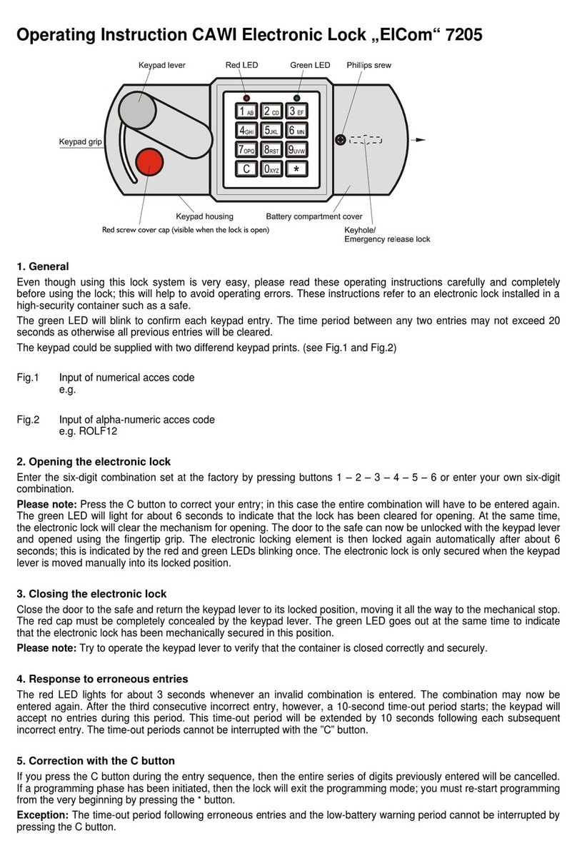
89
1-ügelig – Automatik
Gangügel
Der Gangügel entriegelt und önet automatisch,
während der Standügel verschlossen bleibt.
1-ügelig – Dauerentriegelt
Gangügel
Der Gangügel ist dauerhaft entriegelt, während
der Standügel verschlossen bleibt.
2-ügelig – Automatik
Gang- und Standügel
Sowohl der Gangügel, als auch der Standügel
werden automatisch ent- und verriegelt. Die
Schließfolgeregelung bestimmt den Schließvor-
gang des Türelements und führt die Türen in die
vorgeschriebene Verschlusslage.
2-ügelig – Dauerentriegelt
Gang- und Standügel
Sowohl der Gangügel, als auch der Standügel
werden automatisch entriegelt und verbleiben
dauerhaft entriegelt.
4. Funktionsbeschreibung
Dauerbe-
stromt
Keine Brand- und
Rauchschutzzulassung
Dauerbe-
stromt
Keine Brand- und
Rauchschutzzulassung

10 11

10 11
Assembly instructions for
emergency exit lock case systeQ-S 7665
with motorised module systeQ-S 765M
Functional unit
Motorised module
systeQ-S 765M
emergency exit lock
case systeQ-S 7665
Mortise lock with panic exit
hardware modes of operation
systeQ-S-ESC
systeQ-S-SL-ESC

12 13
Index
1. General information
1.1 Product description...................................……………………......................…......13
1.2 Intended use...................................……………………......................…................13
1.3 Functionality……………………………………………...............................…….........13
1.4 Connection diagram.......................................................................................14-15
1.5 Technical data......................................................................................................15
2. Assembly of the functional unit
2.1 Bar cutting..........................................……........................................…………....16
2.2 Installation and mounting instructions ……....…….............................…….....…. 17
3. Setting options...................................................................................................18
4. Functional description.......................................................................................19

12 13
1. General information
1.1 Product description
Emergency exit lock cases formortise locks with panic exit hardware modes of operation.
Certied as per EN179, EN 1125 and EN 12209.
1.2 Intended use
The mentioned emergency exit lock cases are approved for their intended use exclusively:
Maximum dimensions of active leaf and passive leaf: 3500mm x 1600mm (h) x (w), max. 400kg per leaf.
Approved temperature range: -25°C to +70°C
Supply voltage: 100W Supply voltage: 24V DC ±10%
1.3 Functionality
The motor module systeQ-S 765M is hung and connected above the emergency exit lock case
systeQ-S 7665. Via control inputs, the motor unlocks the door as single leaf or double leaf. After an ad-
justable period of time the door will be locked again. A control via door opener buttons, motion detectors, or
other systems are also possible, ( incl. the integration with swing door drives ).
If the control inputs are permanently supplied with electricity, the motor remains in the unlocked position
(only if permanently unlocked function has been activated). This means that the latch and bolt ejector in
the lock case remain pushed out; the lock in the active leave does not engage. Additionally, the upper and
the lower locking bar at the emergency exit lock case are in the closed position (double leaf).
If the permanently unlocked function is switched o, permanently energising the inputs is of no use.
The conditions of the door are captured electronically via integrated sensors. In case of a power blackout,
the latch and bolt ejectors as well as the locking bar in the lock case are detached.
A mechanical unlocking via the rotating movement of the follower (panic bars, panic knob/handle) is possib-
le at any time. The mechanical panic function is priority switched on and always guaranteed the function.
The following modications can be performed through a pushbutton:
- The acoustic signal can be switched on and o
- The unlocking period can be adjusted
- The permanently unlocked function can be specied
In combination with swing door drives, dierent connection options exist:
- The motor-operated lock case receives the opening signals and passes these on to the swing door
drives.
- The opening signals come to the revolving door drives. The motor-operated lock case is
connected to the swing door drives as a “slave“ and receives the opening signals.
- Both components are controlled in parallel and function independently.
When needed a upstreamed circuitry takes over the control.

14 15
Pos Color Meaning Remark
1 brown/green +24V Supply voltage
2 white/green +24V //
3 red/blue GND, 0V //
4 pink/grey GND, 0V //
5 purple Malfunctionmessage OC output
6 black single leaf open OC output
7 red A RS485
8 blue open, single leaf Optocoupler input
9 pink B RS485
10 grey double leaf open Optocoupler input
11 yellow door double leaf open OC output
12 green GND Dead bolt monitoring device (optional)
13 brown Vcc (optional) Latch bolt monitoring device (optional)
14 white GND Reference lock case (optional)
1.4 Connection diagram

14 15
Inputs: - Open, single leaf (wire optocoupler input against „chassis“ ground)
- Open, dual-leaf (wire optocoupler input against „chassis ground“)
Outputs: - Single leaf open (open collector, max. 30V, 0.1A switches against „chassis ground“)
- Dual-leaf open (open collector, max. 30V, 0.1A switches against „chassis ground“)
- Malfunction (open collector, max. 30V, 0.1A switches against „chassis ground“)
The power supply may only be performed by an electrical engineering specialist. When
connecting to 230V, there is danger of life. The power supply unit must be a power source
with limited output in accordance with EN60950. The output current must not exceed 5A.
Electrical and electronic components comply with the CE standards CE compliance in
accordance with 2014/30/EU EN 61000-6-1 EMC basic standard for immunity to interference
EN 61000-6-3 EMC basic standard for emitted interference EN 60950 Device safety.
1.5 Technical data
Nominal voltage: 24V
Power consumption: 4A max.
Stand-by: 50mA
Inputs: optically decoupled
Outputs: Open collector max. 30V, 0.1A
Cable diameter: 6.5mm
Cable type: LIYY 14x0.14 mm²
Cable length: 10m
Coupling function: Operating current, currentlessly decoupled
Unlocking period: 4s pre-set, adjustable
Acoustic signal function: switchable
Interface: RS 485 optional
A power supply is necessary, 24V/DC 100W, regulated.
The maximum cable length (system cable) from the lock to the junction box must not exceed 10m.
Otherwise, the cable diameters must be adjusted to avoid a drop in voltage.

16 17
2. Assembly of the functional unit
2.1 Bar cutting
BL = Bar legth
Figure 1:
The respective lock case is manufactured for the (right) backset dimension.
The adapter plate is factory mounted with the motorised module.
Backset Backset bridge Explanation
35-45 mm – The motor module is screwed to the lock
forend directly
50-60 mm 1 backset bridge is installed between the
forend and the motor unit
65-75 mm 2 backset bridge is installed between the
forend and the motor unit
80-85 mm 3 backset bridge is installed between the
forend and the motor unit
35-45 Backset
50-60 Backset
65-75 Backset
80-90 Backset
Inactive leaf:
285mm
9650 L = L1 + 25mm
BL
Art.No.
Active leaf:
L = Lo + 42mm
9648
BL
Art.No.
255,5mm
9647 L = Lu + 57mm
BL
Art.No.
Inactive leaf:
L = Lo + 42mm
9648
BL
Art.No.
255,5mm
9647 L = Lu + 57mm
BL
Art.No.
1
2
Figure 1
4685
9648
systeQ-S
765M
Lu
Lo
systeQ-S
7665
9647
9653
9651
6658
6668
6678
7668
7678
7688
Lu
Lo
9647
9653
9651
4685
9648
4686
9650
658Z
668Z
678Z
768Z
778Z
788Z
L1
1 2
systeQ-S-
ESC
systeQ-S-
SL-ESC
systeQ-S-
ESC
systeQ-S-
SL-ESC
systeQ-S
7665
systeQ-S
765M

16 17
Figure 3:
The cable routing leads away the cable bundle.
from the coupling rods. It can be utilised on
both sides.
For this purpose, the 14-pin connector is
clipped into the front receptacle of the
cable guide. Subsequently, the cable guide
is pushed into the rear receptacle. For this,
the cable should be slightly twisted.
Cable guide
Figure 3
if necessary
cable tie
285mm
9650 L = L1 + 25mm
L = Lo + 42mm
9648
255,5mm
9647 L = Lu + 57mm
Figure 2:
Twist the lock case into the bottom milled groove and xate it with the forend screws (1+2).
Twist the motor module into the upper milled groove while hooking it into the lock case in the process (3),
and xating it with the forend screws (4).
Now you can check for optimal seating and
also carry out a function test. Finally, place the
blind fore-end on and xate it (5).
4
5
2
1
3
Figure 2
10
24
18
10
76
204
232
456
476
10
20
2.2 Installation and mounting instructions

18 19
3. Setting options
Acoustic signal setting:
- The acustic signals are set via the pushbuttons behind the forend:
The acoustic signal can be switched on and o. “O” is preset. To change the status, actuate the pushbutton
1 x briey. The conrmation of the adjustments takes place through an acoustic double signal.
Permanently unlocked function
- The permanently unlocked function can be switched on and o. “o” is preset. The motorised lock case
is only approved in this delivery condition for re and smoke doors. To change the status, actuate the
pushbutton 1 x longer, until the second signal is sounded. The conrmation of the adjustments takes place
through an acoustic double signal. The newly adjusted state must be checked subsequently. For this, the
respective input must be energised permanently. Also see the warning below.
Adjusting the unlocking period:
- The unlocking period can be adjusted. 4 seconds are preset. After this period, the latch and bolt ejectors
as well as the locking rods (in case of double leaf unlocking) are released again (The locking rods are
now being held by the switch lock). To adjust the unlocking period, the pushbutton must be kept actuated for
the desired period of time (at least 3 seconds). An acoustic signal is sounded for each second held. The
change is conrmed by the sounding of a double signal. You have the option to set durations between
3 and 255 seconds.
Disposal
Since the motorised module
systeQ765M contains electronic
components, it must be disposed
of separately.
Warning notes:
The motor unit is delivered with the permanently
unlocked function switched o. Only in this state
the product is approved for re and smoke protection.
If the permanently unlocked function switched on,
the motorised lock case should not be installed in
re doors or smoke doors. Fire doors or smoke
doors must be self-locking. This is not the case if the
permanently unlocked function is switched on. The
lockable latch cannot engage in the lock case forend.
Fire doors or smoke doors must be self-locking.
This is not the case if the permanently unlocked
function is switched on.
As soon as the lock has been connected correctly and
is operational, this is signalled by a green LED visible lit
in the lock’s forend.
Adjustment options via the
pushbuttons. The centre blind
forend must be removed, which
is covering the adjustment
opening.

18 19
Single leaf – Automatic
Active leaf
The active leaf unlatches and opens automatically
while the inactive leaf remains closed.
Single leaf – Permanently unlocked
Active leaf
The active leaf is unlatched over a long term
while the inactive leaf remains closed.
Double leaf – Automatic
Active and inactive leaf
Both the active leaf and the inactive leaf are
automatically unlocked and locked. The closing
sequence control determines the locking process
of the door elements, ensuring that the doors are
locked as required.
Double leaf – Permanently unlocked
Active and inactive leaf
Both the active leaf and the inactive leaf are
automatically unlocked and remain permanently
unlocked.
4. Functional description
Continuously
energised
No approval for
smoke and re doors
Continuously
energised
No approval for
smoke and re doors

70 40 564 01 01.19
This manual suits for next models
1
Table of contents
Languages:
Other Esco Lock manuals