Technical Data
CPCI-HD/2 Hardware Manual • Doc.-No.: C.2318.21 / Rev. 1.0 Page 7 of 13
2. Technical Data
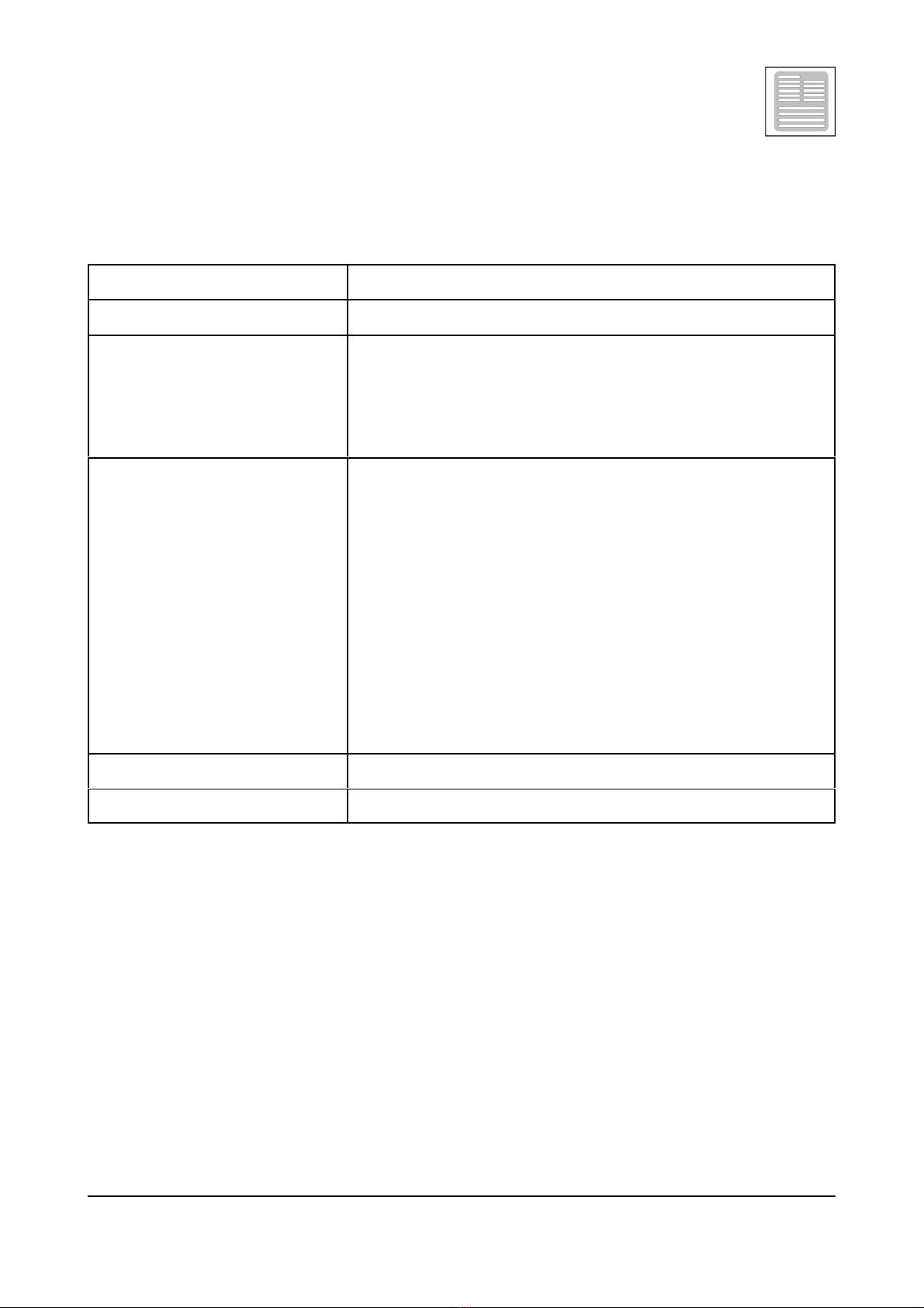
2.1 General Technical Data
Temperature range 0...50 /C ambient temperature
Humidity max. 90%, non-condensing
Power supply
via CompactPCI-Bus,
nominal supply voltages: 3.3 V / 80 mA
5 V / 1.5 A (starting current,
typ. with 40 GB HDD),
5 V / 0.6 A (quiescent current)
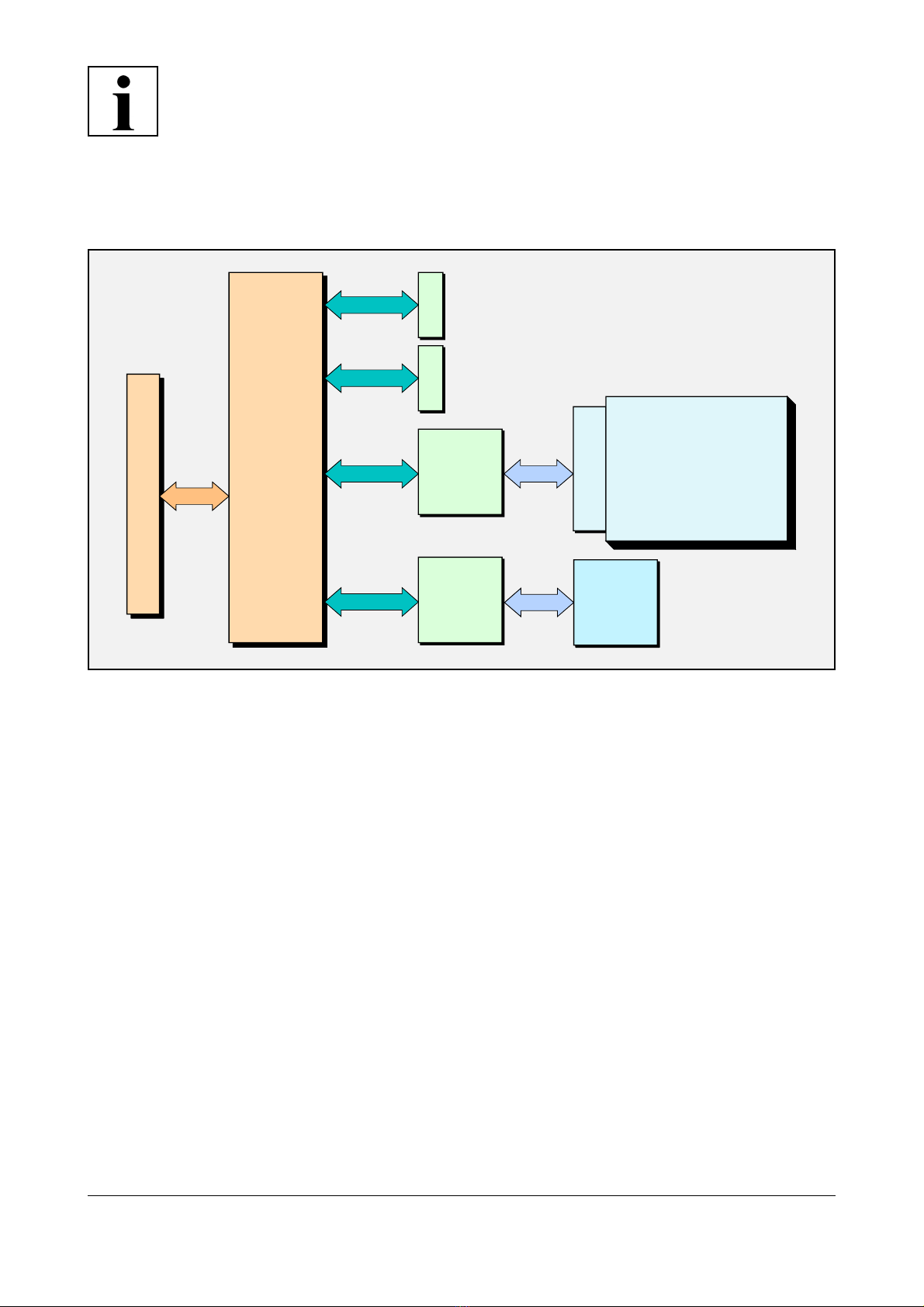
Connectors
X0 (7-pin Serial ATA-connector, angled )
- SATA0, interface for external drive
X1 (7-pin Serial ATA-connector, angled )
- SATA1, interface for external drive
X2 (44-pin IDE-connector, male)
- interface for local HDD, 2 mm grid
X3 (50-pin AMP-C-FLASH male connector) -
CompactFlash slot
X100 (132-pin male connector) -
CompactPCI-board connector
test- and programming only:
X4 (8-pin micro plug) - JTAG, Debug
Dimension 3 U, 4 HP
Weight approx. 150 g without HDD