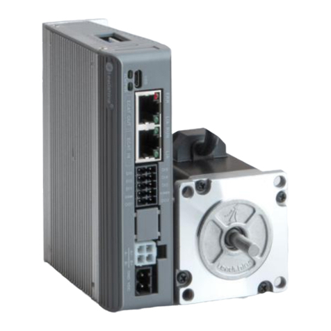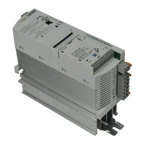
CL42T(V4.1) Closed-Loop Stepper Driver
Table of Content
1.
Features...........................................................................................................................................................................1
2.
Specifications..................................................................................................................................................................1
2.1
Electrical Specifications........................................................................................................................................ 1
2.2
Environment............................................................................................................................................................ 1
2.3
Mechanical Specifications.................................................................................................................................... 2
3.
Connections and LED Indication................................................................................................................................. 3
3.1
P1 – Control and Digital Output Connections....................................................................................................3
3.2
P2 - Encoder Signals Input Connector............................................................................................................... 4
3.3
P3 - Motor Connector............................................................................................................................................ 4
3.4
P4 - Power Connector........................................................................................................................................... 4
3.5
P5 – Tuning Port.....................................................................................................................................................4
3.6
LED Status Lights.................................................................................................................................................. 5
3.7
Switches.................................................................................................................................................................. 5
4.
Power Supply Selection................................................................................................................................................ 5
4.1
Power Supply Sharing...........................................................................................................................................5
4.2
Selecting Supply Voltage...................................................................................................................................... 5
5.
Switch Configurations.....................................................................................................................................................6
5.1
S1 - Rotating Switch Configurations................................................................................................................... 6
5.2
S2 - DIP Switch Configurations............................................................................................................................6
5.2.1
Micro Step (SW1-SW4)..............................................................................................................................7
5.2.2
Mode Setting (SW5 - SW8)....................................................................................................................... 7
5.3
S3 - Selector Switch Configurations....................................................................................................................7
6.
Typical Connection.........................................................................................................................................................8
6.1
Digital Input Connection........................................................................................................................................ 8
6.2
Fault Output Connection....................................................................................................................................... 9
6.3
Brake Output Connection......................................................................................................................................9
7.
Sequence Chart of Control Signals.............................................................................................................................9
8.
Fault Protections & Troubleshooting.........................................................................................................................10


