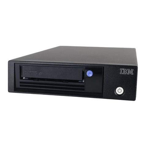
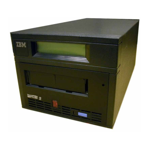
IBM TS22 Series User manual

IBM TS22xx Tape Drives
IBM

© Copyright IBM Corp. 2022.
US Government Users Restricted Rights - Use, duplication or disclosure restricted by GSA ADP Schedule Contract with IBM Corp.

Tables of Contents
IBM TS22xx Tape Drives
Introduction
Drive features
Front panels of the drives
Rear panel of the drive
Drive performance
Media compatibility
Media optimization
Speed matching
Channel calibration
Data cartridge capacity scaling
Encryption
Inhibiting firmware down-leveling
SAS interface
Supported servers and operating systems
Supported device drivers
Ethernet port
IBM Spectrum Archive
Specifications
Installing
Avoiding drive damage
Unpacking the drive
Verifying the shipment
Installing the rack mount kit (optional)
Inspecting the power cord and outlet
Positioning the tape drive
Installing the SAS host adapter card (if required)
Connecting the SAS interface cable
Connecting power
Running drive diagnostics
Installing device drivers
Configuring the tape drive to a server/host
Updating firmware
Registering for My Support
Managing
Operating modes
Power button
Single-character display (SCD)
Status lights
Unload button
Inserting a tape cartridge
Removing a tape cartridge
Mid-tape recovery
Cleaning the drive head
Cleaning the tape drive
Tape Drive Status web page
Diagnostic and maintenance functions
Entering Maintenance mode
Exiting Maintenance mode
Function code 0: Maintenance mode
Function code 1: Run drive diagnostics
Function code 2: Update drive firmware from FMR tape
Function code 3: Create FMR tape
Function code 4: Force a drive dump
Function code 5: Copy drive dump
Function code 6: Run host interface wrap test
Function code 7: Run RS-422 wrap test
Function code 8: Unmake FMR tape
Function code 9: Display error code log
Function code A: Clear error code log
Function code C: Insert cartridge into tape drive
Function code E: Test cartridge & media
Function code F: Write performance test
Function code H: Test head
Function code J: Fast read/write test
Function code L: Load/unload test
Function code P: Post Error Reporting enabled
Function code U: Post Error Reporting disabled
Tape drive diagnostic and maintenance web page
Troubleshooting
Procedure 1: Determining firmware level and capturing drive dump
1
1
2
3
3
3
4
4
5
5
5
5
6
6
6
7
7
7
7
7
8
8
8
9
9
9
9
9
10
10
10
10
10
11
12
12
12
12
13
14
14
15
15
15
16
16
17
18
18
19
19
19
19
20
20
20
21
21
21
22
22
22
22
23
23
23
24
24
24
25
26

Procedure 2: Inspecting a cartridge for damage
Procedure 3: Checking SAS host connections
Procedure 4: Verifying host interface communications
Resolving problems reported by the server
Resolving media-related problems
Pre-call checklist
Replacing the tape drive
LTO media
Data cartridges
Cartridge Compatibility
LTO type M cartridge (M8)
Capacity Scaling
WORM (Write Once, Read Many) cartridges
WORM media
Data security on WORM media
WORM media errors
WORM requirements
Cleaning cartridge
Cartridge memory chip (LTO-CM)
Bar code label
Guidelines for bar code labels
Write-Protect switch
Handling the cartridges
Providing training
Ensuring proper packaging
Proper acclimation and environmental conditions
Completing a thorough inspection
Handling the cartridge carefully
Examples of cartridge problems
Repositioning or reattaching a leader pin
Repositioning a leader pin
Reattaching a leader pin
Environmental and shipping specifications for tape cartridges
Disposing of tape cartridges
Ordering media supplies
Ordering bar code labels
Reference
TapeAlert flags
Ordering optional features, replacement parts, and power cords
Installing a 19-inch rack mount kit (optional)
Rack safety
Verify kit contents
Tools required
Installing the shelf
Removing the shelf from the rack
Information for trained service personnel
Removing the internal drive
Step 1. Removing the cover
Step 2. Removing the internal drive
Manually removing a tape cartridge
Before you begin
Recommended tools
Beginning procedure
Tape spooled off supply reel
Tape pulled from or broken near leader pin
Tape broken in mid-tape
Tape tangled along tape path
No apparent failure or damage to tape
Replacing the internal drive
Step 1. Replacing the internal drive
Step 2. Replacing the cover
Accessibility
Notices
Trademarks
Terms and conditions for product documentation
Homologation statement
Electromagnetic compatibility notices
Australia and New Zealand Notice
Canada Notice
European Community and Morocco Notice
Germany Notice
Japan Electronics and Information Technology Industries Association (JEITA) Notice
27
27
27
28
28
28
28
29
30
31
32
32
32
32
33
33
33
33
33
34
35
35
35
36
36
37
37
37
38
38
38
39
42
42
42
45
45
45
45
49
49
51
51
52
52
52
53
53
53
54
55
55
55
56
56
57
58
59
60
60
60
60
61
62
62
63
63
63
63
64
64
64

Japan Voluntary Control Council for Interference (VCCI) Notice
Korea Notice
People's Republic of China Notice
Russia Notice
Taiwan Notice
United Kingdom Notice
United States Federal Communications Commission (FCC) Notice
Safety and environmental notices
Attention notices
Possible safety hazards
Class I laser product
Acclimation
Performing the safety inspection procedure
Rack safety
Power cords
Glossary
Publications
IBM LTO Tape Drives
Overview
Drive information
Full-height drives
Half-height drives
Drive features
Media optimization
Recommended access order (RAO) open function
Archive mode unthread
Speed matching
Channel calibration
Data cartridge capacity scaling
Encryption
Front panel of the drive
Media compatibility
Planning
Acclimation
Location requirements
Host requirements
SAS interface
Fibre Channel interface
Compatible configurations
Supported device drivers
Application software
Managing
Updating drive firmware
Maintenance functions
Entering Maintenance mode
Exiting Maintenance mode
Function code 0: Maintenance mode
Function code 1: Run drive diagnostics
Function code 2: Update drive firmware from FMR tape
Function code 3: Create FMR tape
Function code 4: Force a drive dump
Function code 5: Copy drive dump
Function code 6: Run host interface wrap test
Function code 7: Run RS-422 wrap test
Function code 8: Unmake FMR tape
Function code 9: Display error code log
Function code A: Clear error code log
Function code C: Insert cartridge into tape drive
Function code E: Test cartridge & media
Function code F: Write performance test
Function code H: Test head
Function code J: Fast read/write test
Function code L: Load/unload test
Function code P: Post Error Reporting enabled
Function code U: Post Error Reporting disabled
Troubleshooting
How the drive reports problems
Running drive tests
Downloading drive log
Troubleshooting guide
65
65
65
65
65
66
66
66
66
68
68
69
69
69
71
71
80
81
82
82
82
83
83
84
84
84
84
85
85
85
86
86
87
87
88
90
90
90
90
91
91
91
91
92
93
93
93
94
94
94
95
95
95
96
96
96
96
97
97
97
97
98
98
99
99
99
99
99
100
100

Pre-call checklist
Contacting IBM technical support
IBM Tape Diagnostic tool (ITDT)
Drive error codes and messages
SCD dot
Status lights
TapeAlert flags supported by the drive
Sense data
Reference
LTO media
Data cartridges
Cartridge compatibility
LTO type M cartridge (M8)
Capacity Scaling
WORM (Write Once, Read Many) cartridges
WORM media
Data security on WORM media
WORM media errors
WORM requirements
Cleaning cartridge
Cartridge memory chip (LTO-CM)
Bar code label
Guidelines for bar code labels
Write-Protect switch
Handling the cartridges
Providing training
Ensuring proper packaging
Proper acclimation and environmental conditions
Completing a thorough inspection
Handling the cartridge carefully
Examples of cartridge problems
Repositioning or reattaching a leader pin
Repositioning a leader pin
Reattaching a leader pin
Environmental and shipping specifications for tape cartridges
Disposing of tape cartridges
Ordering media supplies
Ordering bar code labels
Manually removing a tape cartridge
Before you begin
Recommended tools
Beginning procedure
Tape spooled off supply reel
Tape pulled from or broken near leader pin
Tape broken in mid-tape
Tape tangled along tape path
No apparent failure or damage to tape
Accessibility
Notices
Trademarks
Terms and conditions for knowledge centers
Homologation statement
Electromagnetic compatibility notices
Australia and New Zealand Notice
Canada Notice
European Community and Morocco Notice
Germany Notice
Japan Electronics and Information Technology Industries Association (JEITA) Notice
Japan Voluntary Control Council for Interference (VCCI) Notice
Korea Notice
People's Republic of China Notice
Russia Notice
Taiwan Notice
United Kingdom Notice
United States Federal Communications Commission (FCC) Notice
Safety and environmental notices
Attention notices
Possible safety hazards
Class I laser product
Acclimation
102
103
103
103
107
107
108
111
111
111
112
113
113
113
113
114
114
114
114
114
115
115
116
116
116
117
117
118
118
118
119
119
119
120
123
123
123
126
126
127
127
127
127
128
129
130
130
132
132
133
134
134
135
135
135
135
135
136
136
136
137
137
137
137
137
138
138
140
140
87

IBM TS22xx Tape Drives
Welcome to the IBM® TS22xx tape drives documentation, where you can find information about how to install, maintain, and use the IBM LTO tape drives.
Last updated: December 4, 2020.
Introduction
Installing
This is a customer setup unit. It is the customer's responsibility to install this product.
Managing
Troubleshooting
Use the information in this section to troubleshoot any issues with your tape drive and configuration.
LTO media
LTO media is available in various types. Ensure you choose a media type that your drive supports.
Reference
This section provides information about the Parts list, publications, and other reference documentation.
Notices
This information was developed for products and services that are offered in the US. This material might be available from IBM in other languages. However,
you might be required to own a copy of the product or product version in that language in order to access it.
Glossary
Publications
Getting started
Introduction
Planning
Installing
Managing
Common tasks
../TS2260/con_LTOdrive_diagnosticfunctions.html
../TS2260/con_LTOdrive_cartridges_handling.html
../TS2260/ltodrv_cleaning.html
../TS2260/tsk_2340_replacingTD.html
Troubleshooting and support
Troubleshooting
IBM tape storage support
IBM Support home page
More information
TapeAlert flags
Ordering optional features, replacement parts, and power cords
Information for trained service personnel
Publications
IBM Community (Community platform)
IBM Support content (Product support)
IBM Spectrum Archive Single Drive Edition documentation
Redbooks home page
©Copyright IBM Corporation 2017-2021. Last updated: 2022-04-07
Introduction
The IBM® TS2290 (3580 H9S) Tape Drive is a high-performance, high-capacity data-storage device that is designed to back up and restore open systems
applications. It is the ninth generation in the Ultrium series of products. It is available with a Serial Attached SCSI interface (SAS). This model incorporates the
Linear Tape-Open (LTO) IBM Ultrium 9 Half Height tape drive..
IBM TS22xx Tape Drives 1

For older generations of the IBM 3580 (TS2260 and earlier), refer to the IBM Publications website to find the appropriate Setup. Operator, and Service Guides
online.
Select United States for the country/region/language to begin (for English), then click >.
Click SEARCH FOR PUBLICATIONS.
In the Search on box, type the generation of TS22xx tape drive (such as TS2270), then click Start search.
Drive features
The many features of the TS2290 tape drive
Front panels of the drives
The front panel of the half-height tape drive houses the power button, unload button, and some indicator lights.
Rear panel of the drive
The rear panel of the drive - element description
Drive performance
If you run applications that are highly dependent on tape-processing speed, take advantage of the significant performance improvements that are provided
by this tape drive.
Media compatibility
The TS2290 tape drive uses the IBM LTO Ultrium TB data cartridge and is compatible with the cartridges of its predecessor, the IBM Ultrium Tape Drive
Generation 8.
Media optimization
Media optimization is a new feature for the LTO9 tape drive with L9/LZ media.
Speed matching
To improve system performance, the drive uses a technique that is called speed matching to dynamically adjust its native (uncompressed) data rate to the
slower data rate of a server.
Channel calibration
System performance is optimized by channel calibration.
Data cartridge capacity scaling
Capacity scaling enables faster random access to data.
Encryption
Inhibiting firmware down-leveling
The drive provides the capability to prevent loading and installing drive microcode by way of a Field Microcode Replace (FMR) tape if the firmware level
contained in the FMR tape is older than the code level already installed.
SAS interface
The half height drives can have a dual port 12 Gbps SAS (Serial Attached SCSI) host interface. See con_2340_performance.html#performance__drv_info to
find out SAS speeds of different generations drives.
Supported servers and operating systems
Supported device drivers
Device drivers enable the drive to interact with various servers. IBM provides device driver support for its various LTO tape drives.
Ethernet port
The LTO tape drive has a single 1 Gbps Ethernet port on the rear panel, with an RJ45 connector.
IBM Spectrum Archive
The IBM Spectrum® Archive linear tape file system (previously known as LTFS) is a file system that works with LTO Generation tape technology to access
data stored on an IBM tape cartridge.
Specifications
Specifications for the tape drive.
Drive features
The many features of the TS2290 tape drive
The drive offers these features:
Native storage capacity of up to 18 TB per cartridge (45 TB at 2.5:1 compression) with Ultrium 9 cartridges
Native storage capacity of up to 12 TB per cartridge (30 TB at 2.5:1 compression) with Ultrium 8 cartridges
Maximum native data transfer rate of up to 300 MB per second
Maximum burst data transfer rate of 1200 MB/s for SAS and 800 MB/s for Fibre Channel
2IBM TS22xx Tape Drives

Half height form factor
Support for WORM (Write Once Read Many) on WORM cartridge types
Read and write compatibility with Ultrium 8 and Ultrium 9 media
1 GB read-and-write cache
Support for encryption on Ultrium 8 and Ultrium 9 tape cartridges
Single Character Display (SCD) operator panel
Ready, Fault, and Encryption status lights
Maintenance Mode functions
1 Gbps Ethernet port for drive status and service
IBM Spectrum® Archive (LTFS) capable
Front panels of the drives
The front panel of the half-height tape drive houses the power button, unload button, and some indicator lights.
Figure 1. Half-height front panel element descriptions
1 Cartridge unload button 5 Single-character display (SCD)
2 Ready light (Green) 6 SCD dot
3 Encryption light (white) 7 Drive power button
4 Fault light (amber)
Rear panel of the drive
The rear panel of the drive - element description
Figure 1. Drive rear panel with dual SAS ports
1 Power receptacle
2 Fan vent
3 SAS connectors
4 Ethernet connector (for drive status and service only)
Drive performance
If you run applications that are highly dependent on tape-processing speed, take advantage of the significant performance improvements that are provided by this
tape drive.
Table 1. Drive information and performance specification
Generation LTO 9 LTO 8 LTO 7 LTO 6 LTO 5
Inquiry ULT3580-HH9
ULTRIUM-HH9
ULT3580-HH8
ULTRIUM-HH8
ULT3580-HH7
ULTRIUM-HH7
ULT3580-HH6
ULTRIUM-HH6
ULT3580-HH5
ULTRIUM-HH5
IBM TS22xx Tape Drives 3

Generation LTO 9 LTO 8 LTO 7 LTO 6 LTO 5
Interface (speed) FC (8 Gb)
SAS (12 Gb)
FC (8 Gb)
SAS (6 Gb)
FC (8 Gb)
SAS (6 Gb)
FC (8 Gb)
SAS (6 Gb)
FC (8 Gb)
SAS (6 Gb)
Native data rate 300 Mb/s (L9)
300 Mb/s (L8)
300 Mb/s (L8)
300 Mb/s (M8)
300 Mb/s (L7)
300 Mb/s (L7)
160 Mb/s (L6)
140 Mb/s (L5)
160 Mb/s (L6)
140 Mb/s (L5)
120 Mb/s (L4)
140 Mb/s (L5)
120 Mb/s (L4)
80 Mb/s (L3)
Sustained data rate (L6, L7, L8 and L9 compressed at 2.5:1
compression; L5 and earlier compressed at 2:1compression)
FC
700 Mb/s (L9)
700 Mb/s (L8)
SAS
720 Mb/s (L9)
720 Mb/s (L8)
FC
700 Mb/s (L8)
700 Mb/s (M8)
700 Mb/s (L7)
SAS
600 Mb/s (L8)
540 Mb/s (M8)
500 Mb/s (L7)
FC
700 Mb/s (L7)
400 Mb/s (L6)
280 Mb/s (L5)
SAS
500 Mb/s (L7)
400 Mb/s (L6)
280 Mb/s (L5)
FC and SAS
400 Mb/s (L6)
280 Mb/s (L5)
240 Mb/s (L4)
FC and SAS
280 Mb/s (L5)
240 Mb/s (L4)
160 Mb/s (L3)
Burst data rate
800 Mb/s FC
1200 Mb/s SAS
800 Mb/s FC
600 Mb/s SAS
800 Mb/s FC
600 Mb/s SAS
800 Mb/s FC
600 Mb/s SAS
800 Mb/s FC
600 Mb/s SAS
Nominal load-to-ready time 16 seconds 15 seconds 15 seconds 12 seconds 12 seconds
-Initialized tape 16 seconds NA NA NA NA
-Uninitialized tape240-132 minutes NA NA NA NA
Nominal unload time 56 seconds 24 seconds 20 seconds 17 seconds 17 seconds
Average space record time from load point 65 seconds 59 seconds 56 seconds 62 seconds 60 seconds
Average rewind time (REWIND command) 62 seconds 59 seconds 60 seconds NA NA
Average rewind time (part of UNLOAD command, dependent on mount activity)
Less than 5 Gb of contiguous data transferred 62 seconds 59 seconds 60 seconds NA NA
5 Gb to 50 Gb of contiguous data transferred 124 seconds 59 seconds 60 seconds NA NA
All other types of mount activity 186 seconds 59 seconds 60 seconds NA NA
1 By using the built-in data-compression capability of the tape drive, greater data rates than the native data transfer rate are achieved. However, the actual
throughput is a function of many components, such as the host system processor, disk data rate, block size, data compression ratio, SAS bus capabilities, and
system or application software.
2 Cartridge initialization time can vary. See Media optimization for more information.
Remember:
All sustained data rates depend on the capabilities of the interconnect.
Drive performance varies with media generation and drive interface (SAS/FC).
Media compatibility
The TS2290 tape drive uses the IBM® LTO Ultrium TB data cartridge and is compatible with the cartridges of its predecessor, the IBM Ultrium Tape Drive Generation
8.
The drive reads tapes that are written by other licensed Ultrium 8 and 9 drives, and writes to tapes that are read by other licensed Ultrium 8 and 9 drives.
Ultrium 9 is able to read and write Ultrium 8 cartridges, and thus can interchange data with Ultrium 8 tape drives. However, the Ultrium 9 drive allows an Ultrium 8
cartridge to be written only at the LTO Generation 8 operating point (12 TB). M8 cartridges are not supported. Unlike prior generations, read-only support for 2nd
generation media such as LTO 7 is no longer supported. See Cartridge Compatibility.
Note: See Data cartridges for information about cartridge types and capacities.
Media optimization
Media optimization is a new feature for the LTO9 tape drive with L9/LZ media.
The increased number of tracks used to write data on tape requires greater precision. Media optimization creates a referenced calibration for each cartridge that
enables the tape drive’s intelligent alignment to optimize data placement. LTO-9 media optimization enhances LTO tape long-term media durability.
It is important to consider when media optimization will be performed:
Media optimization will be performed on first load of L9/LZ media during initialization.
Recommendation is to perform first load in the location of deployment, which should be in a stable environment that meets the recommended
environmental specification .
Media optimization is a one-time operation that can be completed on any drive in the environment, enabling the media to be used across all tape drives
without further optimization.
Other considerations for media optimization:
4IBM TS22xx Tape Drives

Media optimization averages 40 minutes per first load of a cartridge to a tape drive. Although most media optimizations will complete within 60 minutes
some media optimizations may take up to 2 hours.
Interruption of the process is not recommended.
A different mount will not necessarily improve the time to complete the one-time optimization.
An update to software may be required. Contact your software application provider for more details. Customized software, not provided as a standard market
product, may require modification to ensure the software can handle the extended first mount time. For additional details, review the detailed section of the IBM
LTO SCSI Reference.
Speed matching
To improve system performance, the drive uses a technique that is called speed matching to dynamically adjust its native (uncompressed) data rate to the slower
data rate of a server.
With speed matching, the drive operates at different speeds when it is reading or writing the Ultrium 8 or later cartridge format. Native data rates are shown in the
table.
Table 1. Performance parameters
Ultrium Generation Media
Generation 9 media Generation 8 media Generation 7 media
Speed matching data rates (MB/sec) 408*365.0*306.0
385*341.0*287.52
366*318.0*268.56
347*306.4 250.66
325*273.0 231.86
305*249.5 213.06
284 226.0 194.26
263 203.0 175.46
244 180.0 157.67
223 157.5 138.52
203 135.0 120.11
177 112.0 101.46
*Full height drives only. Maximum native date rate for full height drives is 400 MB/s, and for half height drives is 300 MB/s.
If the server's net (compressed) data rate is between two of the preceding native data rates, the drive calculates the appropriate data rate at which to operate.
Speed matching dramatically reduces backhitch, the condition that occurs when a tape stops, reverses, and restarts motion. A backhitch is usually the result of a
mismatch between the data rates of the server and the drive.
Channel calibration
System performance is optimized by channel calibration.
System performance is further optimized by a feature that is called channel calibration, in which the drive automatically customizes each read/write data channel
to compensate for variations in such things as the recording channel 's transfer function, the media, and characteristics of the drive head.
Data cartridge capacity scaling
Capacity scaling enables faster random access to data.
The SET CAPACITY SCSI command enables a customer to capacity scale a data cartridge to enable faster random access. As an example, a customer can capacity
scale a data cartridge to 20% of its normal length that improves the average access time by almost a factor of 5. However, it also reduces the native capacity of the
tape to 1.2 TB.
Encryption
Data encryption is supported by LTO Ultrium 4 and later data cartridges only.
The IBM® LTO tape drive supports host Application Managed Encryption (AME), with T10 encryption methods.
The encryption-enabled drive contains the necessary hardware and firmware to encrypt and decrypt host tape application data. Encryption policy and encryption
keys are provided by the host application. A drive digital certificate is installed at manufacturing time. Each drive receives a unique serial number and certificate.
The T10 Application can validate each drive instance by checking the drive's digital certificate.
IBM TS22xx Tape Drives 5

Application-managed encryption is supported on AIX®, Windows Server, Linux®, and Solaris. Encryption requires current device drivers, available on the website
https://www-945.ibm.com/support/fixcentral.
For details, see the IBM Tape Device Drivers Encryption Support documentation, and the IBM LTO Ultrium Tape Drive SCSI Reference documentation.
Inhibiting firmware down-leveling
The drive provides the capability to prevent loading and installing drive microcode by way of a Field Microcode Replace (FMR) tape if the firmware level contained in
the FMR tape is older than the code level already installed.
This option is controlled by the host application. No checking is done if the firmware level is loaded by way of the host interface or the library interface.
SAS interface
The half height drives can have a dual port 12 Gbps SAS (Serial Attached SCSI) host interface. See con_2340_performance.html#performance__drv_info to find
out SAS speeds of different generations drives.
A drive with a SAS interface can be linked directly to controllers. SAS is a performance improvement over traditional SCSI because SAS enables multiple devices
(up to 128) of different sizes and types to be connected simultaneously with thinner and longer cables. Its full-duplex signal transmission supports up to 12.0
Gbps. In addition, SAS drives can be hot-plugged. The maximum SAS cable length that can be used to connect the host adapter to the tape drive varies depending
on the type of SAS connection. See Optional features for the maximum cable length that can be used.
SAS drives auto-negotiate speed. There are no configurable topologies thus no feature switches associated with SAS.
Physical characteristics
The drive contains a dual port, SFF-8644 SAS connector. A list of compatible cables is shown in Ordering optional features, replacement parts, and power cords.
Supported servers and software
IBM has many resources where you can check what software and servers your tape drive is compatible with.
Compatible servers and software
These attachments can change throughout the lifecycle of the product. To determine the newest attachments, or to get a comprehensive list of compatible
software, do one of the following actions.
For a list of compatible software, operating systems, and servers for LTO tape drives, see https://www.ibm.com/it-infrastructure/storage/tape.
Note:
1. IBM® does not provide application software with the drive. To order software, contact your IBM sales representative, IBM Business Partner, or an
independent software provider.
2. If you attach your drive to a server with non-IBM software, contact your software vendor for a matrix of compatible hardware, software, firmware
revisions, and adapters.
For complete IBM storage interoperability information for the tape drive in a storage area network (SAN) configuration, see the IBM® Interoperation Center
(SSIC) at http://www-03.ibm.com/systems/support/storage/ssic/interoperability.wss. The SSIC has details on supported operating systems, servers,
switches, and adapters.
Note: Dependent on the use of Random or Sequential Mode, the drive might require an HBA with multiple LUN supports. Also, multiple LUN supports must be
enabled on the host computer. When multiple LUN supports are not enabled, the host computer can see the tape drive, but not the library.
Supported device drivers
IBM provides device driver support for the LTO tape drives.
IBM maintains the current levels of device drivers and driver documentation on the web. Go to http://www.ibm.com/support/fixcentral and follow the steps to
access this material.
1. From the Fix Central web page, choose the Select Product tab, select System Storage from the Product Group list.
2. Select Tape Systems from the System Storage list.
3. Select Tape drivers and software from the Tape systems list.
4. Select Tape device drivers from the Tape drivers and software list.
5. Select the appropriate operating system from the Platform list and click Continue.
6. Select the appropriate driver from the list.
The IBM Tape Device Drivers and Diagnostic Tool User's Guide can be found at
https://www.ibm.com/support/knowledgecenter/STAKKZ/dd_iug_kc/DD_kchome.html.
6IBM TS22xx Tape Drives

Supported device drivers
Device drivers enable the drive to interact with various servers. IBM provides device driver support for its various LTO tape drives.
To properly install an IBM® device driver (if required), refer to the IBM Tape Device Drivers Installation and User's Guide. For applications that use other device
drivers, see the application's documentation to determine which drivers to use.
IBM maintains the levels of device drivers and driver documentation for the drive on the Internet. You can access this material at
http://www.ibm.com/support/fixcentral.
Note: If you do not have Internet access and you need information about device drivers, contact your sales representative.
Note: The device driver for System i® servers is included in the OS/400® operating system.
Ethernet port
The LTO tape drive has a single 1 Gbps Ethernet port on the rear panel, with an RJ45 connector.
The Default IP address is 169.254.0.3, but the drive's IP address can be changed as needed. Refer to ITDT to see how to this change is made.
The Ethernet port is used only for monitoring drive status and servicing the drive, not for data transmission.
Important: The Ethernet port is for Service only. Do not connect the customer network to Service ports.
IBM Spectrum Archive
The IBM Spectrum® Archive linear tape file system (previously known as LTFS) is a file system that works with LTO Generation tape technology to access data
stored on an IBM® tape cartridge.
IBM Spectrum Archive uses the file system’s format and resources of the operating system (OS) on which it is running to graphically display the contents of a tape
cartridge in the OS’s graphical user interface (GUI) format; typically a folder/tree structure. With the host operating system’s graphical File Manager, reading data on
an LTO tape cartridge is as easy as dragging and dropping. Users can run any application that is designed for disk files against tape data without concern for the fact
that the data is physically stored on tape.
Specifications
Specifications for the tape drive.
Specifications for tape cartridges are given in Environmental and shipping specifications for tape cartridges.
Table 1. Specifications
Physical Specifications
Specification Dimensions
Width 213 mm (8.4 in.)
Length 332 mm (13.1 in.)
Height 58 mm (2.3 in.)
Weight 4.3 kg (9.4 lbs.)
Power Specifications
AC line voltage 100 - 240 Vac
Line frequency 50 - 60 Hz, auto-ranging
Line current at 100 Vac 0.48 A
Line current at 240 Vac 0.20 A
Other Specifications
Maximum altitude 3048 m (10,000 ft)
Maximum altitude for shipping 12192 m (40,000 ft)
Environmental Specifications
Environmental Factor Operating Storage Shipping
Temperature 10 - 38°C (50 - 100°F) -40 to 60°C (-40 to 140°F) -40 to 60°C (-40 to 140°F)
Relative humidity 20 - 80% 10 - 90% 10 - 90%
Maximum wet bulb temperature 26°C (79°F) Non-condensing Non-condensing
Installing
This is a customer setup unit. It is the customer's responsibility to install this product.
IBM TS22xx Tape Drives 7

Installation involves the following steps.
Avoiding drive damage
To avoid static electricity damage when the drive is handled, use the following precautions.
Unpacking the drive
Unpack the drive and store the packaging for future moves or shipping.
Verifying the shipment
Ensure that the following items are included in the shipment.
Installing the rack mount kit (optional)
If you need to install a rack mount kit, follow these procedures.
Inspecting the power cord and outlet
Inspect the power cord and receptacle, and check that the outlets are properly grounded.
Positioning the tape drive
Position the unit so it is convenient to the server.
Installing the SAS host adapter card (if required)
If no other devices are attached to your server, a SAS host adapter might need to be installed in the server.
Connecting the SAS interface cable
Each tape drive is required to have a dedicated bus to the initiator, referred to as point-to-point connection. SAS architecture does not support multiple tape
drives connected to a single host adapter port. The maximum SAS cable length that can be used to connect the host adapter to the tape drive varies
depending on the type of SAS connection. See Optional features for the maximum cable length that can be used.
Connecting power
Steps to install and connect a power cable to your unit.
Running drive diagnostics
Run the Standalone Diagnostic procedure.
Installing device drivers
A device driver is firmware that enables the tape drive to interact with various servers.
Configuring the tape drive to a server/host
Steps for configuring your tape drive to a server/host.
Updating firmware
It is the customer's responsibility to ensure that this drive has the current firmware. Several options are available for updating drive firmware.
Registering for My Support
My Support registration provides email notification when new firmware levels are updated and available for download and installation.
Avoiding drive damage
To avoid static electricity damage when the drive is handled, use the following precautions.
Limit your movement. Movement can cause static electricity to build around you.
Always handle the drive carefully. Never touch exposed circuitry.
Prevent others from touching the drive.
Before you unpack and install the drive into an enclosure, touch its static-protective packaging to an unpainted metal surface on the enclosure for at least 2
seconds. This procedure reduces static electricity in the packaging and your body.
When possible, remove the drive from its static-protective packaging and install it directly into an enclosure without setting it down. When this action is not
possible, place the drive 's packaging on a smooth, level surface and place the drive on the packaging.
Do not place the drive on the cover of the enclosure or on any other metal surface.
Unpacking the drive
Unpack the drive and store the packaging for future moves or shipping.
Attention: If you return the unit for service, ship it in its original or equivalent packing material, or the warranty might be invalidated.
1. Inspect the unit for shipping damage. If there is damage, do not install the unit, and report the damage immediately. Contact your place of purchase.
2. Locate the label on the bottom panel of the unit with the machine type, model number, and serial number of the unit. Make a note of these numbers and
store them in an easily accessible place. If you must contact Technical Support, you are asked for these numbers.
Verifying the shipment
Ensure that the following items are included in the shipment.
Power cord (For the appropriate cord for your country or region, see Ordering optional features, replacement parts, and power cords.)
IBM® Ultrium Cleaning Cartridge
Single-connector SAS HD wrap tool (optional)
Rack Mount kit (optional)
IBM Half Height LTO Tape drive (SAS) Installation Quick Reference, GC27-2276-03
IBM documentation for TS22xx Tape Drives along with translated warranty information, and translated Safety and Environmental notices. See Safety and
Environmental notices.
SAS cables are not part of the shipment and must be ordered separately.
8IBM TS22xx Tape Drives

Installing the rack mount kit (optional)
If you need to install a rack mount kit, follow these procedures.
Refer to Installing a 19-inch rack mount kit (optional). If you did not order the optional kit, proceed to Inspecting the power cord and outlet.
If you ordered a 24-inch rack mount kit, refer to the installation instructions included in the kit.
Inspecting the power cord and outlet
Inspect the power cord and receptacle, and check that the outlets are properly grounded.
1. Inspect the power cord plug to ensure that it matches the power receptacle. If it does not match, see Power cords to determine the appropriate power cord.
2. Ensure that all associated electrical outlets are properly grounded and that the circuit breaker is turned on.
DANGER
An electrical outlet that is not correctly wired could place hazardous voltage on metal parts of the system or the devices that attach to the
system. It is the responsibility of the customer to ensure that the outlet is correctly wired and grounded to prevent an electrical shock. (D004)
Positioning the tape drive
Position the unit so it is convenient to the server.
The only restrictions are the length of the power cord and the length of the cable to the server. Recommended locations are:
Away from high-traffic areas, especially if the floor is carpeted
Out of printer or copy rooms to avoid toner and paper dust. Do not store paper supplies next to any unit.
Away from moving air, such as doorways, open windows, fans, and air conditioners
Off the floor
In a horizontal position
Where the tape cartridge can be easily inserted
The unit should not be stacked. Do not place anything on top of the unit.
Installing the SAS host adapter card (if required)
If no other devices are attached to your server, a SAS host adapter might need to be installed in the server.
To install an adapter, refer to the instructions that accompany it, also to the section about host adapter installation in your server's documentation. For a list of
supported adapters and required interposers, visit the web at http://www.ibm.com/storage/lto.
Connecting the SAS interface cable
Each tape drive is required to have a dedicated bus to the initiator, referred to as point-to-point connection. SAS architecture does not support multiple tape drives
connected to a single host adapter port. The maximum SAS cable length that can be used to connect the host adapter to the tape drive varies depending on the
type of SAS connection. See Optional features for the maximum cable length that can be used.
To connect the cable:
1. Ensure that the tape drive is powered OFF.
2. Since there are several types of SAS connectors, verify that the SAS cable has the correct connectors for the SAS host adapter and for the tape drive.
3. The tape drive has two SAS ports and can be connected to two servers. Refer to the appropriate figure that represents your configuration for cabling
information (see Figure 1 or Figure 2). Then, connect the SAS cables to SAS host adapters and to the tape drive as shown.
Figure 1. Example of connecting one SAS device to the server
1 Tape drive 4 SAS host adapter
2 SAS connector 5 Server
3 SAS cable
IBM TS22xx Tape Drives 9

Figure 2. Example of connecting the SAS device to two servers
1 Tape drive 4 SAS host adapter
2 SAS connector 5 Servers
3 SAS cables
4. Ensure that the host adapter and the server are configured correctly for a SAS bus operation. Refer to the host adapter and server documentation for
instructions.
5. If the power cord is already installed, turn power to the tape drive ON.
Connecting power
Steps to install and connect a power cable to your unit.
1. If the power cord is already installed, skip to step 3.
2. Plug the power cord into the rear panel (see Figure 1), then plug the other end into a grounded electrical outlet.
3. Power on the unit by pressing Power. The POST runs, which check all hardware except the drive head. During the POST, the Single-character Display (SCD)
flashes several segmented characters. Each segmented character represents a test that is completed during the POST. When the POST finishes, the SCD
momentarily lights all segmented characters and then goes blank.
Running drive diagnostics
Run the Standalone Diagnostic procedure.
See Function code 1: Run drive diagnostics for instructions.
Installing device drivers
A device driver is firmware that enables the tape drive to interact with various servers.
Refer to Supported device drivers for instructions on downloading the current device drivers. If you intend to use the tape drive with a commercial software
application, refer to that application's installation instructions to install the device driver and configure the tape drive.
If you do not intend to use the tape drive with a commercial software application, refer to the IBM® Ultrium Device Drivers Installation and User's Guide.
Configuring the tape drive to a server/host
Steps for configuring your tape drive to a server/host.
1. Ensure that the tape drive is powered on.
2. To configure the tape drive, refer to the documentation for your server/host and application software.
Updating firmware
It is the customer's responsibility to ensure that this drive has the current firmware. Several options are available for updating drive firmware.
Attention: When firmware is updated, do not power off the drive until the update is complete, or the firmware might be lost.
Periodically check for updated levels of drive firmware by going to the web at http://www.ibm.com/support/fixcentral. The drive firmware can be downloaded from
this website. Update drive firmware with:
The host interface
The ITDT tool
A field microcode replacement (FMR) tape cartridge
10 IBM TS22xx Tape Drives

The Ethernet interface
For instructions on obtaining a new firmware image, go to http://www.ibm.com/support/fixcentral. To update the firmware, refer to the following sections.
Updating firmware through the host interface
When drive firmware is updated with the host interface, the procedure varies depending on whether your server uses an IBM® tape device driver or a non-IBM tape
device driver (such as a driver from Sun, Hewlett-Packard, or Microsoft).
For instructions about updating firmware from a server that uses an IBM tape device driver, refer to the IBM Tape Device Drivers and Diagnostic Tool User's Guide.
To update firmware from a server that uses a non-IBM tape device driver, refer to the documentation for that device driver.
ITDT firmware update, dump retrieval and library/drive test tool
ITDT is a tool with multiple functional capability and is a quick, convenient, and efficient method for both drive and library firmware updates. As a note, both drive
and library memory dump retrievals can be completed by the tool as well.
Some of the capabilities of this tool:
Firmware update capability to all IBM LTO Tape Drive and Tape Library products.
The tool does not require any special device drivers.
The tool is available for most major platforms (Windows, AIX®, Solaris, Linux®, HP-UX, i5/OS).
The tool can upload drive and library dump files.
The tool's primary function is thoroughly testing a drive. However, if the library is online to the server/host where the tool resides, ITDT communicates with
the drive through the library to load and unload a test cartridge, exercising some library functions.
The tool scans the host bus and finds and displays for selection of all IBM LTO devices. The tool does not display and allow for selection of any non-IBM
device.
Each function has a "Help" selection that explains the required syntax and a brief explanation of the particular function.
A readme text file is posted with the .exe for a thorough explanation of initial tool download information from the web and an explanation of tool capabilities.
For more information about tool usage, see the ITDT readme text file. For more information about the ITDT site, see http://www.ibm.com/support/fixcentral.
The tool is available in two editions, ITDT-SE (Standard Edition) and ITDT-GE (Graphical Edition). Information about the ITDT editions can be found at
http://www.ibm.com/support/fixcentral.
Updating the firmware with an FMR tape cartridge
Attention: A SAS drive requires a SAS firmware image. Other types of firmware images do not load on the SAS drive.
To update the drive 's firmware from an FMR tape cartridge:
1. Create an FMR tape (see Function code 3: Create FMR tape). A single FMR tape can be used to update multiple drives if the drives are the same drive type
(for example, LTO 8) and host interface (for example, SAS).
2. Update the drive firmware (see Function code 2: Update drive firmware from FMR tape).
After the drive firmware is updated, the FMR tape can be used as a data cartridge by with the "Unmake FMR Tape" function (see Function code 8: Unmake FMR
tape).
The SCD presents a series of random characters during the firmware download and update. The SCD briefly displays , then becomes blank (not lit) when the
firmware download and update is complete and there are no errors. An error code is displayed if a firmware download or update error is detected. The Ready light
and the Fault light flash briefly during the firmware download and update. The Ready light turns on after the firmware download and update are complete.
Updating the firmware with the Ethernet port - Service only
Note: The drive uses a limited version of FTP protocol to communicate on the Ethernet interface. Use a simple, command-line FTP session, such as the DOS
command line, to communicate with the drive.
1. Obtain the current drive firmware from the web.
2. Connect an Ethernet patch cable to the drive's Ethernet interface and to a computer. To meet electromagnetic immunity requirements, a shielded Ethernet
cable is required.
3. Create an FTP session between the drive and the computer. The drive 's IP address: 169.254.0.3
4. At the user prompt, type guest and press Enter.
5. At the password prompt, press Enter. No response is needed.
6. Type bin to set the communication mode to binary.
7. Type put <firmware name> to transfer the firmware to the drive. Replace <firmware name> with the actual firmware name. The drive resets
automatically when the transfer is complete and the FTP session closes.
8. After the drive resets, the new firmware is loaded on the drive.
9. Remove the Ethernet patch cable from the drive's Ethernet interface and the computer.
Registering for My Support
My Support registration provides email notification when new firmware levels are updated and available for download and installation.
To register for My Support, visit the web at http://www.ibm.com/support/mySupport.
IBM TS22xx Tape Drives 11

Managing
The front panel display and buttons are used to operate the tape drive.
Operating modes
The tape drive functions in two modes.
Power button
The Power button is a push button that turns the tape drive on or off.
Single-character display (SCD)
The single-character display (SCD) is found on the front panel of the tape drive. The codes that are displayed provide information about drive status.
Status lights
The status lights provide information about the status of the tape drive.
Unload button
The Unload button completes several functions.
Inserting a tape cartridge
Removing a tape cartridge
Several steps for removing a tape cartridge.
Mid-tape recovery
If a reset occurs while a cartridge is loaded, the drive slowly rewinds the tape and ejects the cartridge.
Cleaning the drive head
Use an IBM Ultrium cleaning cartridge to clean the tape drive head.
Cleaning the tape drive
Tape Drive Status web page
The status of the tape drive is accessible from the tape drive’s Ethernet port. The drive status can be viewed only. The status cannot be changed from the
Tape Drive Status web page. The tape drive status is available when the drive is operating or idle (the drive must be powered on).
Diagnostic and maintenance functions
Refer to this section for information on diagnosing and maintaining your tape drives.
Tape drive diagnostic and maintenance web page
Several of the tape drive's maintenance functions are run with the tape drive's Ethernet port. These functions are the same maintenance functions that are
run with Unload on the drive's front panel.
Operating modes
The tape drive functions in two modes.
Operation mode - Functions include reading and writing data, cartridge manipulation, error reporting, and firmware updating with a field microcode
replacement (FMR) cartridge. For more information, see Status lights.
Maintenance mode - Functions include drive diagnostic, creation/unmake FMR cartridge, and drive memory dump manipulation (force to RAM, copy to tape,
copy to flash memory, and erase flash). For more information, see Diagnostic and maintenance functions.
The Unload button is used to switch between modes. For more information, see Unload button.
Power button
The Power button is a push button that turns the tape drive on or off.
The button is located on the front panel (see 7 in Front panels of the drives). When Power is in the off position, the primary electrical power within the enclosure is
still active. To remove all electrical power to the enclosure, unplug the power cord from the receptacle at the rear of the drive.
When the unit is powered-on but idle, the Ready light (2 in Front panels of the drives) is solid green. When it is completing a function, the Ready light is flashing
green.
Single-character display (SCD)
The single-character display (SCD) is found on the front panel of the tape drive. The codes that are displayed provide information about drive status.
The SCD (5 in Front panels of the drives) presents a single-character code for:
Error conditions and informational messages
Diagnostic or maintenance functions (while in maintenance mode only)
Error codes and messages lists the codes for error conditions and informational messages. If multiple errors occur, the code with the highest priority (represented
by the lowest number) displays first. When the error is corrected, the code with the next highest priority displays until no errors remain.
Diagnostic and maintenance functions lists the single-character codes that represent diagnostic or maintenance functions. To initiate a function, the unit must be in
maintenance mode.
The SCD is blank during normal operation.
12 IBM TS22xx Tape Drives

SCD dot
If a drive memory dump is present while the drive is in maintenance mode, a single dot illuminates in the lower right corner of the SCD (see 6 in Front panels of the
drives). To copy the memory dump, see Function code 5: Copy drive dump.
The SCD dot is on solid if the memory dump is in RAM memory. The SCD dot flashes if the memory dump is in flash memory.
The SCD dot turns off when you obtain a dump (by using ITDT or a SCSI command) or update the drive firmware.
Note: If the drive memory dump is stored in RAM memory (SCD dot on solid), the memory dump is lost when you turn OFF the power or reset the drive.
Status lights
The status lights provide information about the status of the tape drive.
The status lights (in Front panels of the drives) are light-emitting diodes (LEDs) that provide information about the state of the drive.
The Ready status light is green and the Fault status light is amber, and (when lit) solid or flashing. The Encryption status light is white.
Mode SCD Ready LED (green) Fault LED (amber)
Operational Blank On Off
Activity (tape movement) in Operational Mode Blank Flashing Off
Maintenance Solid character Flashing On
Executing Maintenance Selection Flashing character Off On
Error Condition Solid character Off Flashing
Power on / Reset Initialization Random segments Off On
Note: The white Encryption status light is ON when the tape drive has a cartridge that is loaded and all data on this cartridge is encrypted (excluding the label).
Applicable to LTO Ultrium 7 and later cartridges only.
Table 1 lists the conditions of the status lights and Single-character Display (SCD) and provides an explanation of what each condition means.
Table 1. Meaning of status lights and single-character display (SCD)
If the green
Ready Status
Light is...
And the amber
Fault Status
Light is...
And the
Encryption
Status Light
is...
And the SCD is... And the SCD
dot is... Meaning
Off Off Off Off Off The drive has no power or is powered off.
On Off On/Off Off Off The drive is powered on and in an idle state.
Note: If a cartridge is loaded, the white Encryption status light is
on when all the data on the cartridge is encrypted (excluding the
label). LTO Ultrium 7 and later cartridges only.
Flashing (once
per second)
Off On/Off Off Off The drive is reading from the tape, writing to the tape, rewinding
the tape, locating data on the tape, loading the tape, or unloading
the tape.
Note: The white Encryption status light is on when all the data on
the cartridge is encrypted (excluding the label). LTO Ultrium 7 and
later cartridges only.
Flashing (once
per second)
Off Off Off Off If the drive contains a cartridge during the power-on cycle, the
drive completes POST and slowly rewinds the tape. The process
might take up to 13 minutes. The light stops flashing and becomes
solid when the drive completes the recovery and is ready for a
read or write operation. To eject the cartridge, press Unload.
Off On Off Displaying an error
code or
Maintenance Mode
Function
On/Off The drive is displaying error codes from the error code log on the
SCD. For more information, see Function code 9: Display error
code log and Error codes and messages.
On/Off On/Off On/Off Displaying random
segments/
Blank/displaying
random segments/
displaying /Blank
On/Off During power-on, or a drive reset, the drive front panel displays
drive progress as follows:
1. SCD displays random segments (no Lights ON).
2. SCD displays random segments (Ready light ON).
3. SCD displays random segments (Fault light ON).
4. SCD displays [8] (Ready, Fault, Encryption, and SCD dot
lights ON).
5. SCD goes blank (Ready light ON) after a successful power-
on or reset.
If an error is detected during the power-on or reset, the tape drive
posts an error code to the SCD. To determine the error, locate the
code in Error codes and messages.
Off On Off On/Off The drive is entering or exiting from Maintenance mode. For more
information, see Function code 0: Maintenance mode.
IBM TS22xx Tape Drives 13
Table of contents
Other IBM DC Drive manuals

IBM
IBM 9040-MR9 User manual

IBM
IBM ThinkPad 73P3279 User manual

IBM
IBM TS2290 User manual

IBM
IBM OPTIONS Zip 100MB IDE User manual

IBM
IBM ThinkPad 73P3315 User manual

IBM
IBM 9348 Operating and installation instructions

IBM
IBM ThinkPad 22P7028 User manual

IBM
IBM L5X User manual

IBM
IBM ThinkPad 73P3297 User manual

IBM
IBM Ultrium Internal Tape Drive T200 User manual
Popular DC Drive manuals by other brands

OEZ
OEZ RP-BC-CK30 Instructions for use

National Instruments
National Instruments NI MID-7602 USER GUIDE AND SPECIFICATIONS

Festo
Festo FDG-...-ZR-RF Series operating instructions

Danfoss
Danfoss vlt aqua manual

SEW-Eurodrive
SEW-Eurodrive MOVITRAC 31C operating instructions

WEG
WEG Easy Drive CFW10 user guide