manuals.online logo
Brands
  1. Home
  2. •
  3. Brands
  4. •
  5. EsiWelma
  6. •
  7. Gas Detector
  8. •
  9. EsiWelma Sensigas URD20SW User manual

EsiWelma Sensigas URD20SW User manual

EsiWelma Srl URD20SW_en - rev. 1 CO
2
gas detectors – URD20SW
24/11/2011 Gas detection systems for industrial environments 1/4
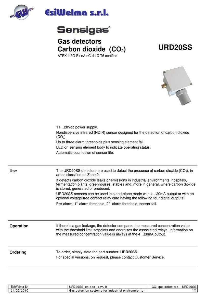
Carbon Dioxide
(CO2) gas detectors
IP30 Protection Rating
URD20SW
Use The URD20SW detectors can be used to measure the concentration of Carbon
Dioxide and to control transmitters or actuating devices where there are abnormal
concentrations well below the gas hazard threshold.
The URD20SW detectors can also be used to monitor Carbon Dioxide as an indication
of the quality of the air in hotels, offices, exhibition centres, shops, restaurants,
schools, conference rooms, cinemas, theatres and ventilation systems in general.
Operation The URD20SW detectors are designed to interface with the UCE1 and UCE4 control
units and, more generally, with any 4...20mA or 0...10V (in addition 0…20mA or
2…10Vdc) control unit or data acquisition systems.
Ordering To order, simply state the part number as follows: URD20SW
Technical
specifications
Type of sensor
NDIR (non-dispersive infrared)
Detectable Gas Carbon dioxide (CO2)
Power supply 24Vac (50/60Hz±10%), 24Vdc
Max power consumption 1.6W
Measuring range 0÷20.000ppm (other ranges on request)
Measuring precision (@25°C) ± 100ppm + 3% of the readout
Measuring stability 2% on full scale, for the lifetime of the sensor
Measuring linearity 1% of full scale
Warm-up time < 2m
Stabilization time < 2m, 10m for maximum accuracy
Response time < 2m (T90)
Average operational life of Sensor
(in air) 15 years from installation
Analog output 4…20mA or 0…10Vdc (0…20mA or 2…10Vdc)
Max detectable area about 100 m2(approximate; for larger areas
install several devices at suitable distances
from each other)
Ambient Temperature (°C)
- Operating
- Storage
0…50°C
-40…70°C
Ambient humidity (%RH)
- Operating
-
Storage
0...95% RH (non condensing)
Protection Rating IP30
Enclosure ABS/PC UL94-V0 flame retardant
Dimensions and weight See dedicated section
Options & Accessories
Gas calibration Kit TUL40.. See installation and commissioning chapter
EC Conformity
EMC Directives / Standards
LVD Directives / Standards
EMC 2004/108/EC
EN 61000-6-1 + EN 61000-6-3
Not applicable
EsiWelma Srl URD20SW_en - rev. 1 CO
2
gas detectors – URD20SW
24/11/2011 Gas detection systems for industrial environments 2/4
Mechanical
installation
I
nstallation
guidelines
Installation
procedure
Carefully read the instructions and electronic connection diagrams in this document and follow
them to the letter. Keep this document in a safe place for future consultation.
The device must be installed by qualified technicians.
Since Carbon Dioxide is heavier than air, it will be concentrated close to the floor.
Take into consideration the following specific installation guidelines, as well as the above
instructions, for location of the detectors.
The detectors must be installed:
1. where accidental gas leakages are possible
2. at least 1.5m away from heat sources or from vent holes
3. not in spaces where ventilation is poor and where gas pockets may form
4. away from hindrances to natural gas flow
5. away from equipment that may leak gas during normal operations
6. in environments with a temperature range of -20°C to 50°C and relative humidity below 90% (non-
condensing)
7. Disconnect equipment from the power supply when mounting and dismantling detectors.
Install the detector as follows:
Use the tip of a screwdriver to lightly push down the upper tabs of the detector until the wall
mounting plate is separated from the actual detector body. See Fig 1, steps 1 to 4.
Fig 1
Fig 2
Fix the mounting plate to the wall with the screws
supplied or a suitable wall bracket, or to the recessed
mounting cabinet used.
See Fig 2 for the fixing template.
Connect the wiring; make sure the cables pass through
the wall-mounting plate.
Remount the detector body onto the wall-mounting plate;
make sure the tabs click into place. See Fig 3, steps 5 to
7.
Fig. 3
3
4
1
2
5
67
60. 00
45. 00
55. 00
28. 00
3. 00
4. 50
8. 00
EsiWelma Srl URD20SW_en - rev. 1 CO
2
gas detectors – URD20SW
24/11/2011 Gas detection systems for industrial environments 3/4
Electrical
Installation
Terminal board
and electrical
connections
Cabling:
Configuration:
Selecting the
analog output type
CAUTION: Make sure the device power supply is off before cabling and configuration
operations.
Install the sensor in compliance with laws in force.
Depending on the connecting distance, use at least 3-core cable, min. diameter 0.75mm2up to
100m, 1mm2up to 200m, 1.5mm2up to 500m.
Use shielded cable where there is a risk of electromagnetic interference.
In order to change the configuration, switch off the power supply, input the new settings by J1,
S1 and S2 jumpers as shown in the diagram, then power-up again; in particular:
The default setting for the sensor output is 4...20mA signal.
Select the analog output type by J1, S1 and S2 jumpers
Jumpers J2, J3, J4 and J5 are just for manufacture test with default of disconnection.
Please don’t change it!
Jumper S1-S2 Jumper J1 Analog Output
Lower two pins blocked disconnected 0…10Vdc
Upper two pins blocked disconnected 0…20mA
Lower two pins blocked Connected 2…10Vdc
Upper two pins blocked Connected 4…20mA (default)
Checklist after
mechanical and
electrical
installation
The sensors are factory calibrated so they normally do not require any other calibration once
installed. Still, after installation, an operational check of the sensors is recommended.
The detector will enter a 2-minute warm-up phase after power-up.
After this time, the sensor will switch to normal operating mode, but it will take about 10
minutes before it reaches top performance level.
Carry out an operational response test using a CO2gas cylinder with nozzle; release a small
amount of gas close to the grille below and control the variation of the output current / output
voltage.
EsiWelma Srl URD20SW_en - rev. 1 CO
2
gas detectors – URD20SW
24/11/2011 Gas detection systems for industrial environments 4/4
Maintenance
Routine
Corrective
Decommissioning
A sensor functional test should be carried out every three-six months.
Routine maintenance involves repeating the same tests as set forth in “checklist after
mechanical and electrical installation”.
If any abnormalities are found during routine sensor maintenance, return the sensor concerned
to the supplier / installer, who in turn will send it back to the manufacturer.
Remove power from the sensor, disconnect all wiring and conduits and dismount the housing
from all the blocking systems.
Warranty Warranty on EsiWelma products is valid for 12 months from installation date and no longer
than 24 months from manufacturing date on the product. Installation data, stamp and
signature on the data sheet filled in by the installer will be considered proof for warranty.
A copy of the warranty data sheet (at the end of this document) must be sent when returning
the product under warranty.
Dimensions and
weight
Dimensions (HxWxD):
102mm×90mm×40mm
. Weight: 0.12 Kg
Installation data
To be filled in by Installer Installer's stamp and
signature
Installation site:
Part number:
Manufacturing date:
Installation date:
Replacement date:
60. 00
45. 00
55. 00
28. 00
3. 00
4. 50
8. 00

Other EsiWelma Gas Detector manuals

EsiWelma Sensigas URD20SE User manual

EsiWelma

EsiWelma Sensigas URD20SE User manual

EsiWelma Sensigas URD20SL User manual

EsiWelma

EsiWelma Sensigas URD20SL User manual

EsiWelma Sensigas UR 13/A Series User manual

EsiWelma

EsiWelma Sensigas UR 13/A Series User manual

EsiWelma Sensigas URS40SL User manual

EsiWelma

EsiWelma Sensigas URS40SL User manual

EsiWelma Sensigas ESN I Series User manual

EsiWelma

EsiWelma Sensigas ESN I Series User manual

EsiWelma Sensigas ESN.0.P Series User manual

EsiWelma

EsiWelma Sensigas ESN.0.P Series User manual

EsiWelma Sensigas UCE11 User manual

EsiWelma

EsiWelma Sensigas UCE11 User manual

EsiWelma Sensigas URD40SE User manual

EsiWelma

EsiWelma Sensigas URD40SE User manual

EsiWelma Sensigas URS40SI User manual

EsiWelma

EsiWelma Sensigas URS40SI User manual

EsiWelma Sensigas ESN26.C Instruction manual

EsiWelma

EsiWelma Sensigas ESN26.C Instruction manual

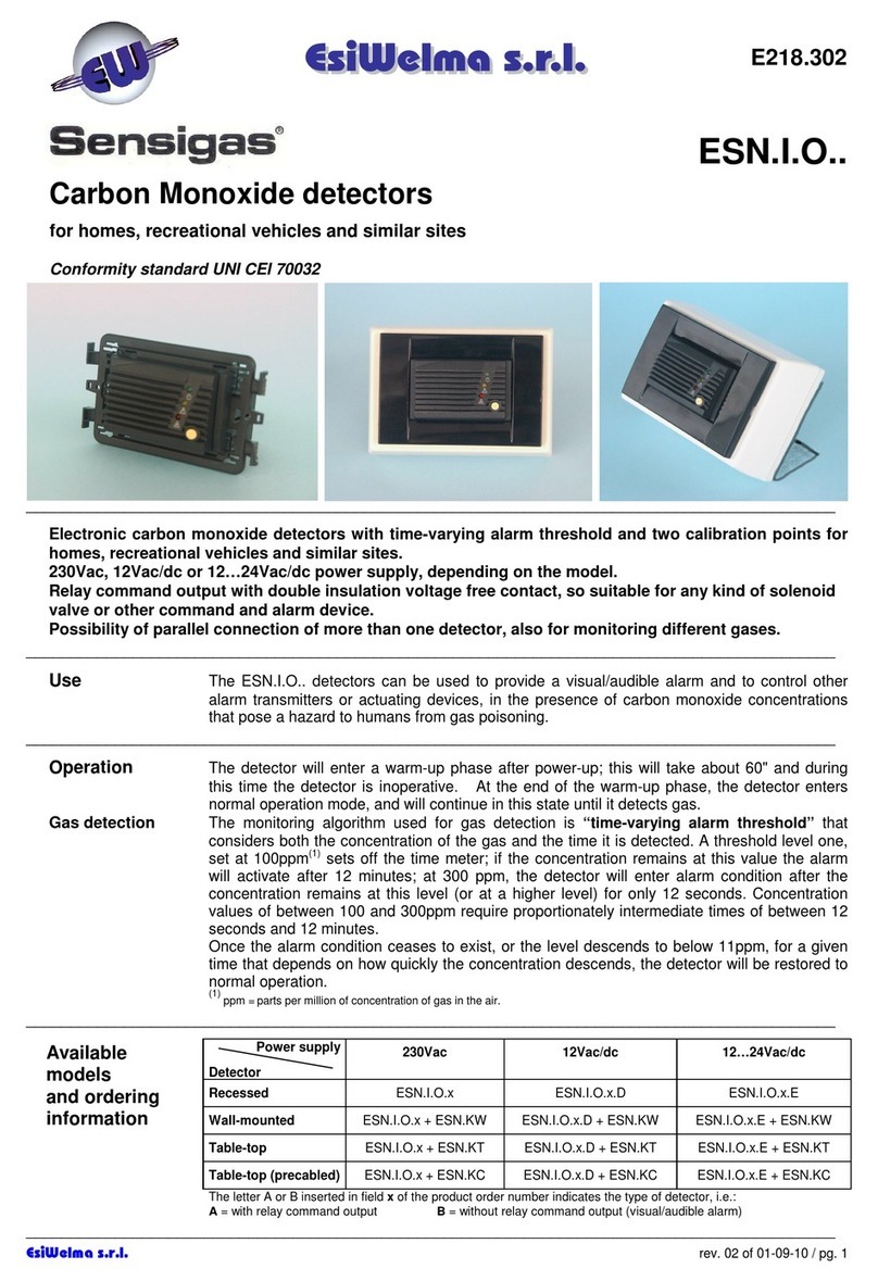
EsiWelma Sensigas ESN.I.O Series User manual

EsiWelma

EsiWelma Sensigas ESN.I.O Series User manual

EsiWelma Sensigas URD20SS User manual

EsiWelma

EsiWelma Sensigas URD20SS User manual

EsiWelma Sensigas URS20SL User manual

EsiWelma

EsiWelma Sensigas URS20SL User manual

Popular Gas Detector manuals by other brands

Tecnogas 12030 Operation manual

Tecnogas

Tecnogas 12030 Operation manual

Honeywell HON COCON 13 Operator's manual

Honeywell

Honeywell HON COCON 13 Operator's manual

Honeywell FS20X Series user manual

Honeywell

Honeywell FS20X Series user manual

Duomo HHGAS quick start guide

Duomo

Duomo HHGAS quick start guide

Alecto COA1910 manual

Alecto

Alecto COA1910 manual

New Cosmos Electric KD-12 instruction manual

New Cosmos Electric

New Cosmos Electric KD-12 instruction manual

Gas Detection GDA 3160 operating manual

Gas Detection

Gas Detection GDA 3160 operating manual

Xtrails VESDA ECO installation instructions

Xtrails

Xtrails VESDA ECO installation instructions

ATI Technologies GasSens A14 O & M Manual

ATI Technologies

ATI Technologies GasSens A14 O & M Manual

TELEDYNE OLDHAM SIMTRONICS iTRANS 2 user manual

TELEDYNE OLDHAM SIMTRONICS

TELEDYNE OLDHAM SIMTRONICS iTRANS 2 user manual

AKO AKOGAS AKO-576410 instructions

AKO

AKO AKOGAS AKO-576410 instructions

Riken Keiki 9000 Series operating manual

Riken Keiki

Riken Keiki 9000 Series operating manual

DEGA NS III LCD instruction manual

DEGA

DEGA NS III LCD instruction manual

CWSI 350 manual

CWSI

CWSI 350 manual

GDS Corp GASMAX II + GDS-IR Operation and maintenance manual

GDS Corp

GDS Corp GASMAX II + GDS-IR Operation and maintenance manual

RKI Instruments GD-70D Series operating manual

RKI Instruments

RKI Instruments GD-70D Series operating manual

mru 400GD user manual

mru

mru 400GD user manual

Riken Keiki GD-F88Di operating manual

Riken Keiki

Riken Keiki GD-F88Di operating manual

manuals.online logo
manuals.online logoBrands
  • About & Mission
  • Contact us
  • Privacy Policy
  • Terms and Conditions

Copyright 2025 Manuals.Online. All Rights Reserved.