manuals.online logo
Brands
  1. Home
  2. •
  3. Brands
  4. •
  5. EsiWelma
  6. •
  7. Gas Detector
  8. •
  9. EsiWelma Sensigas URD40SE User manual

EsiWelma Sensigas URD40SE User manual

EsiWelma Srl
URD40SE - EW0526D1_en.docx
CO2gas detectors –URD40SE
16/06/2017
Gas detection systems for industrial environments
1/4
Gas detectors
Carbon dioxide (CO2)
ATEX certified (II 2G Ex d IIC T6)
URD40SE
Sssssss
11…14Vdc power supply.
Non Dispersive Infrared (NDIR) sensor designed for the detection of carbon dioxide
(CO2).
Up to three alarm thresholds plus sensing element fail.
LED on sensing element body to indicate operating status.
Automatic countdown of sensor life.
Use
The URD40SE detectors are used to detect the presence of carbon dioxide (CO2), in
areas classified as Zone 1.
It detects carbon dioxide leaks or emissions in industrial environments, hospitals,
fermentation plants, greenhouses, stables and, more in general, where carbon dioxide
is stored, generated or produced.
URD40SE detectors transmit data from a local bus connected with their Control Unit,
which acts as the master unit of the gas detection system.
Operation
If there is a gas leakage, the detector compares the measured concentration value
with the threshold limit setpoints and energises the system relays if associate.
Alarm information is transmitted to the Control Unit, which energises its own internal
relay module (MR0) and the remote Relay and Display modules depending on the
associations.
Ordering
To order, simply state the part number: URD40SE.
For special versions, on request, please contact Customer Service.
EsiWelma Srl
URD40SE - EW0526D1_en.docx
CO2gas detectors –URD40SE
16/06/2017
Gas detection systems for industrial environments
2/4
Technical
characteristics
Type of sensor
NDIR (Non Dispersive Infrared)
Detectable Gas
Carbon dioxide (CO2)
Power supply
11÷14Vdc
Max power consumption
1,6W
Measuring range
0...20,000 ppm
Precision
5% full scale, 10% readout
Repeatability
5% full scale, 10% readout
Measurement resolution
20 ppm
Microprocessor resolution
1024 points (10 bit)
Digital filter system
Kalman Filter
Watchdog
Internal
Warm-up time
< 2m
Stabilization time
< 2m
Response time
< 25s (T90)
Average Sensor life (in air)
255 weeks
Threshold limit settings
(default setting): Pre-alarm
1st threshold alarm
2nd threshold alarm
2000 ppm
4000 ppm
8000 ppm
Operating Temperature
Storage Temperature
-20 50 °C
-20 70 °C
Relative Humidity (without condensing)
-Operation
-Storage
15 90 %RH
45 75 %RH
Operating pressure (KPa)
80 110
Air speed (m/s)
6
Visual warnings
Red LED visible with detector energized
The steady LED status can be forced by
the Control Unit to identify the sensor on
the plant
Dimensions and weight
See dedicated section
Options & Accessories
TUL40.. Gas calibration kit
See installation and commissioning chapter
TUS40 Handheld terminal
for service and maintenance
See installation and commissioning chapter
CRG40 Gas collecting cone
See dedicated data sheet
PAP40 Powerful jets protection
See dedicated data sheet
ATEX markings
1370 II 2G Ex d IIC T6
BVI 07 ATEX 0032
-20°C TA+50°C
Key to marking
information
Marking in conformity with all applicable EC Directives
1370 Identification number of Notified Body involved in production control
CE marking for all equipment in conformity with Directive ATEX 2014/34/EC
II Equipment group for surface industry
2 Equipment category 2 for use in Zone 1
G Equipment intended for use in explosive gas atmosphere, caused by mixture of air
and gas, vapours, flammable mist
Ex d IIC T6 Type of protection complying with EN60079-0 and EN60079-1
BVI 07 ATEX 0032 EC-type examination certificate
-20°C TA +50°C Operating temperature range
Sensors
lifetime
Sensor average lifetime (see technical characteristics) is referred to a typical usage in a
pollution-free environment. Presence of a high concentration of pollutants can shorten the
lifetime of the sensing element.
Once the detection system starts up, it has to be supplied with energy during all the lifetime
of its sensors. Seasonal use of the detection system is not recommended.
EsiWelma Srl
URD40SE - EW0526D1_en.docx
CO2gas detectors –URD40SE
16/06/2017
Gas detection systems for industrial environments
3/4
Installation
The relative density of carbon dioxide is about one and a half times that of air, so it
tends to collect at floor level in closed, unventilated environments.
Therefore, the sensor must be installed about 30 cm above the floor level.
Take into consideration the following specific installation guidelines, as well as the
above instructions, for location of the detectors.
The detectors must be installed:
1. where accidental gas leakages are possible
2. at least 1.5m away from heat sources or from vent holes
3. not in spaces where ventilation is poor and where gas pockets may form
4. away from hindrances to natural gas flow
5. away from equipment that may leak gas during normal operations
6. in environments with a temperature range of -20°C to 50°C and relative
humidity below 90% (non-condensing)
7. Disconnect equipment from the power supply when mounting and dismantling
detectors.
Special
recommendations
CAUTION: safety is guaranteed only if cover is screwed on tight.
-Tighten the cover clockwise, and when it is screwed on, make sure that there is
no more than 0.5 mm between housing and cover. This guarantees that it is
screwed on tight. Remember to tighten the hexagon locking grub screw that fits
into the end of the cover
-Ensure compliance with the words << DO NOT OPEN WHEN ENERGISED >>,
clearly indicated on the cover. Alternatively, make the area safe before opening
the sensor cover.
Electrical installation
and configuration
Terminal board and
electrical connections
Cabling:
CAUTION: Make the area safe and ensure that the device power supply is off
before cabling and configuration operations.
Install the sensor in compliance with EN 60079-14.
ATEX certified 1“ NPT cable glands are used for cable entry, in compliance with
standards EN 60079-0 and EN 60079-1 (Ex d protection mode).
Ground the sensor using the internal grounding system.
Refer to the Control Unit manual for all cabling information (cable type and
specifications, bus topology, length of connections etc.) and configuration.
Depending on the connecting distance, use at least 4-core cable, min. diameter
0.75mm2up to 100m, 1mm2up to 200m, 1.5mm2up to 500m.
Use shielded cable where there is a risk of electromagnetic interference.
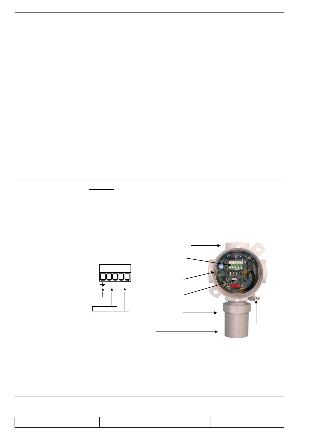
12 Vdc power supply
input
BUS input
BUS
Shield
-
+
-
+
BUS
12V
Grounding
connection
Termination
jumper
Configuration key
Cable connection
Status LED
Sensing element
Power supply
and BUS
connector
EsiWelma Srl
URD40SE - EW0526D1_en.docx
CO2gas detectors –URD40SE
16/06/2017
Gas detection systems for industrial environments
4/4
Checklist after
mechanical and
electrical installation
Before using the sensor it must be recognised by the Control Unit through an
assignment operation (refer to the manual of the aforesaid Control Unit for correct
execution).
The sensors are factory calibrated so they normally do not require any other calibration
once installed. Still, after installation, an operational check of the sensors is
recommended.
The status LED means the following:
Flashing at 2Hz NOT ASSIGNED
Flashing about every 10 sec ASSIGNED AND WORKING
Steady ALARM
Maintenance
Routine
Corrective
Decommissioning
A sensor functional test should be carried out every three-six months.
Routine maintenance involves repeating the same tests as set forth in “checklist
after mechanical and electrical installation”.
If any abnormalities are found during routine sensor maintenance, return the sensor
concerned to the supplier / installer, who in turn will send it back to the
manufacturer.
Sensors may need to be re-calibrated, using the TUL40.. gas calibration kit and the
TUS40-40 handheld terminal, which must be connected to the sensor via the
communication on the Power supply and BUS connector.
For the re-calibration procedure, see the instructions supplied with the handheld
terminal.
Remove power from the detector, disconnect all wiring and conduits and dismount
the housing from all the blocking systems.
Warranty
Warranty on EsiWelma products is valid for 12 months from installation date and
no longer than 24 months from manufacturing date on the product. Installation
data, stamp and signature on the data sheet filled in by the installer will be
considered proof for warranty.
A copy of the warranty data sheet must be sent when returning the product under
warranty.
Accessories
TUL40.. Gas calibration Kit
TUS40 Handheld terminal
CRG40 Gas collecting cone
PAP40 Powerful jets protection
Dimensions and weight
Dimensions (HxWxD): 164x100x82mm. Weight: 0.8Kg

Other EsiWelma Gas Detector manuals

EsiWelma Sensigas ESN.I.O Series User manual

EsiWelma

EsiWelma Sensigas ESN.I.O Series User manual

EsiWelma Sensigas URD20SS User manual

EsiWelma

EsiWelma Sensigas URD20SS User manual

EsiWelma Sensigas URD20SL User manual

EsiWelma

EsiWelma Sensigas URD20SL User manual

EsiWelma Sensigas URS40SI User manual

EsiWelma

EsiWelma Sensigas URS40SI User manual

EsiWelma Sensigas ESN I Series User manual

EsiWelma

EsiWelma Sensigas ESN I Series User manual

EsiWelma Sensigas UCE11 User manual

EsiWelma

EsiWelma Sensigas UCE11 User manual

EsiWelma Sensigas URD20SW User manual

EsiWelma

EsiWelma Sensigas URD20SW User manual

EsiWelma Sensigas URS20SL User manual

EsiWelma

EsiWelma Sensigas URS20SL User manual

EsiWelma Sensigas URD20SE User manual

EsiWelma

EsiWelma Sensigas URD20SE User manual

EsiWelma Sensigas URS40SL User manual

EsiWelma

EsiWelma Sensigas URS40SL User manual

EsiWelma Sensigas UR 13/A Series User manual

EsiWelma

EsiWelma Sensigas UR 13/A Series User manual

EsiWelma Sensigas ESN26.C Instruction manual

EsiWelma

EsiWelma Sensigas ESN26.C Instruction manual

EsiWelma Sensigas ESN.0.P Series User manual

EsiWelma

EsiWelma Sensigas ESN.0.P Series User manual

Popular Gas Detector manuals by other brands

Crowcon AGM 55 operating instructions

Crowcon

Crowcon AGM 55 operating instructions

BEINAT SG850 Installation and user guide

BEINAT

BEINAT SG850 Installation and user guide

Seitron BEAGLE L quick start guide

Seitron

Seitron BEAGLE L quick start guide

sauermann SGTP-CO quick start guide

sauermann

sauermann SGTP-CO quick start guide

BEINAT RGX100 quick start guide

BEINAT

BEINAT RGX100 quick start guide

Medem AGDS-MCM v2 installation instructions

Medem

Medem AGDS-MCM v2 installation instructions

Dräger X-am 7000 Instructions for use

Dräger

Dräger X-am 7000 Instructions for use

TPI 770 instruction manual

TPI

TPI 770 instruction manual

M-Power UNI 321 quick start guide

M-Power

M-Power UNI 321 quick start guide

Centech 93005 Assembly and operating instructions

Centech

Centech 93005 Assembly and operating instructions

SENSIT Technologies GAS-TRAC LZ-30 instruction manual

SENSIT Technologies

SENSIT Technologies GAS-TRAC LZ-30 instruction manual

Teledyne GT Series user manual

Teledyne

Teledyne GT Series user manual

OTIS OI-6000K NXP Series Operation manual

OTIS

OTIS OI-6000K NXP Series Operation manual

RKI Instruments VOC Pro Operator's manual

RKI Instruments

RKI Instruments VOC Pro Operator's manual

IGD TOC-750BR quick start guide

IGD

IGD TOC-750BR quick start guide

Riken Keiki SD-1DRI operating manual

Riken Keiki

Riken Keiki SD-1DRI operating manual

New Cosmos Electric PS-7-M instruction manual

New Cosmos Electric

New Cosmos Electric PS-7-M instruction manual

Geca GAMMA Series user manual

Geca

Geca GAMMA Series user manual

manuals.online logo
manuals.online logoBrands
  • About & Mission
  • Contact us
  • Privacy Policy
  • Terms and Conditions

Copyright 2025 Manuals.Online. All Rights Reserved.