EsiWelma Sensigas ESN.I.O Series User manual

EsiWelma s.r.l.
rev. 02 of 01-09-10 / pg. 1
E218.302
Carbon Monoxide detectors
for homes, recreational vehicles and similar sites
Conformity standard UNI CEI 70032
ESN.I.O..
___________________________________________________________________________________________
Electronic carbon monoxide detectors with time-varying alarm threshold and two calibration points for
homes, recreational vehicles and similar sites.
230Vac, 12Vac/dc or 12…24Vac/dc power supply, depending on the model.
Relay command output with double insulation voltage free contact, so suitable for any kind of solenoid
valve or other command and alarm device.
Possibility of parallel connection of more than one detector, also for monitoring different gases.
___________________________________________________________________________________________
Use
The ESN.I.O.. detectors can be used to provide a visual/audible alarm and to control other
alarm transmitters or actuating devices, in the presence of carbon monoxide concentrations
that pose a hazard to humans from gas poisoning.
___________________________________________________________________________________________
Operation
The detector will enter a warm-up phase after power-up; this will take about 60" and during
this time the detector is inoperative. At the end of the warm-up phase, the detector enters
normal operation mode, and will continue in this state until it detects gas.
Gas detection
The monitoring algorithm used for gas detection is “time-varying alarm threshold” that
considers both the concentration of the gas and the time it is detected. A threshold level one,
set at 100ppm
(1)
sets off the time meter; if the concentration remains at this value the alarm
will activate after 12 minutes; at 300 ppm, the detector will enter alarm condition after the
concentration remains at this level (or at a higher level) for only 12 seconds. Concentration
values of between 100 and 300ppm require proportionately intermediate times of between 12
seconds and 12 minutes.
Once the alarm condition ceases to exist, or the level descends to below 11ppm, for a given
time that depends on how quickly the concentration descends, the detector will be restored to
normal operation.
(1)
ppm =parts per million of concentration of gas in the air.
___________________________________________________________________________________________
Power supply
Detector
230Vac 12Vac/dc 12…24Vac/dc
Recessed ESN.I.O.x ESN.I.O.x.D ESN.I.O.x.E
Wall-mounted ESN.I.O.x + ESN.KW ESN.I.O.x.D + ESN.KW ESN.I.O.x.E + ESN.KW
Table-top ESN.I.O.x + ESN.KT ESN.I.O.x.D + ESN.KT ESN.I.O.x.E + ESN.KT
Table-top (precabled)
ESN.I.O.x + ESN.KC ESN.I.O.x.D + ESN.KC ESN.I.O.x.E + ESN.KC
The letter A or B inserted in field xof the product order number indicates the type of detector, i.e.:
A= with relay command output B= without relay command output (visual/audible alarm)
___________________________________________________________________________________________
Available
models
and ordering
information

EsiWelma s.r.l.
rev. 02 of 01-09-10 / pg. 2
___________________________________________________________________________________________
Outputs
Detector status
LED
GREEN
LED
YELLOW
LED
RED
BUZZER RELAY
Off OFF OFF OFF OFF OFF
Initial test for LEDs and buzzer (1s.) ON ON ON C OFF
Visualisation Firmware Version (5s.) See Table 1 OFF OFF
Sensor warm-up (60 seconds) A OFF A OFF OFF
Normal operation ON OFF OFF OFF OFF
Sensor fail (after 30 seconds) ON B OFF D ON
Alarm ON OFF B B ON
Operational test (30 seconds) Divided into two parts:
• First 25 seconds ON B B B ON
• Last 5 seconds: See Table 1 OFF ON
Key:
ON = steady on / activated / switched OFF = off / deactivated / not switched
A= the two LEDs flash alternatively at 1Hz B= the LED/Buzzer flashes/sounds every 1Hz
C= Short sound of Buzzer (Beep) D = the Buzzer sounds every 0.5Hz (slow)
Table 1
Firmware version
1
2
3
4
5
6
7
GREEN LED
ON
OFF
OFF
OFF
ON
OFF
ON
YELLOW LED
OFF
ON
ON
OFF
OFF
ON
ON
RED LED
OFF
OFF
ON
ON
ON
ON
ON
___________________________________________________________________________________________
Ensure compliance with standards in force for electrical wiring. The devices must be connected to the mains
and remain permanently powered. Omnipolar disconnection must be included in the mains.
The installation of a detector must not be a substitute for the correct installation, use and maintenance of
combustible gas appliances and equipment and for ventilation and exhaust systems for fumes.
Carefully read the instructions and electrical wiring diagrams in this document and follow them to the letter.
Keep this document in a safe place for future consultation.
The device must be installed by qualified technicians.
Installation
Since carbon monoxide weighs the same as air, it will be concentrated near the same height as the appliance
that manifests combustion defects or that is located in premises with insufficient ventilation.
Install about 2 metres (minimum 1 metre, maximum 3 metres) from the gas-operated appliance and at
standard face height of the occupants in those premises; example: 130…...170cm in a kitchen, 50...…100cm
in a bedroom.
The detector must not be installed:
• outdoors
• too close to stoves, cooking appliances and, more in general, to gas appliances
• near sinks and taps
• near exhaust hoods, windows, fans etc.
• in areas where dirt and/or dust can clog the front grille of the detector
• where the temperature or humidity exceeds the detector's operating limits
• in closed spaces (behind curtains, inside cupboards etc.).
depending on the model purchased, the detector can be mounted:
1. directly in type 503 recessed mounting box
2. screwed onto the wall with adapter ESN.KW
3. placing the device on a side table / shelf in the table-top version, using adapter ESN.KT/KC.
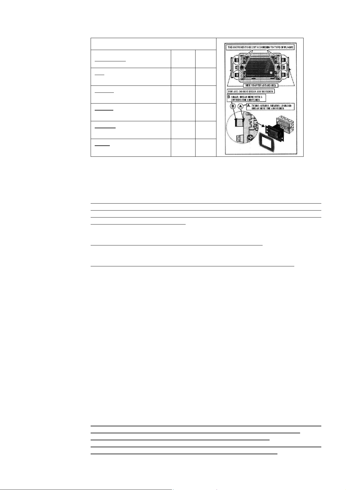
Before fixing the detector to box 503 or to adapter ESN.KW or ESN.KT/KC, the bracket needs to be adjusted to
the backing plate selected from major manufacturers of recessing equipment (see Table 2) and, if necessary,
two side adapters need to be inserted to cover the side gap created when using some plates.
After mounting is completed, fix the detector to box box 503 or to adapter ESN.KW or ESN.KT/KC and press
firmly on the front plate.
Make sure you fill in the detector replacement date on the self-adhesive label provided and stick it in a visible
position on the detector after installation.
___________________________________________________________________________________________
Operational
table
Installation and
Commissioning
EsiWelma s.r.l.
rev. 02 of 01-09-10 / pg. 3
___________________________________________________________________________________________
Table 2
Manufacturer: Side
adapters Tabs to
remove
AVE
SISTEMA 45 and BANQUISE YES None
BTICINO
Living international and Light NO A
GEWISS
PLAYBUS and PLAYBUS Young YES A
SIEMENS
DELTA FUTURA GRAPHIT YES A
VIMAR
IDEA and RONDO’ YES B
Commissioning
Power up the detector and check that all the warm-up and normal operation phases are executed.
Carry out an operational response test by pressing the button on the front to check the correct engagement of
the solenoid valve or other command and/or alarm device connected to the relay; it is advisable to repeat the
operational test at least once a year, or after a prolonged period of stoppage.
If other test methods are used instead of the one described the detector may generate different, unexpected
responses. In particular, the use of inappropriate substances or vapours (alcohol or silicon-based solvents etc.)
or in any case, high concentrations of test gases could cause permanent damage to the sensing element and
may cause the detector to operate incorrectly.
The detector needs no periodic maintenance, with the exception of the periodic operational test and its re-
placement 5 years after the installation date.
Do not tamper with or open the device: danger of electric shock and/or malfunction.
Use a wet cloth and mild detergent to periodically clean the device.
Do not use aggressive detergents like alcohol, ammonia, solvents etc.
Before cleaning the detector, switch off the system power supply to avoid the risk of electric shock.
Warning
The detector and its sensing element have been designed for ongoing use in areas where there is permanent
occupation by people, so normally pollution-free.
The presence of gases or vapours from some substances such as alcohol, silicons or solvents found in some
detergents or polishes, or from the fumes generated by cooking may cause inappropriate action of the detector
and in the long term could affect the reliability of the device.
___________________________________________________________________________________________
Carbon Monoxide (CO) is a colourless, odourless and non-irritating gas that is classified as a chemical as-
phyxiant whose toxic action is the direct result of hypoxia (oxygen deprivation) caused by exposure to it.
Carbon Monoxide is also rapidly absorbed by the lungs and is spread through the pulmonary alveolus where it
reversibly binds with the haemoglobin as carboxyhaemoglobin (COHb).
If the CO level in the air inhaled is constant, the level of COHb in the bloodstream will approach a state of equi-
librium after a few hours. Still, the speed of that equilibrium depends on a number of factors such as the indi-
vidual's state of health, but the two most important factors are the concentration of CO and the time of expo-
sure to the gas.
Typical effects of exposure to CO (at concentrations and exposure times over the ones that set off the detector)
are, in growing order of concentration and/or time:
• Slight headache, weakness and, if pregnant, possible effect on foetus
• Strong headache, nausea, loss of movement in hands
• Strong headache, irritability, confusion, loss of vision, muscle weakness, dizziness
• Convulsions and loss of consciousness
• Coma, respiratory arrest, death.
The action of the detector cannot protect individuals in particular risk categories such as people who suffer from
cardiovascular disease, hyperthyroidism, respiratory disease etc
___________________________________________________________________________________________
If an alarm goes off, stay calm, put out flames, switch off the gas or LPG cylinder at the meter, switch off all gas
heating appliances such as gas stoves etc., open doors and windows to increase the flow of fresh air.
If the alarm stops, it is necessary to find out what set it off and take consequent action.
If the alarm continues and the reason for the presence of carbon monoxide cannot be determined or eliminated,
leave the building and contact the gas supply maintenance service of emergency services.
___________________________________________________________________________________________
Effects of
carbon
monoxide on
the human
body
In the event
of alarm

EsiWelma s.r.l.
rev. 02 of 01-09-10 / pg. 4
___________________________________________________________________________________________
Power supply (see available models) 230Vac
±
10% or 12Vac/dc
±
10% or 12…24Vac/dc
Frequency 50/60Hz
Consumption 2 VA
Command outputs SPDT relay - capacity of the contact 250Vac 5(3)A
1
st
and 2
nd
alarm threshold 100 and 300ppm
(1)
of Carbon Monoxide
Threshold limit value Between 12m and 12s at 100ppm and 300ppm, respectively
Operational lifetime of a detector 5 years from installation
Max detectable area approx. 40 m
2
Visual warnings Green LED (power is on)
Yellow LED (warm-up / sensor fail)
Red LED (gas alarm)
Audible alarms:
Piezoelectric buzzer 85dB at 1m
Protection Rating IP42 when correctly installed
Product conformity standard
EMC Electromagnetic Compatibility
Low voltage (LVD)
UNI CEI 70032
EMC 2004/108/EC – EN50270
LV 2006/95/EC – EN60669-1
Operational room temperature -10...+40 °C (storage –20…...+70 °C)
Ambient humidity allowed: 30... 90% RH (storage 0...+95% RH) (non condensing)
Dimensions For installation in 503 type recessed mounting box
• 142 x 100 x 72mm with ESN.KW wall-mounting adapter
• 142 x 120 x 100mm with ESN.KT/KC table-top adapter
Enclosure ABS/PC UL94-V0 flame retardant
(1)
ppm =
parts per million of concentration of gas in the air.
___________________________________________________________________________________________
Wiring diagrams:
Example a): - Command of a solenoid valve (Normally Open); in this mode, when the alarm threshold is ex-
ceeded the solenoid valve will close and therefore the gas supply will be cut-off.
Example b): - Command of a solenoid valve (Normally Closed) and of visual and audible alarms; in this
mode, the solenoid valve will close and therefore the gas supply will be cut-off: when the alarm
threshold is exceeded, if there is a power failure and if the actual solenoid valve is discon-
nected.
___________________________________________________________________________________________
To be filled in by Installer
Installer's stamp
Installation site
……………………………………………………………….
Product order number
……………………………………………………………….
Part number
……………………………………………………………….
Installation date
……………………………………………………………….
___________________________________________________________________________________________
Technical
specifications
Connection
diagrams
Installation
data
230Vac or 12Vac/dc or 12…24Vac/dc
4
5
a)
ESN.I.O..
2
1
3
NA
230Vac or 12Vac/dc or 12…24Vac/dc
4
5
b)
ESN.I.O..
2
1
3
NC
This manual suits for next models
2
Table of contents
Other EsiWelma Gas Detector manuals

EsiWelma
EsiWelma Sensigas URD20SS User manual

EsiWelma
EsiWelma Sensigas ESN.0.P Series User manual

EsiWelma
EsiWelma Sensigas URS20SL User manual

EsiWelma
EsiWelma Sensigas UCE11 User manual

EsiWelma
EsiWelma Sensigas UR 13/A Series User manual

EsiWelma
EsiWelma Sensigas URD20SL User manual

EsiWelma
EsiWelma Sensigas ESN26.C Instruction manual

EsiWelma
EsiWelma Sensigas URD20SW User manual

EsiWelma
EsiWelma Sensigas URD40SE User manual

EsiWelma
EsiWelma Sensigas ESN I Series User manual


