EsiWelma Sensigas UR 13/A Series User manual

EsiWelma® s.r.l. E065.602_En Rev. 2 dated 04/12/2018 Pag. 1/8
EsiWelma® s.r.l. E062.602_En
Sensigas
®
Gas leak detection system
for heating rooms
UCE13.5 - UR.13/A - EXT6.5
______________________________________________________________________________________________
Microprocessor electronic gas leak detection system for heating rooms. Central
unit UCE13.5 can control up to three remote sensors (also for different types of
gas), and the system can be expanded with the use of one or more EXT6.5. Each
expander can control up to six additional remote sensors. Dedicated output for
normally closed (delivery condition) or normally open 12V solenoid valve. 230VAC
power supply with optional battery charger card UZY-13CB for a 12V back-up
battery. Input for optional relay card to drive auxiliary devices as fans, lamps or
additional 230VAC solenoid valve. Remote sensors for the detection of methane,
LPG and carbon monoxide with tin dioxide semiconductor sensing element.
______________________________________________________________________________________________
The UCE13.5 Central Unit, with one or more remote sensors, is used for optical and
acoustical signalling and for command a solenoid valve for shutting the gas flow in case
of dangerous concentrations of:
Methane (CH4)
LPG
Carbon monoxide (CO)
The UCE13.5 and expander EXT6.5 can control simultaneously different types of
remote sensors for a complete gas monitoring of a heating plant.
______________________________________________________________________________________________
Description Type
Central Unit UCE13.5
Remote sensor for Methane IP44 URG13/A
Remote sensor for LPG IP44 URG13.P/A
Remote sensor for Carbon monoxide (CO) IP44 URO13/A
______________________________________________________________________________________________
Description Type
Expander to connect additional remote sensors EXT6.5
Relay card UZY20-R
Battery charger card for back-up battery UZY-13CB
Use
Available models
Accessories
UCE13.5 EXT6.5 UR..13/A

EsiWelma® s.r.l. E065.602_En Rev. 2 dated 04/12/2018 Pag. 2/8
________________________________________________________________________________________________
Central Unit UCE13.5
When the Central Unit is supplied with 230VAC, it runs a preheating phase for about
60s (green LED slow flashing 1Hz) during which the Central Unit and remote sensors
are inactive. After the preheating phase a test phase starts (green LED fast flashing
2Hz) in which the operation of Central Unit and remote sensors can be checked with the
use of test gas. After 3 min the system enters in normal operation. In case of a gas leak
or CO presence, where the gas concentration in the air exceed the preset threshold, the
UCE13.5 signals the alarm condition:
- closing the manual reset solenoid valve
- flashing the respective alarm red LED
- activating the optional UZY20-R relay card and external buzzer (if present)
When the cause of alarm has been removed is necessary to push the reset button on
the front cover to return to normal operation. After reset:
- red LED changes from flashing to steady on
- UZY20-R relay card and external buzzer (if present) deactivate
- solenoid valve remain closed and has to be open manually in order to re-establish
the normal gas supply condition
Green LED
(Power supply)
Yellow LED
(Fault)
Red LEDs (3)
(Alarms)
FUNCTIONS
OFF OFF OFF Out of order
Flashing (1Hz) ON ON Preheating
Flashing (2Hz) ON ON TEST
ON ON ON Normal operation
ON ON Flashing (1Hz) (1) Sensor alarm
ON OFF OFF (2) Sensor failed or not connected
(1) LED relevant to sensor in alarm condition
(2) LED relevant to sensor in fault condition
It is possible to restart TEST phase in any moment by pushing RESET button for at
least 10 s.
Note: In case of damage for one or more sensors the central unit enter in alarm
condition closing the solenoid valve and activating the auxiliary devices if connected.
Operation

EsiWelma® s.r.l. E065.602_En Rev. 2 dated 04/12/2018 Pag. 3/8
_____________________________________________________________________________________________
EXT6.5
Expander EXT6.5 is used to increase the number of sensors connectable to UCE13.5.
Alarm condition, coming from one or more sensors connected to EXT6.5, is sent to
UCE13.5 in order to close solenoid valve and to activate the auxiliary devices if present.
Green LED
(power supply)
Red LED
(fault)
Red LEDs (6)
(Alarms)
FUNCTIONS
OFF OFF OFF Out of order
Dim light ON Dim light Preheating
ON ON Dim light Normal operation
ON ON ON (1) Sensor alarm
ON OFF ON Fault
ON OFF OFF (2) Sensor failed or not connected
(1) LED relevant to sensor in alarm condition
(2) LED relevant to sensor in fault condition.
_____________________________________________________________________________________________
UCE13.5 / EXT6.5
Installation has to be made respecting the temperature and humidity conditions
indicated in 'Technical Data', and in an accessible place to facilitate inspections and
verifications.
UR..13. sensors
in an appropriate position in which natural circulation of air is assured, never near
cookers, sinks (water sprays) ventilation grills or windows.
URG13/A
20 - 30 cm from ceiling for the detection of light gases as methane gas, town gas etc.
URG13.P/A
20 - 30 cm from floor for the detection of heavy gases as LPG (butane, propane, etc.).
URO13/A
1.5 - 1.8m from the floor for the detection of Carbon Monoxide (CO).
IN GENERAL:
Current local regulation must be observed. The devices must be directly connected to
the mains and kept it permanently supplied. Check that UR.13./A sensors are suitable
for the type of gas being measured and verify that the valve is suitable for the system
characteristics.
Mounting
instruction

EsiWelma® s.r.l. E065.602_En Rev. 2 dated 04/12/2018 Pag. 4/8
______________________________________________________________________________________________
The enclosed instructions must be read carefully and should be kept together with the
apparatus. Do not touch the detectors or the internal electronic circuitry for any reason.
The Sensigas® sensors are electronic devices and therefore should not be tampered.
More detailed instructions for mounting and commissioning are contained in the
apparatus packaging.
UCE13.5 is provided with 3 resistances on terminals C.. and S.. Leave the resistance
only if the relevant terminals are used to connect the sensor .
Note: Sensors must be substituted before the end of the 5th year of use
_______________________________________________________________________________________________
UCE13.5
UCE13.5 housing has standard DIN dimension (144 x 144 mm) used for wall mounting
or front panel mounting. For wirings the underside of the unit are provided with 5
knockout holes for cable entry glands PG11 or rubber grommets. On front cover there
are:
- 3 LEDs (red) sensors state
- 2 LEDs (1 green e 1 yellow) central unit state
- 1 push button for alarm RESET
Positive logic operation (factory preset) causes, in case of sensor failure or sensor
cable breakdown, the valve shut off and the activation of the auxiliary devices if
present.
_____________________________________________________________________________________________
Commissioning
Layout
UZY-13CB UZY20-R
UCE13.5
LEDs
Jumper for valve type selection:
NC (factory preset)
NO
End of line
resistences
18K ¼ W
TEST / RESET
push button
Fixing supports for
auxiliary cards

EsiWelma® s.r.l. E065.602_En Rev. 2 dated 04/12/2018 Pag. 5/8
_______________________________________________________________________________________________
Local regulation must be observed.
Devices must be directly connected to the mains and kept permanently supplied.
Sensors must be subtituted before the end of the 5th year of use.
_______________________________________________________________________________________________
When ordering please specify the quantity, product name and type code (see below).
UCE13.5 Central unit for gas detection up to 3 sensors
EXT6.5 Expander module for 6 more sensors
URG13/A IP44 sensor for Methane detection (CH4)
URG13.P/A IP44 sensor for LPG detection
URO13/A IP44 sensor for Carbon monoxide detection (CO)
UZY-13CB Battery charger card
UZY20-R Relay card
_______________________________________________________________________________________________
Read carefully the instruction enclosed with the product.
These instruction must be held together with the detector. Installation has to be made in
compliance with all the laws in force.
Caution: There is no protection against accidental connection with 230VAC on
the wrong terminals.
_______________________________________________________________________________________________
Central unit UCE13.5
Power supply 230VAC +10/-15%
Frequency 50/60 Hz
Power consumption 12VA (without solenoid valve)
30VA (with solenoid valve)
Output 12VDC (13W max) for NO or NC valve type
12VDC (300mA max) for external piezoelectric
buzzer
Valve type Normally Closed type or
Normally Open type
Auxiliary cards - UZY-13CB
- UZY20-R
Lenght of connections 80m max (sensors and valve)
30m max (external buzzer)
Size of connection 1mm2 min (sensors and buzzer)
1.5mm2 min (valve)
Number of sensors 3 max
End of line resistances (x 3) 18K ¼ W
Optical signalling Green LED (power ON / TEST)
Yellow LED (central unit fail)
Red LED (sensor alarm or fail)
Acoustic signalling
Piezoelectric buzzer 12VDC 300mA Max
(if connected)
Time delay
3s between alarm aquisition and valve, relay
card and buzzer triggering.
Ambient condition
temperature
0…+50°C (Operation) - 20…+70°C (Trasport)
humidity 20…90% R.H.. without condensation
Housing Self extinguising ABS
Protection degree IP54
Dimensions 144 x 144 x 72 mm
Engineering
notes
Ordering
Commissioning
Technical data

EsiWelma® s.r.l. E065.602_En Rev. 2 dated 04/12/2018 Pag. 6/8
_______________________________________________________________________________________________
External equipments
(not supplied by EsiWelma)
12VDC 5…8Ah battery
12VDC 300mA max for piezoelectric buzzer
Sensors UR.13.
Power supply From UCE13.5
Sensing element Tin dioxide semiconductor
Housing Self extinguising ABS
Protection degree IP44
Ambient condition
temperature
0…+50°C (Operation) - 20…+70°C (Trasport)
humidity 30…90% R.H.. without condensation
Intervention thresholds URG13/A= 10000ppm of methane (20% LEL)
URG13.P/A= 3700ppm of LPG (20% LEL)
URO13/A= 200ppm of CO
(*) LEL = Lower Explosivity Limit
Expected lifetime (average) 5 years from installation date
Expander EXT6.5
Power supply 230VAC +10/-15%
Frequency 50/60 Hz
Power consumption 30VA
Optional card UZY-13CB
Optical signalling Green LED (power on)
Red LED (failure)
Red LEDs (3) sensor fail or in alarm condition
Connection lenght with UCE13.5 max 80m (1.5mm2 min)
Other data as for UCE13.5
Sensors UR.13. connectable max 6
Relay card UZY20-R
Operating Positive logic (normally switch on).
In case of gas alarm contact switches off.
Contact rating Potentially free change over contact
5(3)A 250VAC
Battery charger card UZY-13CB
Voltage output 13,8VDC
Charge current 0.5A max
Battery (not supplied by EsiWelma) 12VDC 5…8Ah
Back up charge with current limiter
Conformity
Regulations
Low Voltage
Electromagnetic Compatibility
2014/35/UE
2014/30/UE
Standards EN50194
EN50270

EsiWelma® s.r.l. E065.602_En Rev. 2 dated 04/12/2018 Pag. 7/8
EXT6.5
_____________________________________________________________________
UCE13.5
_____________________________________________________________________
UR.13/A
______________________________________________________________________________________________
Diagram 1: Central unit UCE13.5 with 1…3 UR..13/A sensors with 12VDC external
buzzer and 12VDC solenoid valve.
_____________________________________________________________________
Diagram 2: Central unit UCE13.5 with 1…3 UR..13/A sensors with 12VDC external
buzzer and 12VDC solenoid valve. Auxiliary cards UZY-13CB and UZY20-R.
Terminals
Connection
diagram

EsiWelma® s.r.l. E065.602_En Rev. 2 dated 04/12/2018 Pag. 8/8
________________________________________________________________________________________________
Diagram 3: Central unit UCE13.5 with one or more EXT6.5 for connecting UR..13/A, 12VDC solenoid valve and
12VDC external buzzer.
________________________________________________________________________________________________
Dimensions in mm
Environmental compatibility and disposal
This product was developed and manufactured using materials and processes which take full account of environmental issues and which comply with our
environmental standards Please note the following for disposal at the end of the product life, or in the event of its replacement:
For disposal, this product is defined as waste from electrical and electronic equipment (“electronic waste”); do not dispose of it as household waste.
This applies particularly to the PCB assembly.
Observe all current local laws and regulations.
Always aim for maximum re-use of the basic materials at minimum environmental stress. Observe any notes on materials and disposal that may be attached to
individual components.
Use local depots and waste management companies, or refer to your supplier or manufacturer to return used products or to obtain further information on
environmental compatibility and waste disposal.
Due to our policy of continuous product improvement, specifications are subject to change without notice.
Dimensions
137
137
Panel cutout
UCE13.5
EXT6.5
UCE13.5 / EXT6.5
Sensors UR..13/A
UCE13.5
This manual suits for next models
5
Table of contents
Other EsiWelma Gas Detector manuals
EsiWelma
EsiWelma Sensigas UCE11 User manual
EsiWelma
EsiWelma Sensigas URD20SE User manual
EsiWelma
EsiWelma Sensigas URD20SW User manual
EsiWelma
EsiWelma Sensigas URD40SE User manual

EsiWelma
EsiWelma Sensigas URS40SI User manual
EsiWelma
EsiWelma Sensigas URD20SS User manual
EsiWelma
EsiWelma Sensigas URD20SL User manual
EsiWelma
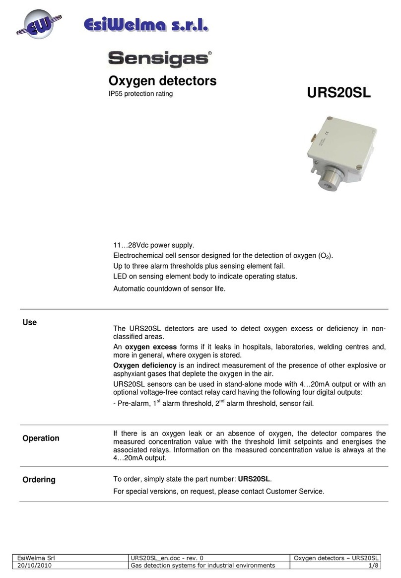
EsiWelma Sensigas URS20SL User manual
EsiWelma
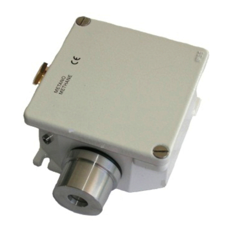
EsiWelma Sensigas URS40SL User manual
EsiWelma
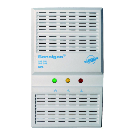
EsiWelma Sensigas ESN.0.P Series User manual
