EsiWelma Sensigas ESN.0.P Series User manual
EsiWelma s.r.l.
rev. 01 of 01-09-10 / pg.
1
E190.302
LPG and Methane gas detectors
for homes, recreational vehicles and similar sites
ESN.0.P.. ESN.0.G..
for LPG for Methane
Conformity standard EN50194
___________________________________________________________________________________________
LPG and Methane gas detectors for homes, recreational vehicles and similar sites.
Replaceable pre-calibrated sensor module prolongs the detector's life to 10 years or more.
230Vac, 12Vac/dc or 12…24Vac/dc power supply, depending on the model.
Solid state 12Vdc command output of max 13W suitable for ES.E.. Sensigas
®
solenoid valve (normally
open) or of another manufacturer but having the same characteristics.
Integrity control of electric connection between detector and solenoid valve.
Relay command output with voltage free contact suitable for 230Vac solenoid valve or other command
or alarm devices.
Possibility of parallel connection of more than one detector, also for monitoring different gases.
___________________________________________________________________________________________
Use
The ESN.0.P/.G detectors can be used to provide a visual/audible alarm and to control a gas
shut-off valve (and/or to control other alarm transmitters or actuating devices), where there are
abnormal concentrations well below the LPG or Methane gas hazard threshold.
___________________________________________________________________________________________
Operation
The detector will enter a warm-up phase after power-up; this will take about 60" and during
this time the detector is inoperative. At the end of the warm-up phase, the detector enters
normal operation mode, and will continue in this state until it detects gas.
Gas detection
When the gas concentration exceeds the threshold set-points, the detector senses its
presence and goes into the alarm condition indicated by the red LED coming on, by the sound
of the integrated buzzer and by the activation of the relay. After about 20s, it transmits a
command to shut off the manual reset solenoid valve (transmitting a command pulse of 0.5s
every 10s), signalled by a short series of flashes of the yellow LED.
Once the alarm condition is normalised, the detector is restored to its normal operating status.
Depending on the type of system constructed, it may be necessary to manually reset the
solenoid valve to restore gas flow.
___________________________________________________________________________________________
Power supply
Detector
230Vac 12Vac/dc 12…24Vac/dc
For LPG gas (type A) ESN.0.P.A ESN.0.P.A.D ESN.0.P.A.E
For Methane gas (type A) ESN.0.G.A ESN.0.G.A.D ESN.0.G.A.E
For LPG gas (type B) ESN.0.P.B ESN.0.P.B.D ESN.0.P.B.E
For Methane gas (type B) ESN.0.G.B ESN.0.G.B.D ESN.0.G.B.E
Type A = with direct command output for low voltage solenoid valve and auxiliary relay 10A / 250Vac
Type B= only visual/audible alarm (no command output)
___________________________________________________________________________________________
Available
models
and ordering
information
EsiWelma s.r.l.
rev. 01 of 01-09-10 / pg.
2
___________________________________________________________________________________________
Outputs
Detector status
LED
GREEN
LED
YELLOW
LED
RED
BUZZER RELAY SOLENOID
VALVE
Off OFF OFF OFF OFF OFF OFF
Sensor warm-up (60s) ON ON OFF OFF OFF OFF
Normal operation ON OFF OFF OFF OFF OFF
Sensor fail ON ON OFF OFF OFF OFF
Solenoid valve disconnected ON A OFF OFF OFF OFF
Gas alarm ON OFF ON ON ON PULSE
Operational test like in alarm, for the time the test jumper is kept short circuited
Key: ON = steady on / activated / switched OFF = off / deactivated / not switched
PULSE = 0.5s every 10s A= Rapid, continuous flashing
___________________________________________________________________________________________
Ensure compliance with standards in force for electrical wiring. The devices must be connected to the mains
and remain permanently powered. Omnipolar disconnection must be included in the mains.
Carefully read the instructions and electrical wiring diagrams in this document and follow them to the letter.
Keep this document in a safe place for future consultation.
The device must be installed by qualified technicians.
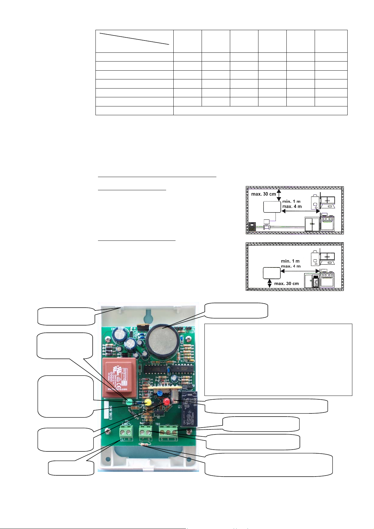
Installation
The detector must be installed:
Methane Gas: since this gas is lighter than air, it will be con-
centrated close to the ceiling. Install it about two metres from
the gas device and about 30 cm from the ceiling.
For LPG (liquid gas in cylinders): since this gas is heavier
than air, it will be concentrated close to the floor. Install it about
two metres from the gas device and about 30 cm from the floor.
The detector must not be installed:
• outdoors
• near stoves and cooking appliances
• near sinks and taps
• near exhaust hoods, windows, fans etc.
• in areas where dirt and/or dust can clog the front grille of
the detector
• where the temperature or humidity exceeds the detector's
operating limits
• in closed spaces (behind curtains, inside cupboards etc.).
___________________________________________________________________________________________
Operational
table
Installation and
Commissioning
Power supply
12Vdc solenoid valve command
10A / 250Vac relay output
Green LED
Power supply
Yellow LED
Sensor Fail
or warm-up
or S/V command
Red LED
A
larm
Replaceable & pre-calibrated Sensor Module
Cover clip-on point
Blocking the front cover:
After the wiring is completed and the operational checks
have been made,
tilt the front cover slightly upwards to fasten it onto the two
clip-on points shown in the figure.
Rotate the cover downwards, making sure that all three
LEDs are centred.
Press down firmly on the top of the cover until you
hear it click into place.
Make sure it is tight.
Piezoelectric buzzer
Load resistance: Only remove this if a 12Vdc
solenoid valve is connected
ESN.0.G
ESN.0.P

EsiWelma s.r.l.
rev. 01 of 01-09-10 / pg.
3
___________________________________________________________________________________________
Commissioning
Power up the detector and check that all the warm-up and normal operation phases are executed.
Carry out an operational response test by short-circuiting the test jumper located inside (or use a dedicated LPG
calibration canister with dosing valve and release a small amount of gas near the grille at the bottom) to check
the correct engagement of the solenoid valve and other command and/or alarm device connected to the relay; it
is advisable to repeat the operational test at least once a year, or after a prolonged period of stoppage. If other
test methods are used instead of the one described the detector may generate different, unexpected responses.
In particular, the use of inappropriate substances or vapours (alcohol or silicon-based solvents etc.) or in any
case, high concentrations of test gases could cause permanent damage to the sensing element and may cause
the detector to operate incorrectly.
The detector needs no periodic maintenance, with the exception of the periodic operational test and replace-
ment of the sensor module after 5 years. It is possible to replace the sensor module once only: 10 years
(or more) after the date it was first installed, the whole detector needs to be replaced.
Use a permanent marker to write the replacement date of the sensor module or detector on the plate
provided and place it in a visible position (after installation is completed).
Refer to the technical datasheet provided with the replaceable sensor module for replacement instruc-
tions.
Use a wet cloth and mild detergent to periodically clean the device.
Do not use aggressive detergents like alcohol, ammonia, solvents etc.
Before cleaning the detector, switch off the system power supply to avoid the risk of electric shock.
Warning The detector and its sensing element have been designed for ongoing use in areas where there is permanent
occupation by people, so normally pollution-free.
The presence of gases or vapours from some substances such as alcohol, silicon or solvents found in some
detergents or polishes, or from the fumes generated by cooking may cause inappropriate action of the detector
and in the long term could affect the reliability of the device. The particular Methane and LPG odorization made
by the distributor, together with the high sensitivity of the human olfactory apparatus, make it possible to smell
the presence of these gases already at extremely low concentrations, so a lot earlier than the detector. For
operational and regulatory reasons, the detector is calibrated to take action at a higher threshold which is still
very far below the hazard threshold.
___________________________________________________________________________________________
If an alarm goes off, stay calm, put out flames, switch off the gas or LPG cylinder at the meter, do not switch on
or off lights or any electrical appliances or equipment, open doors and windows to increase the flow of fresh air.
If the alarm stops, it is necessary to find out what set it off and take consequent action.
If the alarm continues and the reason for the presence of gas cannot be determined or eliminated, leave the
building and contact emergency services.
___________________________________________________________________________________________
(1) LEL = Lower Explosive Limit
___________________________________________________________________________________________
In the event
of alarm
Technical
specifications
Power supply (see available models) 230Vac
±
10% or 12Vac/dc
±
10% or 12…24Vac/dc
Frequency 50/60Hz
Consumption 2 VA
Command outputs • Solenoid valve at maximum 12Vdc / 13W
• SPDT relay - capacity of the contact 250Vac 10A (2500VA)
Alarm threshold 9% of L.E.L
(1)
of the Methane or LPG, depending on the model
Operational lifetime of a detector 5 years from installation,
extendable to 10 years with replacement of the sensor module
Max detectable area approx. 40 m
2
Visual warnings Green LED (power is on)
Yellow LED (warm-up / sensor abnormality - S/V cut off)
Red LED (gas alarm)
Audible alarms: Piezoelectric buzzer 85dB at 1m
Protection Rating IP42 when correctly installed
Product conformity standard
EMC Electromagnetic Compatibility
Low voltage (LVD)
EN50194
EMC 2004/108/EC – EN50270
LV 2006/95/EC – EN60335-1
Operating ambient temperature / humidity -10...+40 °C / 30... 90% RH (non condensing)
Dimensions Maximum dimensions: 142 x 85 x 54 mm
Enclosure ABS/PC UL94-V0 flame retardant

EsiWelma s.r.l.
rev. 01 of 01-09-10 / pg.
4
___________________________________________________________________________________________
Wiring diagrams:
Example a): - Command of a solenoid valve (Normally Open); in this mode, when the alarm threshold is ex-
ceeded, the solenoid valve will close and therefore the gas supply will be cut-off.
Example b): - Command of a solenoid valve (Normally Closed); in this mode the solenoid valve will close and
therefore the gas supply will be cut-off when: the alarm threshold is exceeded, if there is a
power failure and if the actual solenoid valve is disconnected.
Example c): - Command of a solenoid valve (Normally Closed) and of visual and audible alarms from several
locations. The contacts must be connected in series.
Example d): - Command of a solenoid valve (Normally Open) from several locations.
The outputs (up to 9) must be connected in parallel, respecting the polarities.
___________________________________________________________________________________________
___________________________________________________________________________________________
Connection
diagrams
Installation
data
To be filled in by Installer Installer's stamp
Installation site
Product order number
Part number
Installation date
230Vac or 12Vac/dc or 12…24Vac/dc
L+
N -
a)
ESN.0.G./.P.
4
3 5
7 6
NO
230Vac or 12Vac/dc or 12…24Vac/dc
L+
N -
b)
ESN.0.G./.P.
4
NC
7 6 3 5
230Vac or 12Vac/dc or 12…24Vac/dc
L+
N -
c)
ESN.F.0./.P.
4
NC
L+
N -
ESN.0.G./.P.
4
3 5 3 5
7 6 7 6
Max 9 detectors in parallel
230Vac or 12Vac/dc or 12…24Vac/dc
L+
N -
d)
ESN.0.G./.P.
4L+
N -
ESN.0.G./.P.
4
3 5 3 5
7 6 7 6
NO
This manual suits for next models
2
Other EsiWelma Gas Detector manuals

EsiWelma
EsiWelma Sensigas ESN.I.O Series User manual

EsiWelma
EsiWelma Sensigas UR 13/A Series User manual

EsiWelma
EsiWelma Sensigas URD20SE User manual

EsiWelma
EsiWelma Sensigas URD20SW User manual

EsiWelma
EsiWelma Sensigas URS40SI User manual

EsiWelma
EsiWelma Sensigas ESN I Series User manual

EsiWelma
EsiWelma Sensigas URS20SL User manual

EsiWelma
EsiWelma Sensigas URS40SL User manual

EsiWelma
EsiWelma Sensigas URD20SS User manual

EsiWelma
EsiWelma Sensigas URD20SL User manual


