Seada G88 HDMI User manual

G88 HDMI User Guide
This user guide provides basic instructions for setting up SEADA G88 HDMI video wall controllers using
its management software.
Document No. SD-EN-015
Document Version: 01

G88 HDMI User Guide
Table of Contents
1. Product Introduction.......................................................................................................................3
1.1. Product profile........................................................................................................................3
1.2. Product capability...................................................................................................................3
1.3. Specification & Parameters....................................................................................................4
2. Hardware Overview ........................................................................................................................5
2.1. Front Panel .............................................................................................................................5
2.2. Rear Panel...............................................................................................................................6
3. Connection Set up...........................................................................................................................7
3.1. RS232 connection...................................................................................................................7
3.2. Ethernet Connection ..............................................................................................................7
4. G88H Software User Guide.............................................................................................................7
4.1. Matrix Switch .........................................................................................................................9
4.2. Advanced Switch ..................................................................................................................10
4.3. Signal setting ........................................................................................................................12
4.4. PQ & Position........................................................................................................................12
4.5. Video Wall ............................................................................................................................13
4.6. Network Setting ...................................................................................................................15
5. Remote Control.............................................................................................................................15
6. Troubleshooting............................................................................................................................16
6.1. No Connection......................................................................................................................16
6.2. No Output.............................................................................................................................16
6.3. Black screen..........................................................................................................................16
7. G88H ASCII Command Lines..........................................................................................................17
7.1. Save Video Wall Preset Layout ............................................................................................17
7.2. Load Video Wall Preset Layout............................................................................................17
7.3. Read Device IP Address........................................................................................................17

G88 HDMI User Guide
1. Product Introduction
1.1. Product profile
The G88 HDMI version of video wall controller accepts up to 8 HDMI inputs and displays them on 8
different displays, each with a resolution up to 4K@60fps 4:4:4. G88 not only allows the user to display
a single input across all 8 screens, but also to display different input videos onto different screens
working like a matrix switcher. It can be easily controlled via Network, RS232, remote control or front
panel buttons. It supports both digital and analog audio at both input and output side.
1.2. Product capability
⚫8 HDMI 2.0 inputs with embedded audio
⚫8 HDMI 2.0 outputs with embedded audio
⚫Each input and output support resolutions up to 4K@60Hz 4:4:4
⚫8 analog audio inputs
⚫8 analog audio outputs
⚫Independent 8x8 IR Matrix
⚫Support audio embedded and de-embedded
⚫Support video wall function
⚫Support seamless matrix switching function
⚫Support EDID management
⚫Custom pre-set layouts for both Matrix and Video Wall Modes
⚫HDCP compliant
⚫Adjust Display settings such as Contrast and Saturation remotely
⚫Controllable via IP/serial port
⚫Controllable via front panel buttons
⚫Controllable via remote control

G88 HDMI User Guide
1.3. Specification & Parameters
Interface
HDMI-A
HDMI Version
HDMI2.0, HDCP2.2
Bandwidth
18Gbps
Input
800x600@60Hz,1024x768@60Hz, 1280x768@60Hz,
1280x800@60Hz,1280x1024@60Hz,1360x768@60Hz,
1366x768@60Hz,1400x1050@60Hz,1440x900@60Hz,
1600x1200@60Hz,1680x1050@60Hz,
1920x1200@60Hz,480p,576p,720p,1920x1080i,
1920x1080p,3840x2160@24Hz/25Hz/30Hz/50Hz/60Hz,
4096x2160@24Hz/25Hz/30Hz/50Hz/60Hz.
Output
3840x2160@60Hz, 3840x2160@50Hz,
3840x2160@30Hz, 3840x2160@25Hz,
1920x1200@60Hz,1920x1080@60Hz,
1920x1080@50Hz,1600x1200@60Hz,
1400x1050@60Hz,1366x768@60Hz,
1360x768@60Hz, 1280x1024@60Hz,
1280x768@60Hz, 1280x720@60Hz,
1280x720@50Hz, 1024x768@60Hz
HDMI Amplitude
T.M.D.S +/- 0.4Vpp
Differential impedance
100±15ohm
RS232/Ethernet control
Baud rate and protocol
Baud rate:9600, data bit:8,
stop bit:1, no parity checking
Ethernet
IE10.0+, HTML5
Power
Max Consumption
100W, 110-240VAC
Matrix Mechanical dimensions
Size(mm)
480(L)X300(W)X44.55 (H) including brackets
Weight
5Kg
Operating temperature
0 to 40°C
Storage temperature
-20 to 70°C
Permissible humidity
10%-50%

G88 HDMI User Guide
2. Hardware Overview
2.1. Front Panel
•OUTPUT/INPUT Buttons
Press buttons OUTPUT x+ INPUT y+ ENTER in order, switch input xto output y
•Power Button
Press and hold button for 1 second to power up the unit from standby mode
Press and hold button for more than 5 seconds to power down the unit to standby mode
•Lock Button
Press button more than 2 seconds and less than 6 seconds, to lock or un-lock front buttons. When locked, the Lock LED will be on.
Press button LOCK more than 6 seconds enter the input output lock menu, then press INPUT or OUTPUT button to toggle the input or output lock status,
then press ENTER to confirm, Press CLEAR to exit.
•MENU Buttons
Press buttons ALL + INPUT x+ ENTER in order, to switch input xto all the outputs, users can use this combination to switch between different inputs to
the video wall
Press buttons SAVE + OUTPUT y + ENTER to save current matrix/video wall layout as layout y
Press buttons RECALL + OUTPUT y+ ENTER in order, to recall layout y
Press buttons RES + OUTPUT y+ NEXT + ENTER in order, to change output resolution on OUTPUT y
Resolution choices: 3840x2160@60, 3840x2160@50, 3840x2160@30, 3840x2160@25, 1920x1200@60,1920x1080@60, 1920x1080@50,
1600x1200@60, 1400x1050@60, 1366x768@60,1360x768@60,1280x1024@60, 1280x768@60,1280x720@60, 1280x720@50, 1024x768@60
Press buttons EDID + INPUT x+ NEXT + ENTER, change the EDID mode of port INPUT x
EDID option: Manual, 3840x2160@60, 3840x2160@30, 1920x1200@60,1920x1080@60, 1280x1024@60, 1280x720@60, 1024x768@60
Manual EDID is loaded using G88H software
Press Clear button to cancel the current command function
Note: all these functions are also available using G88H software.

G88 HDMI User Guide
2.2. Rear Panel
•LAN(10M/100M/1000M) and RS232-1 Port are for PC control
•RS232-2 and IR-EXT ports are reserved for future development
•IR IN and IR OUT
IR IN/OUT routing follows video matrix routing
•Audio Input
8 x 3.5mm jack connectors to input external analog LR audio, user can select this audio to replace the corresponding embedded HDMI audio
•Audio Output
8 x 3.5mm jack connectors to output LR audio. Analog audio output ‘n’will always output the same audio content as on HDMI OUTPUT ‘n’.
•HDMI Inputs
8 x HDMI 2.0 inputs with embeded audio
•HDMI Outputs
8 x HDMI 2.0 outputs with embeded audio
•Power Supply Socket
110 ~ 240 VAC

G88 HDMI User Guide
3. Connection Set up
3.1. RS232 connection
RS-232 control, baud rate 9600, DB9 connector
3.2. Ethernet Connection
Connect the G88 unit with the control PC using either CAT cable. Make sure the PC is in the same
group of static IP address as G88.
Left is the default IP setting of G88. Users can change the IP
address once connected.
4. G88H Software User Guide
Users can run the G88H.exe software directly without installation. Software is on the disk in the
package or you can download it from the SEADA website. Double click the G88H software to get the
Dialog box as below
Default password for Administrator:111111
Default password for User: 000000
Users can change the password here as well
1. Click drop-down list to select account: Administrator or User
2. Input current password, then click the ‘modify’ button to open the Modify password window

G88 HDMI User Guide
Type in new password, then click the ‘modify’
button to change to the new password
Once log in, the following user interface will be shown on screen. The system will remember the last
connection setup and automatically try to connect the G88 system. If not, please check 4.1.1 and 4.1.2
for how to connect the unit with control PC.
There are 6main tabs in this software to help users set up and control the G88-HDMI video wall
controller.

G88 HDMI User Guide
4.1. Matrix Switch
Users can connect the G88 device to control PC and set up the device as matrix switcher in this section.
4.1.1. Connect to the G88 via UART for RS232
Connect the G88 to the control PC with a serial cable (a RS232 to USB cable is included in the
package)
If the software was connected via UART (RS232) last
time, software will connect to the G88 automatically
vis RS232. If it was used at Network last time, a
‘Network Timeout’ error message will be shown on screen and users need to set up as below for RS232
connection in the software
•Choose ‘UART’ instead of ‘Network’
•Select the COM port from the Port dropdown menu
•Press ‘Disconnected’ button to connect
The software will check all the parts of the device. A ‘Read data succeeded’ dialog box will be shown
on screen when finished.
4.1.2. Connect to the G88 via Network
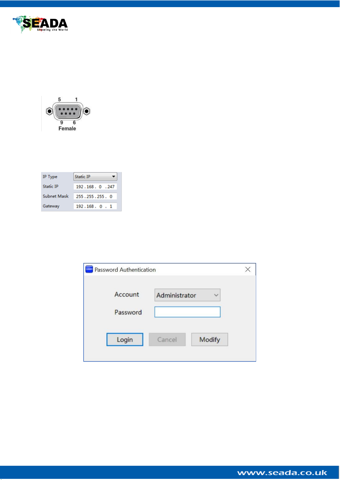
The default IP address for G88 controller is 192.168.0.247,Users need to change the IP address of
the control PC to the same network segment as the G88.
•Change the ‘Obtain an IP address automatically’ to ‘Use the following IP address’ to set up
a static IP address of TCP/IPv4 in Ethernet Properties
➢IP address: any address between 192.168.0.2 and 192.168.0.254 except the address which has
been taken by the G88
➢Subnet mask: 255.255.255.0, Default Gateway: 192.168.0.1
Connect the G88 with a CAT cable to the
control PC (cable included in the package)
If the software was connected via Network
last time, software will connect to the G88
automatically via network. If it was used at
serial port last time, a ‘Please select COM
port’ error message will be shown on screen and users need to set up as below for Network connection
in the software
•Choose ‘Network’ instead of ‘UART’
•Press ‘Search Device’ button to find the G88 on the network
•Highlight the device Press ‘Disconnected’ button to connect
4.1.3. Matrix Switch Routing
Users can switch and assign different inputs to the
selected outputs in the matrix. The name of the
input/output can also be changed by selecting the
default name –Input1/Output1 and replacing it
with the chosen name.
Users need to disable the video wall mode (Cancel
the splicing, see 4.5.2) to enable the matrix switcher mode.

G88 HDMI User Guide
4.1.4. Allset, Recall, Save As and Reset
•The Allset dropdown menu helps the users select a single input to be displayed on all the
screens
•Recall Mode: Recall a matrix switching preset layout. The device supports maximum 7 layouts.
•SaveAs Mode: Save up to 7 preset layouts for matrix switching
•Reset: Reset the unit to default factory configuration.
•EDID: Users can read the EDID from the output (from the receive device, such as screen) and
apply it to the input port
✓Read: read the EDID of the selected output
✓Save: save the displayed EDID after ‘Read’
✓Open: open an EDID from previous saved EDID
✓Write: write the current displayed EDID onto selected input
to customized input EDID
4.2. Advanced Switch
Users can set up the looping between different inputs on each output
The Advanced Switch tab will repeatedly send a batch of command lines at the interval time specified
in ‘Send cmd Periodically’
1. Select one or more outputs.
2. Select one or more inputs.

G88 HDMI User Guide
3. Use the arrow button (-->) to assign that input to the selected output or outputs.
4. When all required selections have been set up, click the Start button to run the commands.
The available options are:
•All outputs send combined –Include all outputs that have the content from the same input
as a single command.
•When others finished, start a next loop –Wait for all commands in the previous action having
been completed before sending the next batch of commands.
•Stop cmd after one loop –Only send the commands only once, no looping.
•Select all outputs –Selects all outputs when checked. Unselects all outputs when unchecked.
•Start –Begin the command cycles.
•Stop –Stop the command cycles.

G88 HDMI User Guide
4.3. Signal setting
In the
Signal Settings tab, users can use the ‘Read All’function button to recognize the type and resolution
automatically. Additionally, you can also manually read one Input/output at a time –pressing the
Read button next to the selected input will only read that input alone.
I. Input Type Shows the input video sources type (HDMI or DVI)
II. Input Format Shows the resolution of the input video sources
III. Audio Select
Auto: HDMI output embedded audio and analog audio output will get the audio from the
embedded audio of the HDMI input to be displayed on the output channel. If the input source is DVI,
the output system will get the audio from the input analog audio
External: HDMI output embedded audio and analog audio output will get the audio from the
corresponding analog audio of the HDMI input to be displayed on the output channel
IV. Output Type
• UHD-HDMI Set the respective output signal to HDMI without HDCP.
• UHD-DVI Set the respective output signal to DVI, with no audio output
• UHD-HDMI-1.4 Set the respective output signal to HDMI with HDCP 1.4 compliance.
• UHD-HDMI-2.2 Set the respective output signal to HDMI with HDCP 2.2 compliance.
V. Output Format
Users can manually change the output resolution here to match the requirement of the receiving
side (the default setting is 1920 x 1080@60, there are total 16 preset resolutions to choose from)
4.4. PQ & Position
This section allows the user to fine-tune the settings of each
output signal from the G88 software.
The dropdown menu at the top of the section allows the user to
select which screen to apply the settings to and Adjust the
Brightness, Contrast, Saturation and Sharpness sliders to the
selected output to adjust the image quality of that output.
The read option reads the settings of the monitor/screen that
are already in place and adjusts the values in the software,
while the reset button will reset the settings to their default
after they have been manually adjusted.

G88 HDMI User Guide
4.5. Video Wall
4.5.1. Video Wall Layout Setup
Users can set up the layout of the video wall in
‘VideoWall Setting’ by simply choosing how rows and
columns in the video wall. Total screens amount is up to 8
for G88 video wall controllers.
4.5.2. Creative the video wall
Left click to select the screen, then drag &
select the screens needed to form the video
wall.
Right-click, and choose ‘Screen splicing’to
form a video wall
Users can create more than one video wall
on G88. (e.g. they can create two 2x2 video
walls instead of one 2x4 video wall or 3, 4
independent video walls)

G88 HDMI User Guide
•Screen Splicing - This combines the selected screens into
one and displays the selected input across all the splicing
screens. For example, in the setup 2x4 at left, if all of them
are spliced, then the input selected by the user will be
displayed across all the 8 screens.
•Cancel Splicing –This will cancel the video wall and revert to
the matrix switching mode
•Screen –Cancel Splicing–This will cancel the very screen
and revert only that screen to the matrix switching mode to
form a Picture in Picture effect (See image left)
•Input Select –This allows the user to control which input is
displayed on video wall
•Output Select –The user can control which screen should
be mapped to which output (only available in matrix mode)
•Output Type –Allows the user to adjust the type of the
output (only available in matrix mode)
•Output Format –Controls the resolution of the output (only
available in matrix mode)
•Sync lock–to form sync between different screens in the
same video wall
4.5.3. Bezel Correction
Users can set up the bezel correction for the video walls here to compensate the frame of the
screens to make the whole video wall look like one large screen without any distortion. Users can
either use pixels of the screen frame width or millimeter of the screen display area to set up the
bezel correction here
4.5.4. Save and Load Pre-set Layout
The user can save the video wall preset layouts and load it later via
the Save Layout and Load Layout dropdown menu. Users can save
up to 7 preset layouts here.

G88 HDMI User Guide
4.6. Network Setting
Users can find all the device network information in this section and do the modification if needed.
Users can find the lost IP address using ‘Find via UART’ which only requires RS232 connection.
5. Remote Control
•Power Button
Press and hold button for 1 second to power up the unit from standby
mode
Press and hold button for more than 5 seconds to power down the unit
to standby mode
•Output/Input Buttons
Press buttons Output x+ Input yin order, switch input x to output y
•All Button
Press buttons All + Input xin order, to switch input x to all the outputs,
users can use this combination to switch between different inputs to the
video wall
•Save Button
Press buttons Save + Input yto save current layout as video wall layout y
•Recall Button
Press buttons Recall + Input yin order, to recall layout y
•Reset Button
•Press Reset + All buttons in order, to reset the unit to default factory
configuration

G88 HDMI User Guide
6. Troubleshooting
6.1. No Connection
6.1.1.Ensure the G88 is powered up
6.1.2.Ensure the PC and G88 at the same IP group
6.1.3.Ensure the IP address is correct for G88
6.1.4.IP address of each device will be shown on screen when no video input is applied.
6.2. No Output
6.2.1.Ensure the video source is on
6.2.2.Ensure the video source device sends the signal out (G88 INPUT statue LED light will be
on if input video signal presents)
6.3. Black screen
6.3.1.Ensure the G88 and screens are powered up
6.3.2.Ensure the connection to screens are OK
6.3.3.Ensure the screens on correct channel (DVI or HDMI)
6.3.4.Ensure that the inputs are assigned correctly (i.e. Input 1 on Output 1, Input 2 on
Output 2 etc.
6.3.5.Ensure that the output resolution is set up correctly. (i.e. if the output resolution is at 4k
and the screen only takes 1080p)

G88 HDMI User Guide
7. G88H ASCII Command Lines
Note:
•All spaces shown in the command are required.
•All commands in this section are always terminated with the ASCII carriage-return character,
0x0d. This is represented by the symbol in each command.
7.1. Save Video Wall Preset Layout
Operation
type (3 byte)
Spacer
(1 byte)
Target
(N bytes)
Spacer
(1
byte)
Command
type (10
bytes)
Spacer
(1 Byte)
Command
parameters
(1/2/3 bytes)
Command tail
(1 byte)
SET
Space
SYS
Space
TVWALL-
MODE
Space
x/xx/xxx
x is the layout
number
This is ASCII
carriage return 0x0d
For example, Save the current route to layout 1
Send: SET SYS TVWALL-MODE 1Receive: SYS TVWALL-MODE 1
7.2. Load Video Wall Preset Layout
Operation
type (3 byte)
Spacer
(1 byte)
Target
(N bytes)
Spacer
(1byte)
Command
type (10
bytes)
Spacer
(1byte)
Command
parameters
(1/2/3 bytes)
Command tail
(1 byte)
GET
Space
SYS
Space
TVWALL-
MODE
Space
x/xx/xxx
x is the layout
number
This is ASCII
carriage return 0x0d
For example, Load the preset layout 1
Send: GET SYS TVWALL-MODE 1Receive: SYS TVWALL-MODE 1
7.3. Read Device IP Address
Operation
type
(3 byte)
Spacer
(1
byte)
Target
(N
bytes)
Spacer
(1
byte)
Command
type
(10 bytes)
Command parameters
(N bytes)
Command tail
(1 byte)
SET/GET
Space
SYS
Space
IP
AT+WANN=mode,address,mask,gateway
This is ASCII
carriage return
0x0d
For example, GET the device IP (MAC: D8B04CB947DF )
Send: GET SYS IP Receive: SYS IP D8B04CB947DF DHCP,192.168.0.119,255.255.255.0,192.168.0.1
Send: GET SYS IP Receive: SYS IP D8B04CB947DF STATIC,192.168.0.222,255.255.255.0,192.168.0.24
Table of contents
Other Seada Controllers manuals

Seada
Seada SolarWall Pro Series User manual

Seada
Seada DS2 User manual

Seada
Seada G4K Pro User manual

Seada
Seada DS2 Instruction manual

Seada
Seada G24-HDMI Instruction manual

Seada
Seada G2000CTL User manual

Seada
Seada GM9 User manual

Seada
Seada GM9 Instruction manual

Seada
Seada G24 User manual

Seada
Seada G4K Instruction manual