Esma E782 User manual

1

2

Esma Inc.
PO Box 734 450 W. Taft Drive
South Holland, IL 60473
708-331-1855 800-276-2466 FAX 708-331-8919
Instructions for
Model E782
Betman Cleaning System
(Cleaner/Rinser/Rinser/Dryer)
Introduction
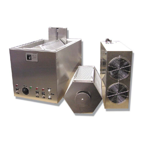
The Model E782 Cleaning system contains an ultrasonic cleaning tank,
two ultrasonic rinse tanks and a hot air drying chamber. Each
ultrasonic tank and the drying tank have separate control timers. The
ultrasonic tanks are supplied with heaters controlled with internal,
adjustable thermostats.
The ultrasonic cleaning tank 1 is adapted for a pump filter system.
Tanks 2 and 3 are both ultrasonic rinse tanks. Fresh rinse water can be
introduced into the system with the excess cascading to drain.
The E782 unit consists of two components: the main cleaning unit
containing the 316 Stainless Steel tanks housed in a 304 stainless
cabinet and a stainless power module cabinet containing the bulk of the
electronics.
Each tank has 6 potting transducers mounted on the bottom and is
equipped with a ball valve for draining.
The Power Module contains self-tuning modular circuit boards, high
velocity fans to cool the electronics, and an RFI filter to eliminate high
frequency noise feedback.
PLEASE READ THESE INSTRUCTIONS BEFORE INSTALLATION AND
OPERATION. If there are any questions, call (800) 276-2466.
INSTALLATION
Place unit on a bench close to a sink or drain. The power module can be
placed up to 8 feet away from tank, either on a shelf or in a cabinet.
The power module should not be positioned where it can be splashed
with liquids, where it can attract dirt or abrasives, or where the air
3

cooling by the fan can be restricted because of tight enclosures.
Clearance of 1” is necessary both at the air intake and exhaust.
PLUMBING
A number of valves and connectors have been supplied with unit. With
the PVC and plastic fittings and valves, add Teflon tape to the threads
and HAND tighten. (DON’T OVERTIGHTEN)
1. Three ball valves are supplied. Add Teflon tape and thread a ball
valve into the drain port of each tank. A ¼” NPT x ½” hose
connector is to be added to the outlet of each ball valve.
2. Tank 1 has input and output for a pump filter system.
3. Connect the water sources to the rinse inlet of tank 2 and 3.
A needle valve is supplied to regulate the water flow into the tank.
An internal solenoid starts or stops the flow in conjunction with
the timer. Connect your water supply to the ¼” compression input
of the needle valve.
4. Add ¼” NPT x ½” hose connector to the rinse outlet port of
tank 2 and 3 and connect a hose to drain. When operating, turn
timer 2 or3 ON and water comes in tank and cascades out to
drain.
5. Tanks 2 and 3 have high level sensors. If the water level becomes
too high in tank because of a blockage in the drain line, the sensor
will shut off this solenoid preventing any water overflow of tank.
Before starting, add water manually to tanks 2 and 3 so that the
ultrasonics do not run on an empty tank.
Pump Filter System
The cleaning tank 1 is equipped with electrical and plumbing outlets to
hook up the pump filter system. When the pump filter system is turned
ON the solution in tank 1 will recycle independent of timer. The
standpipe in the tank is the discharge to the pump. The tank level will
have to be higher than the standpipe or the standpipe can be removed
and the discharge will be at the bottom of the tank.
Initial Start Up Of Pump Filter
4

1. The initial start up works best if the pump filter system is on the
floor or lower than the tank.
2. Add liquid to the tank and allow liquid to flow into filter
chamber. Make sure ball valve on the pump filter is open.
3. Open the plug on top of filter chamber to bleed the trapped air in
chamber. Close this plug when liquid comes out.
4. If necessary, cycle pump on and off a few times to get trapped
air out of lines.
5. When maximum flow is achieved, use the ball valve on the
pump filter system to decrease the flow through tank. Excessive
flow through tank does decrease the ultrasonic action (Cavitation).
When all the air is removed from the system it may be more convenient
to place pump filter system on bench next to the cleaning tank. If the top
of the filter chamber is higher than the liquid level in tank, a filter
cartridge can be easily changed without draining any solution.
Electrical
The unit has two power cords that are plugged into the 120VAC,
50/60HZ source. The POWER MODULE is rated at 2550 watts, 120vac.
Two plug and cord assemblies from tank cabinet are plugged into power
module. A fuse, 25amp-125V, is located on the power module cabinet.
A separate power cord from tank cabinet is rated at 1550 watts, 120VAC
50/60HZ. The power cord supplies power to the tank heaters. A 15amp-
125V fuse is located on the front of the tank cabinet.
Operation
The MAIN switch on power module is left ON during daily operation.
Parts to be cleaned are placed in rack (basket) and rack is positioned into
the tanks. Never place parts directly on bottom tank (tank could
eventually be perforated). The basic principle of operation is the
enhancement and acceleration of the chemical cleaning by ultrasonic
action.
1. Heater – The tanks are supplied with 400 watts of heat controlled
by an adjustable, internal thermo switch. The thermo switch has
5

been adjusted to control the bath temperature at 160degrees F
when tank covers are on. If temperature needs to be changed,
there is a port at the rear of each tank module where a screwdriver
can be used to adjust the control knob of thermostat. The
thermostat is the same as used in the drying chamber mentioned
below. Use the same procedure for adjusting the temperature but
use caution that the bath temperature does not exceed 180
degrees F. CAUTION – Before adjusting thermostat turn power
OFF.
2. Timer – Turn timer knob clockwise to desired time, to start
ultrasonic action. When set time expires, the ultrasonic action is
terminated. Green indicator light is ON during operation.
3. Drying Chamber – The drying chamber uses forced hot air
thermostatically controlled at 160 degrees-180 degrees F. (set by
the manufacturer) Drying time will vary depending on the number
of parts to be dried, if hot or cold water was used to rinse parts
before drying and if the cover is on oven. Generally parts should be
dry in 10 minutes. CAUTION: Parts after drying will be hot (170
degrees F) and should be cooled before touching.
Tmer – Turn timer clockwise to desired drying time.
The air temperature of the dryer has been set at the factory to reach
170degrees F with cover on the oven. If you want to change the
temperature, there is a thermostat mounted above blower in closed
chamber behind oven. The temperature can be changed as follows:
1. Disconnect unit from 120V outlet.
2. There is a port at rear of dryer module where a screw driver
can be inserted to adjust the temperature.
3. Move control knob of thermostat slightly in clockwise
direction to increase temperature and counter-clockwise to
decrease temperature. Make only slight changes because a
30 degree angle change corresponds to an approximate 20
degrees F temperature change. Replace top plate on
chamber.
6

Maintenance
Periodically, the liquid in tanks must be changed:
-Unplug the unit from 120VAC outlet.
-Open ball valve at back of tank chamber to drain.
- Flush out tank with clean water and wipe dry.
-Close ball valve and add fresh solution.
Keep top of unit dry. Unit is manufactured from 304 stainless and can be
restored to the original finish with a stainless polish used for kitchen
appliances.
Modular Circuit Board
Unit E782 is equipped with three modular circuit boards that are easily
replaced if a problem occurs. Three small indicator lights on the power
module indicate that circuit boards are working. If the indicator light
goes out, a replacement circuit board can be shipped immediately. This
way the need for shipping the unit back for repairs is eliminated and the
disruption is minimal.
Warranty
The unit has a one year warranty, two year warranty on circuit boards
and lifetime warranty on tank weld seams and transducer bonds.
CALL 1-800-276-2466 FOR TECHNICAL SERVICE.
7
Table of contents
Other Esma Ultrasonic Jewelry Cleaner manuals
