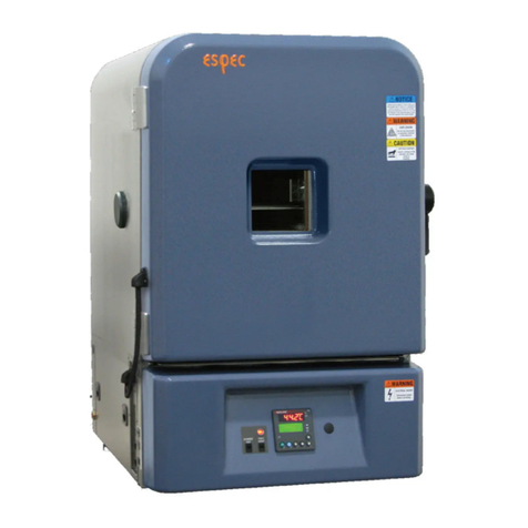
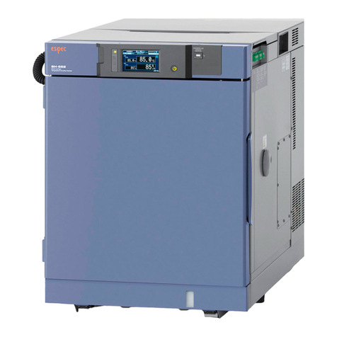
ESPEC EHS-211 User manual

User's Manual
Communication Function
RS-485
4013304025610
Applicable chambers : Highly Accelerated Stress Test
System(HAST Chamber)
EHS-211(M), 221(M), 411(M)
EHS-211MD, 221MD, 411MD
• Read this manual carefully before using the
equipment.
• Familiarize yourself with all safety
precautions before using the equipment.
• Keep this manual handy for future
reference.

はじめに
Liability
ESPEC CORP. assumes NO responsibility whatsoever for accidents or
equipment trouble arising from the failure to observe handling
instructions contained herein. Do not perform any operation or handle the
equipment in any way or form that is not described in this user's manual
or which is herein specifically prohibited. Careless usage of the sort may
result in unexpected damage to the equipment or accident.
• All rights reserved. It is strictly forbidden to reproduce any part of this manual without the express
written consent of ESPEC CORP.
• The contents of this manual are subject to change without notice.
• ESPEC CORP. will replace this manual if pages are missing or out of sequence.
© 2007 ESPEC CORP.

Introduction
This manual explains how to set up and use the RS-485 Communication
Function. It was written for users and engineers. Read it thoroughly to
ensure absolute safety and gain maximum performance from equipment.
Safety Indications
The following safety indications are used throughout this manual.
■Degree of DANGER
VERY
DANGEROUS
This mark means extremely
dangerous consequences may
arise, with the possibility of death
or serious injury to the user, if the
equipment is handled incorrectly.
DANGER
This mark means dangerous
consequences may arise, with the
possibility of death or serious
injury to the user, if the equipment
is handled incorrectly.
CAUTION
This mark means dangerous
consequences may arise, with the
possibility of somewhat serious
injury to the user and/or damage
to equipment and facilities, if the
equipment is handled incorrectly.
Keywords
The following keywords are used in this manual.
Note : Provides information necessary for gaining full performance
from the chamber or to prevent damage to equipment.
Procedure : Explains how to operate the chamber on a step-by-step
basis.
Reference : Offers supplementary information.
1

Contents
Introduction
Chapter 1 Overview
1.1 Communication Function ..............................................................6
・RS-485 ........................................................................................6
1.2 Communication Interface ..............................................................7
・RS-485 ........................................................................................7
1.3 Transmitted Data ..........................................................................8
・Types of Data ..............................................................................8
・Data Format ................................................................................9
・Error Messages .........................................................................10
1.4 Data Transfer ..............................................................................11
Chapter 2 Communication Setup
2.1 Communication Setup..................................................................16
・How to Change Communication Settings ...................................16
Chapter 3 Commands
3.1 Command List .............................................................................20
3.2 Monitor Commands ....................................................................22
・To Monitor Chamber Conditions.................................................22
・To Monitor Chamber Model and ROM Version...........................22
・To Monitor Humidifying Water Target and Monitored
Temperatures ...........................................................................23
・To Monitor Current Chamber Process........................................23
・To Monitor Door Lock Status......................................................24
・To Monitor Time Signal Output...................................................24
・To Monitor Operating Mode Setting............................................25
・To Monitor Control Mode Setting................................................25
・To Monitor Constant Mode Pattern No.......................................26
・To Monitor Constant Mode Parameters......................................26
・To Monitor Constant Mode Time Information..............................26
・To Monitor Program Mode Pattern No........................................27
・To Monitor Program Mode Current Step No...............................27
・To Monitor Program Mode Setup................................................27
・To Monitor Program Mode Pattern Total Time............................28
・To Monitor Program Mode Total Time Information.....................28
・To Monitor Auto Start Timer Information.....................................29
・To Monitor 0.1 Hour Timer Time.................................................29
2

3
・To Monitor Alarm Log.................................................................30
・To Monitor Power ON/OFF Status and Key Lock Status............31
・To Monitor Key Lock Status........................................................31
・To Monitor Communication Error Log.........................................32
・To Monitor Chamber Pressure (Only when equipped with
optional temperature, humidity and pressure recorder)............32
3.3 Setting Commands .....................................................................33
・To Switch to the Constant Mode.................................................33
・To Switch to the Program Mode .................................................33
・To Set the Control Mode.............................................................34
・To Set Constant Mode Pattern No..............................................34
・To Set Constant Mode Parameters ............................................34
・To Set Constant Mode Time.......................................................35
・To Set Program Mode Pattern No. .............................................35
・To Set Program Mode Step No...................................................35
・To Set Up Program Mode Patterns.............................................36
・To Set the Auto Start Timer........................................................37
・To Start Operations ....................................................................37
・To End Operations at Cycle End ................................................38
・To End Operations Immediately .................................................38
・To Lock/Unlock Keys..................................................................39
・To Clear the Communication Error Log ......................................39
Chapter 4 Example Applications
4.1 To Monitor Chamber Control Status from Computer ..................42
4.2 To Edit Test Setup from Computer .............................................43
Chapter 5 Specifications
5.1 Specifications ..............................................................................46
About RS-485 Communications ...................................................46
・RS-485 signal assignment..........................................................46
・About RS-485 Specifications......................................................46
・Documents configuration............................................................47

4

Chapter 1
Overview
5

Chapter 1 Overview
1.1 Communication Function
The communication function connects a chamber to a computer or some other
external device via a communication interface. This interface makes it possible
to control the chamber as well as monitor chamber control status and the
program being run with commands sent from the computer.
Reference Difference between "Computer Program" and "Test Program"
A "computer program" is a program created on computer. It is different from
the test program run in the chamber’s program mode.
The communication function comes standard with an RS-485 interface.
RS-485
RS-485 is a serial interface standard for multipoint communication lines,
adopted by the EIA (Electronic Industries Association). Whereas RS-232C
requires a 1-to-1 connection, RS-485 enables n-to-n connections. However,
with this system, the connection is 1-to-n.
6

Chapter 1 Overview
1.2 Communication Interface
RS-485
The RS-485 interface uses a DB-9 connector.
7

Chapter 1 Overview
1.3 Transmitted Data
Types of Data
Data is handled as either command data or response data.
■Command Data
Data sent from the computer to the chamber is treated as a command.
Commands are of the following two basic types.
• Monitor Commands
These commands are used to monitor the chamber's operating status and
conditions inside the chamber.
• Setting commands
These commands are used to change the chamber’s operating mode or
conditions inside the chamber such as target temperature/humidity.
■Response Data
Data returned from the chamber in response to computer commands is treated
as a response. Responses are of the following two basic types.
• Reception Status
This response tells the computer whether the setting command it sent was
processed correctly or not.
<When the setting command is correctly processed>
"OK : address, setting command"
<When the setting command is not correctly processed>
"NA : error message"
(For details on error messages, see Table 1.1.)
• Monitor Data
This data is sent in response to monitor commands from the computer.
<When the monitor command is correctly processed>
"monitored data"
(For details on responses, see "3.2 Monitor Commands".)
<When the monitor command is not correctly processed>
"NA : error message"
(For details on error messages, see Table 1.1.)
8

Chapter 1 Overview
Data Format
■Command Data Format
Command data sent from the computer has the following format.
address, main command [, optional parameter] delimiter
Address
Reference This communication function recognizes address 1 to 16. Single digit
address can be preceded with a "0" as in "01, 02, 03 … " or the "0" can be
left out. A comma (,) must separate the address and main command.
■Response Data Format
The response data returned from the chamber to the computer has the
following format.
reception status data or monitored data delimiter
Reference About Main Commands and Optional Parameters
• Main commands and optional parameters are expressed as ASCII text in
either capital or small case letters.
• Spaces between characters are automatically deleted.
• Temperature and control output data are valid to one place below the
decimal. All other numerical data is recognized as a whole number.
9

Chapter 1 Overview
Error Messages
When command data sent from the computer is not correctly processed by the
chamber, the chamber returns an "NA :" code attached with an error message.
These messages and their meaning are given here below.
Table 1.1 Error messages
Error message Meaning Example
CMD ERR Chamber could not recognize
the command data. • If "MOD?" is sent as the command.
The correct command is "MODE?"
ADDR ERR Invalid address expression • If an unacceptable data format is
specified as the address
CONT NOT READY-1 The chamber could not execute
the command. • If a command is sent while making
settings from the operating panel
CONT NOT READY-2 The chamber could not execute
the command. • If a command is sent while control
power is OFF
CONT NOT READY-3 The chamber could not execute
the command.
• If a command is sent when the
chamber is not in the STANDBY
process
CONT NOT READY-4 The chamber could not execute
the command. • If a command is sent when
operations are not ready to start
CONT NOT READY-5 The chamber could not execute
the command. • If an inapplicable command is sent
during operation
CONT NOT READY-6 The chamber could not execute
the command.
• If a constant mode command is
sent when the chamber is not in the
constant mode
CONT NOT READY-7 The chamber could not execute
the command.
• If a program mode command is sent
when the chamber is not in the
program mode
CONT NOT READY-8 The chamber could not execute
the command.
• If an overflow error occurs
CONT NOT READY-9 The chamber could not execute
the command.
• If a time-out occurs while
calculating the program mode
pattern total time
PARA ERR Parameter error
• The parameter is missing in the
command.
• If the attached parameter cannot be
recognized because it is wrongly
written, etc.
DATA OUT OF RANGE Data is out of the specified
range. • If an option parameter is input out of
the setting range
10

Chapter 1 Overview
1.4 Data Transfer
CAUTION
• Wait to receive the response of a previous command
before sending the next command.
If a subsequent command is sent without waiting for the
response of a previous command, communications may not be
successful.
• When sending commands to the same address,
provide a time lag from when reception of the first
command completes to when the next command is
sent.
If commands are sent continuously, the communication load
may destabilize control.
1. Send to address 1.
Procedure
2. Receive response from address 1.
3. Wait a discrete amount of time as demanded by the type of command
sent in procedure 1. (See * below.)
4. Send to address 1.
* The time lag should be as follows.
For monitor commands
0.02 seconds or less
However, the program mode pattern total time monitor command (PCHK?)
must be processed within 0.1 sec.
11

Chapter 1 Overview
■Standard Mode
The computer sends commands (setting command or monitor command) to the
chamber and the chamber returns a response (reception status or monitor
data) to the computer.
Chamber
Computer
Setting command
When a processable setting
command is received
"OK : setting command"
Monitor command
When a processable monitor
command is received
"response"
12

Chapter 1 Overview
■E-BUS Mode
When the E-BUS mode is selected as the data transfer mode, you have the
choice of using echo back or not.
• When Echo Back is ON
When echo back is ON, the chamber returns responses to the computer in
the below format.
<Response to setting commands>
reception status data delimiter
<Response to monitor commands>
reception status data delimiter monitored data delimiter
Therefore, when the entire response data including the delimiter is treated as
a single data set, data transfer is as follows.
Computer Chamber
Setting command
When a processable setting
command is received
"OK : setting command"
Monitor command
When a processable monitor
command is received
"OK : monitor command"
"response"
13

Chapter 1 Overview
• When Echo Back is OFF
When echo back is OFF, the chamber does not return a response to
computer commands until it receives the data transfer trigger. With this
communication function, "address,G" is used as the data transfer trigger
instead of the command data. In this case, data transfer is as follows.
Computer Chamber
Setting command When a processable setting
command is received,
the setting is changed on the
chamber side, but a
response is not returned.
Monitor command
When a processable monitor
command is received
"address,G"
When the trigger is detected,
response data is returned.
"response"
14

Chapter 2
Communication Setup
You can set up communications from the communication setup mode.
15

Chapter 2 Communication Setup
2.1 Communication Setup
How to Change Communication Settings
1. Activate power, press and hold the 【◄】key on the operating panel
and press the 【OPERATION SET/ENTER】key to enable setting
changes.
The communication interface protocol appears in the temperature
display area, the setting item in the humidity display area and the
setting value in the time display area.
4 8 5 ←Connection interface protocol RS-485
←Setting item
←Setting value
2. Select a setting item with the 【◄】and 【NEXT】keys, and change
the setting value with the 【▲】 and 【▼】 keys. After making all
setting changes/checks, press the 【OPERATION SET/ENTER】key.
The setting value is saved in the nonvolatile memory and made active.
Press any other key to interrupt the setting operation and disengage
the setting change operation.
Information displayed while making settings and those meanings are
given below.
Humidity display area: Setting items
Adr : Address
dEL : Delimiter
PAr : Parity setting
StP : Stop bit
LEn : Data length
bPS : Baud rate
Eco : Echo ON/OFF
Ebs : E-BUS protocol
16

Chapter 2 Communication Setup
Time display area: Content of each setting item (5 setting items)
Address
1 to 16: 1 to 16
Delimiter
Cr : CR
LF : LF
CrLF : CRLF
Parity setting
no : None
EuEn : Even
Odd : Odd
Stop bit
1 : 1 bit
2 : 2 bit
Data length
7 : 7 bit
8 : 8 bit
Baud rate
48 : 4800 bps
96 : 9600 bps
192 : 19200 bps
Echo ON/OFF
OFF : OFF
On : ON
E-BUS protocol
OFF : OFF
On : ON
17

Chapter 2 Communication Setup
18
This manual suits for next models
8
Table of contents
Other ESPEC Laboratory Equipment manuals