ESPROS TOFcam-660 User manual

TOFcam-660
Installation and Operation Manual
General Description
The TOFcam-660 is a cost optimized 3D camera. It is based on the
ES ROS proprietary time-of-flight technology using the epc660
TOF flagship chip. The camera controls the illumination and the im-
ager chip to obtain distance and grayscale images. The depth im-
ages are compensated against ambient light, temperature and re-
flectivity of the scene. By using one of the offered ES ROS user
interfaces, 3D point clouds in a cartesian coordinate system are
available. Thanks to the high performance of the imager chip with
the unique ambient light suppression, the camera can be used un-
der full sunlight condition.
This document allows a TOFcam-660 user easily to get the camera
connected and started using a computer. It contains a description
of all features of the device as well as all functions of GUI and ROS
application. The complete description of interfaces, protocols and
commands allows to connect the module to integrated systems. A
software development kit (SDK) with all C++ source codes,
libraries and drivers including is available by ordering the ES ROS
epc660 evaluation kit.
Figure 1: TOFcam-660
Figure 2: Color coded TOF distance
Features
■320 x 240 pixels QVGA resolution (76'800 pixels)
■Measurement rate up to 20 TOF measurements per second
(1.5 MIO distance and amplitude values per second)
■Distance measurement and object recognition from centimeters
to 100 meters
■Four different field of view and operating ranges available
■Fully calibrated and compensated
■Sun- and ambient-light tolerant up to 100 kLux
■GigE and USB interface
■Various user interfaces: GUI, ROS, ython
□Evaluation of TOFcam-660 main features
□Store and recall camera configuration
□Easy collection of distance data and point clouds
□Many explanations about “time of flight done right”
Applications
■Research in various scientific fields
■IoT applications
■Evaluation and development of a epc660 based TOF sensor
□Automatic vehicle guidance, in-cabin monitoring
□Object classification and safeguarding
□Face recognition, Gesture control (man-machine-interface)
Figure 3: oint Cloud
Figure 4: Amplitude as logarithmic gray scale
© 2021 ES ROS hotonics Corporation
Characteristics subject to change without notice
1 / 35 Installation_and_Operation_Manual_TOFcam660_V.02
www.espros.com

Contents
1. Before you start ......................................................................................................................................................... 3
1.1. recaution and Safety ..........................................................................................................................................................................3
1.2. Updates.................................................................................................................................................................................................3
1.3. Important Notes.....................................................................................................................................................................................3
2. A reviations ............................................................................................................................................................ 4
3. Quick guide ................................................................................................................................................................ 6
3.1. Connecting the camera module ...........................................................................................................................................................6
3.2. Camera settings ...................................................................................................................................................................................6
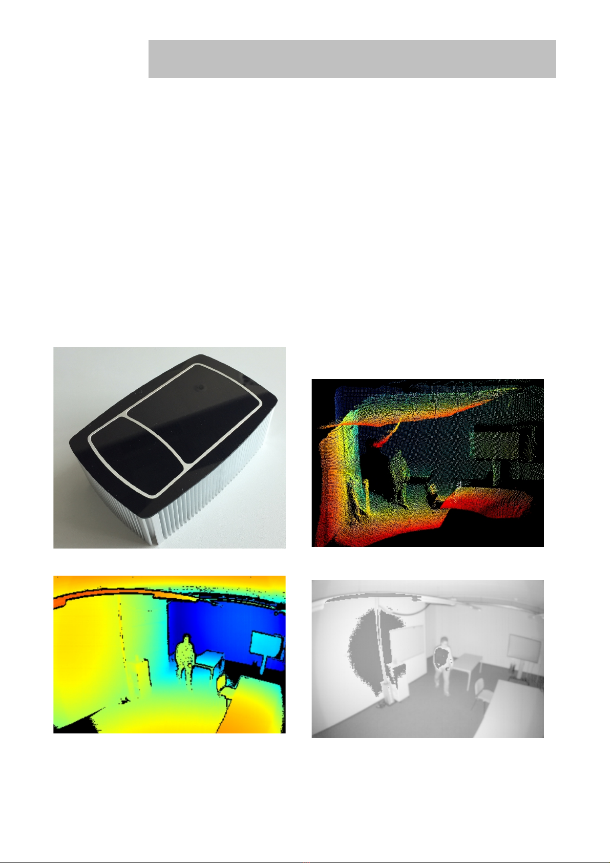
4. TOFcam-660 time of flight camera ........................................................................................................................... 7
4.1. System overview ..................................................................................................................................................................................7
4.2. Scope of delivery ..................................................................................................................................................................................7
4.3. Ordering information ............................................................................................................................................................................7
4.4. Technical data ......................................................................................................................................................................................9
4.5. Mechanical data .................................................................................................................................................................................10
4.5.1. Mechanical features ...........................................................................................................................................................................10
4.5.2. Mechanical dimensions ......................................................................................................................................................................11
4.6. Camera connectors.............................................................................................................................................................................11
4.6.1. LAN connector ...................................................................................................................................................................................11
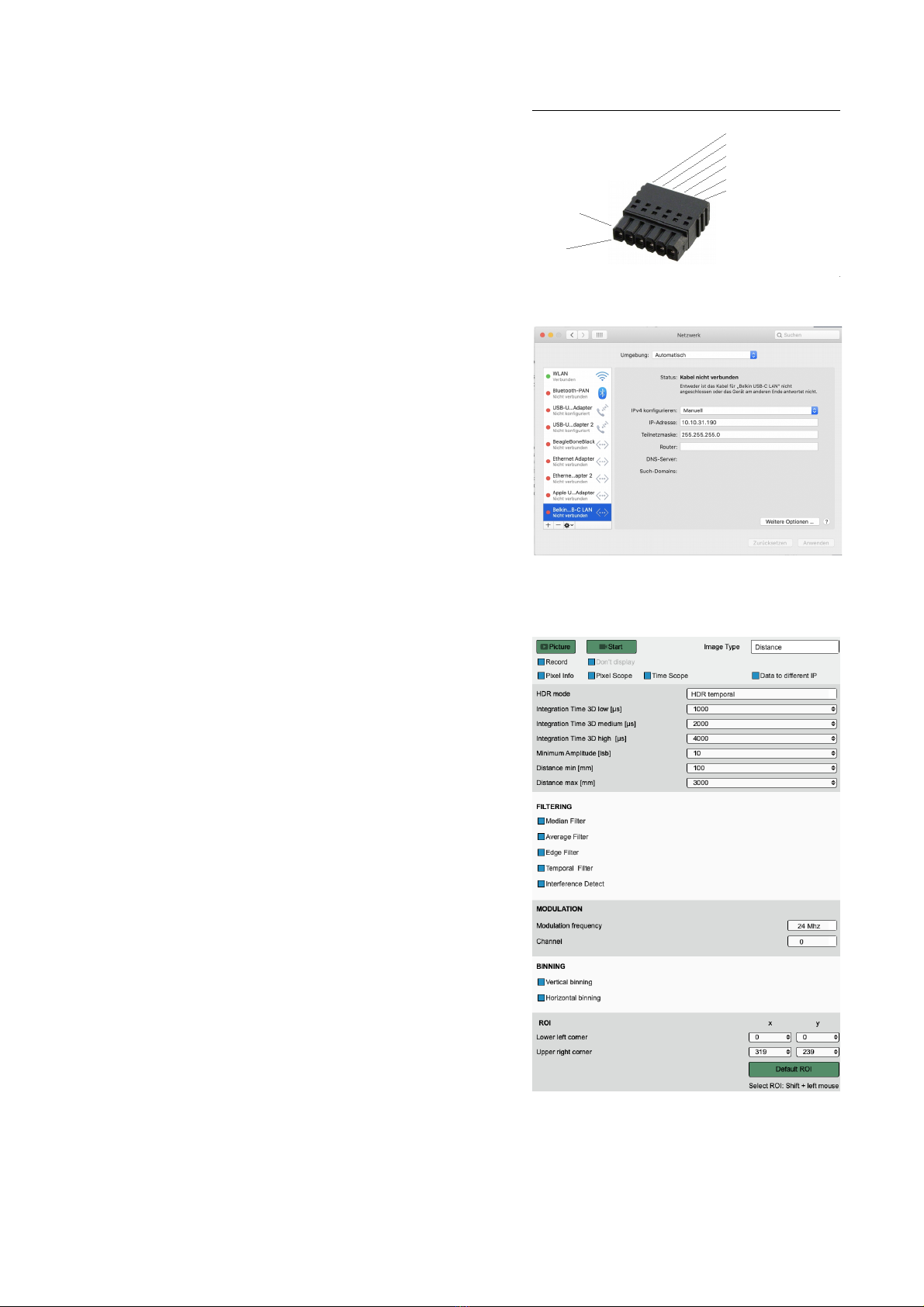
4.6.2. ower and G IO connector ...............................................................................................................................................................11
4.6.3. I reset button ....................................................................................................................................................................................12
4.7. Start up ...............................................................................................................................................................................................12
4.8. Firmware upgrade ..............................................................................................................................................................................13
5. GUI ............................................................................................................................................................................ 14
5.1. GUI main window ...............................................................................................................................................................................14
5.1.1. View menu .........................................................................................................................................................................................14
5.1.2. lay menu ..........................................................................................................................................................................................17
5.1.3. Live image window .............................................................................................................................................................................17
5.1.4. oint cloud .........................................................................................................................................................................................18
5.1.5. Decided information windows ............................................................................................................................................................19
5.2. Network settings .................................................................................................................................................................................20
5.3. Configurations menu ..........................................................................................................................................................................20
6. Operating the device with a ROS ...........................................................................................................................21
6.1. ROS camera driver.............................................................................................................................................................................21
6.1.1. What is ROS?.....................................................................................................................................................................................21
6.1.2. Building the ROS driver .....................................................................................................................................................................21
6.1.3. Running the ROS driver with launch file ............................................................................................................................................21
6.2. ROS A I..............................................................................................................................................................................................22
6.2.1. Start of the node..................................................................................................................................................................................22
6.2.2. ublished topics..................................................................................................................................................................................22
6.2.3. Dynamically reconfigurable parameters.............................................................................................................................................23
7. Communication interface ....................................................................................................................................... 24
7.1. Description .........................................................................................................................................................................................24
7.2. Command Connection (TC ) .............................................................................................................................................................24
8. Communication ....................................................................................................................................................... 25
8.1. Commands .........................................................................................................................................................................................25
8.2. Responses .........................................................................................................................................................................................27
8.3. Factory commands..............................................................................................................................................................................28
9. Measurement Data Connection (UDP).................................................................................................................... 30
9.1. acketizing (transport layer)...............................................................................................................................................................30
9.2. ayload (application layer)..................................................................................................................................................................31
9.3. ayload Header..................................................................................................................................................................................31
9.4. Data types and format of measurement data.....................................................................................................................................32
9.5. Measurement data..............................................................................................................................................................................32
10. Maintenance and disposal....................................................................................................................................... 33
10.1. Maintenance........................................................................................................................................................................................33
10.2. Disposal...............................................................................................................................................................................................33
11. Addendum................................................................................................................................................................. 34
11.1. Related documents.............................................................................................................................................................................34
11.2. Links....................................................................................................................................................................................................34
11.3. Licenses..............................................................................................................................................................................................34
12. IMPORTANT NOTICE............................................................................................................................................... 35
© 2021 ES ROS hotonics Corporation
Characteristics subject to change without notice
2 / 35 Installation_and_Operation_Manual_TOFcam660_V.02
www.espros.com

1. Before you start
1.1. Precaution and Safety
Eye safety: Do not look directly into the camera under operation. Depending on the mode of operation, the
camera device emits highly concentrated non-visi le infrared light. It can e hazardous to the human eye. The
use of these devices has to follow the safety precautions given in IEC62471.
The camera module is an electronic device. Handle it with the necessary ESD precaution.
Over-voltage: Use only a power supply which correspond to the data sheet of the camera to avoid damage of the device
or cause danger for humans.
Cable-tripping: lace or mount the camera on solid ground or fix it correctly on a solid support. lace cables carefully.
Falling devices can be damaged or harm persons.
The camera comes with its own calibrated TOFCOS. Do not alter the TOFCOS without obeying the instructions herein.
Be careful to the window surfaces of the camera. Never use any solvents, cleaners or mechanically abrasive towels or
high pressure water to clean the camera.
Operate the device in compliance with the local EMC regulations.
This camera is not a safety device. It may not be used in safety applications, explosive atmospheres or in radioactive
environment, except the user implements the required safety measures, e.g. by redundancy. However, the sole respon-
sibility for the safety of the application is by the user.
LIMITED WARRANTY - LOSS OF WARRANTY
This camera should only be installed and used by authorized persons. All instructions in this data sheet and in the
related documents shall be followed and fully complied with. In addition, the installer and user is required to comply with
all local laws and regulations. The installer and user is fully responsible for the safe use and operation of the system. It
is the sole responsibility of the installer and the user to ensure that this product is used according to all applicable codes
and standards, in order to ensure safe operation of the whole application. Any alteration to the devices by the buyer,
installer or user may result in device damage or unsafe operating conditions. ES ROS hotonics AG is not responsible
for any liability or warranty claim which results from such manipulation or disregarding of given operating instructions.
ES ROS hotonics AG is an ISO 9001: 2015 certified company.
This product is according to European Union standards and free of hazardous substances.
1.2. Updates
ESPROS Photonics is constantly striving to provide comprehensive and correct product information. Therefore, please check
ESPROS' we site regularly for updated versions of data sheets and documentations: www.espros.com
Download the latest Flyer of TOFcam-660.
Download the latest Installation and Operation Manual of the TOFcam-660.
Download and use the latest software package “TOFCAM660_SW_ ackage” containing a graphical user interface
(GUI) for Windows, Mac or Linux computers, a robot operating system (ROS) application, and a ython A I framework.
The current firmware “TOFCOS” is part of the GUI which allows an easy upgrade of the camera with current firmware.
If there are any questions, please contact your ES ROS sales office or send an email to [email protected].
Download and use the latest software development kit (SDK) “TOFCAM660_SDK” containing all source codes of the
firmware, GUI, ROS and A I. Unpacking the SDK is password protected. Get back to ES ROS to check whether you
fulfill the requirements to get the password.
1.3. Important Notes
Notes on PRELIMINARY versions:
THIS MANUAL IS UNDER CONSTRUCTION. IMPORTANT PARTS MAY BE MISSING
Colored marking in text means “under consideration” and refers to not yet applicable or verified information.
Values and/or information are either estimates or show the applicable principle only.
© 2021 ES ROS hotonics Corporation
Characteristics subject to change without notice
3 / 35 Installation_and_Operation_Manual_TOFcam660_V.02
www.espros.com

2. A reviations
Designator Description
3D Three dimensional
ACK Acknowledged
ADC Analog-to-digital converter
A I Application rogram Interface
Binning Summation of a defined number of pixels. Binning can be done in the charge (analog) or in the digital domain
CMD Command
C U Central rocessing Unit
CRC Cyclic redundancy check (checksum)
cwTOF Continuous wave modulated time of flight
DCS Differential correlation sample
DLL Delay locked loop, controllable delay line
DRNU Distance response non-uniformity: Distance error from pixel to pixel with a target at the same distance
EMC Electromagnetic compatibility
EMI Electromagnetic interference
ESD Electrostatic discharge
FoV Field of view
fps Frame rate, number of images per second
Frame One image
GigE Gigabit Ethernet
GND Ground terminal, negative supply voltage
G IO General urpose Input / Output
GS Grayscale
GUI Graphical User Interface
HDR High dynamic range
ID Identifier
IN Input terminal which is used to sense a high or low voltage
I Internet rotocol address
ISO International organization for standardization
JEDEC Joint electron device engineering council
LAN Local Area Network
LED Light emitting diode used to illuminate the scenery or as indicator
LSB Least significant bit
LVTTL Low voltage transistor transistor logic
MSB Most significant bit / byte
NACK Not acknowledged
NF Narrow field of view
OUT Output terminal which is can be set to high or low voltage
QVGA Quarter Video Graphics Array
RMS Root mean square
RoHS Restriction of hazardous substances
ROI Region of interest in the pixel-field
ROS Robot Operating System
RX Receive terminal, data in
SDK Software Development Kit
© 2021 ES ROS hotonics Corporation
Characteristics subject to change without notice
4 / 35 Installation_and_Operation_Manual_TOFcam660_V.02
www.espros.com

Designator Description
SF Standard field of view
SW Software
TBD / tbd To be defined, information not yet available or not valid
TOF Time of Flight
TOFCOS Time of Flight Camera Operating System
TTL Transistor transistor logic
TX Transmit terminal, data out
UART Universal asynchronous receiver transmitter
USB Universal Serial Bus
UWF Ultra wide field of view
VDD ositive supply voltage
WF Wide field of view
Table 1: List of abbreviations used in this document
© 2021 ES ROS hotonics Corporation
Characteristics subject to change without notice
5 / 35 Installation_and_Operation_Manual_TOFcam660_V.02
www.espros.com

3. Quick guide
3.1. Connecting the camera module
First of all you need to prepare a power supply for the camera. Therefore use
the 6 pin connector which is included in the scope of delivery. If you ordered the
power supply and power adapter cable as accessory according to chapter 4.3
then you don't need to provide a separate power supply connected to this 6 pin
connector.
You need to install the Graphical User Interface onto your computer. This is
available with the software package "TOFCAM660_SW_ ackage" from our
download page.
You need to consider the I address of the camera which is 10.10.31.180 with
sub-net mask 255.255.255.0. So you need to operate the camera within the
same network range. If your computer has a RJ45 LAN connector you can
connect the camera directly with corresponding network settings of the LAN-
adapter in your computer. You can choose a manual I 10.10.31.190 for your
computer e.g. If you use a RJ45 to USB adapter you need to configure the
settings of your USB adapter accordingly. You can choose a manual I address
10.10.31.190 for your USB adapter e.g. Disable the firewall on your computer or
add an exception for the camera application. The firewall might block the visual-
ization of data in the image window.
•Connect your camera with your computer using a RJ45 patch-cable.
•Connect your camera to the proper voltage using the prepared power
supply.
•Start the GUI on your Computer. The connection to the camera will
be indicated in the corner bottom left of the main window of the GUI
(Connected to 10.10.31.180 - in green letters). This can take around
60 seconds. If there is no connection for several minutes then please
disconnect and re-connect the power supply. If this don't help you
need to check the network settings of your network adapter as
described previously.
3.2. Camera settings
•Choose Image Type “Distance“
•Select HDR mode “HDR temporal“ with integration times:
“low“ = 1000µs / “medium“ = 2000µs / “high“ = 4000µs
Depending on distance and reflectivity of the objects in the scene
these values need to be reduced.
•For object detection set the "Minimum Amplitude" to 10 LSB, for
accurate measuring to 100 LSB (this are good starting points, fine-
tuning possible).
•Set the "Distance min" value to 100 mm and the “Distance max“ to the
effective maximum distance in your scenery.
•Disable all Filter functions.
•Depending on the maximum distance in your field of view you should
choose a suitable "Modulation frequency" (unambiguity). For long
distance a low modulation frequency is required.
•If you choose a modulation frequency which is not 12 MHz (24 MHz
e.g.) the camera is not calibrated. In this case it might be required to
consider a corresponding offset.
•Start streaming with the “Start” button.
•Decrease the "Integration time 3D low" to a value where you get no
ADC overflow (pink) or saturated pixels (purple). Adjust the integration
time “medium“ and “high“ accordingly.
•lay with filtering: enable "Temporal Filter" e.g.
•Optimize the color scale (visual graduation) of the relevant objects in
your scenery by changing the "Distance min" value.
•Change the image type to the illustration of the scenery you like to
see.
© 2021 ES ROS hotonics Corporation
Characteristics subject to change without notice
6 / 35 Installation_and_Operation_Manual_TOFcam660_V.02
www.espros.com
Figure 5: 6-pin power-supply and G IO connector
CONN_ hoenix_6 in_1778667
6G IO OUT1 (optional)
5G IO OUT0 (optional)
4G IO IN1 (optional)
3G IO IN0 (optional)
2 GND
1 + 24VDC, min. 2.5A
CHAMFERD
EDGED
Figure 6: I configuration of a USB-LAN adapter
Figure 7: GUI window for camera settings

4. TOFcam-660 time of flight camera
4.1. System overview
The TOFcam-660 is a general purpose camera based on the ES ROS epc660 cwTOF imager chip:
•24VDC power supply input
•RJ45 LAN connector
•General purpose I/O connector
•NX I.MX RT1062 microcontroller
•The micro controller board communicates with the epc660 chip carrier board through an ultrafast TCMI serial interface.
•One out of four different lenses depending on the camera model focus the reflected light from the scenery onto the pixel field of
the imager chip.
•NIR band pass filter, AR coatings and stray-light suppression for optimal optical performance
•LED illumination adopted to the specific field of view depending on the camera model
•TOF camera operating system (TOFCOS) for camera control, distance calculation and filtering
•Communication by Ethernet
•Application programming interface (A I) for further processing is available. It opens the world for point cloud computing, using
open source tools or creating own customer applications.
•ROS device drivers for Linux available
•Windows, Mac and Linux GUI available
4.2. Scope of delivery
Pieces Part Name Picture
1 Time of Flight Camera TOFcam-660 consisting of:
–Aluminum housing
–Receiver optic
–Illumination cpl.
–C U electronics
–interfaces
1 6 pin connector plug for 24V power supply and G IO
–lug with snap-fit clamps
–Connecting instructions
–in assignment
4 Self tapping screws for camera mount
1 Software package containing GUI, ROS, ython A I and current
Firmware. Available on the ES ROS download page.
1 Documentation
(useful additional information available on the Espros download page )
Table 2: Scope of delivery
4.3. Ordering information
Picture Part No. Name Description
100 654 TOFcam-660-NF FoV 31 x 24°, 81m operating range
50LSB on 18% reflective target at full sunlight
100 655 TOFcam-660-SF FoV 70 x 51°, 25m operating range
50LSB on 18% reflective target, up to 78kLux
100 656 TOFcam-660-WF FoV 108 x 77°, 11m operating range
50LSB on 18% reflective target at full sunlight
© 2021 ES ROS hotonics Corporation
Characteristics subject to change without notice
7 / 35 Installation_and_Operation_Manual_TOFcam660_V.02
www.espros.com

100 595 TOFcam-660-UWF FoV 125 x 93°, 6m operating range
50LSB on 18% reflective target
100 638 24VDC connector Included in TOFcam-660 basic unit.
To connect the camera to a corresponding power
supply.
100 609 ower adapter cable Cable to connect a TOFcam-660 directly with the
power supply 100 282
100 282 ower Supply 24VDC Input 100 … 240V
DC output: 24V, 2.5A
100 284 ower cord 2 pole CH/EU plug
300 189 ower cord adapter
CH/EU - US
300 780 atch cable, 2m, RJ45
300 781 Adapter RJ45 to USB GigE
300 473 Cable USB A to Micro
USB
Table 3: Order information for cameras and accessories
© 2021 ES ROS hotonics Corporation
Characteristics subject to change without notice
8 / 35 Installation_and_Operation_Manual_TOFcam660_V.02
www.espros.com

4.4. Technical data
All characteristics are at typical operational temperature TA = +25ºC
Parameter Description Conditions Min. Typical Max. Units Comments
VDD Main supply voltage Ripple 1 < 50 mVpp _ 24 _ VDC
IDD Supply current _ _ _ A
λ Operating wavelength 940 nm
RESIMAGE Image resolution 320 x 240 ixel QVGA
FoV Field of view Version NF 31 x 24 ° Refer to Chapter 4.3
Version SF 70 x 51 °
Version WF 108 x 77 °
Version UWF 125 x 93 °
DR Measuring range in dark Version NF 0.5 96 m 2% accuracy on 90%
reflective target, dark
Version SF 0.3 38 m
Version WF 0.2 18 m
Version UWF 0.2 12 m
DM Measuring range on full
sunlight
Version NF 0.5 38 m 2% accuracy on 90%
reflective target, 100kLux
ambient light
Version SF 0.2 10 m
Version WF 0.2 5 m
Version UWF 0.2 4 m
Acc Accuracy, measuring range min. … 2m ± 4 cm Mean of 100 samples
Accuracy, 2m … measuring range max. ± 2 %
fMOD Modulation frequency selectable 0.75 24 MHz Refer to unambiguity range
DUnabiguity Unambiguity range 2@ fMOD = 24MHz 6.25 m
@ fMOD = 12MHz 12.5 m
@ fMOD = 6MHz 25 m
@ fMOD = 3MHz 50 m
@ fMOD = 1.5MHz 100 m
@ fMOD = 0.75MHz 200 m
fSHIFT Channel 0 0 To avoid interference in multi
camera operation
environment
Channel 1 - fMOD / 30 MHz
Channel 2 - fMOD / 34 approx. MHz
Channel 3 - fMOD / 40 MHz
Channel 4 - fMOD / 48 MHz
Channel 5 - fMOD / 60 MHz
Channel 6 - fMOD / 80 MHz
Channel 7 - fMOD / 120 MHz
Channel 8 - fMOD / 240 MHz
Channel 9 + fMOD / 240 MHz
Channel 10 + fMOD / 120 MHz
Channel 11 + fMOD / 80 MHz
Channel 12 + fMOD / 60 MHz
Channel 13 + fMOD / 48 MHz
Channel 14 + fMOD / 40 MHz
Channel 15 + fMOD / 34 approx. MHz
Channel 16 + fMOD / 30 MHz
tINT Integration time selectable for distance 1 4'000 µs
Integration time selectable for gray scale 1 100'000 µs
© 2021 ES ROS hotonics Corporation
Characteristics subject to change without notice
9 / 35 Installation_and_Operation_Manual_TOFcam660_V.02
www.espros.com

Parameter Description Conditions Min. Typical Max. Units Comments
tCYCLE Measurement cycle time for full TOF image _ s @ tINT = 1'000µs
tWR_U ower up time until acceptance of commands 1.5 s
tWARM_U Warm-up time until output data is in tolerance _ s
ΦAL Ambient-light suppression > 100 kLux Indirect, on target
TAAmbient temperature range -20 60 °C Operation and storage
RH Relative humidity 15 90 % Non-condensing
W Weight 600 g Without cable
ESD Electrostatic discharge rating JEDEC HBM class 1C (1kV to < 2kV) Human body model
EMC / EMI EMC emission EN 61000-6-3:2011-09
Eye safety IEC 62471:2006 Refer to Chapter 1.1.
Table 4: Technical data
Notes:
1Min. and Max. voltage values include noise and ripple voltage
2The camera uses the continuous-wave TOF phase-shift measurement technique. Highly reflective objects outside of the unambiguity
distance will appear closer due to the wrap-around of the modulation period.
4.5. Mechanical data
4.5.1. Mechanical features
© 2021 ES ROS hotonics Corporation
Characteristics subject to change without notice
10 / 35 Installation_and_Operation_Manual_TOFcam660_V.02
www.espros.com
Figure 8: Mechanical features
X
Y
Z
LAN-Connector with status LED
ower and
G IO Connector
Lens window (Rx)
Illumination window (Tx)
Backside mounting holes (4x)
Camera housing and heat sink
Decorative frame

4.5.2. Mechanical dimensions
4.6. Camera connectors
4.6.1. LAN connector
Connector type: THD Connector RJ45, 8 8C 1000BASE-T
Matching plug: any RJ45 8 8C plugs
Accessory: LAN cables and GigE to USB adapter available as accessories. Refer to Chapter 4.3.
4.6.2. Power and GPIO connector
Connector type: Term Block, R/A, 6 os STR 2.5mm
Matching plug: Term Block lug, 6 os STR 2.5mm
Accessory: For matching connector plug refer to Chapter 4.3.
© 2021 ES ROS hotonics Corporation
Characteristics subject to change without notice
11 / 35 Installation_and_Operation_Manual_TOFcam660_V.02
www.espros.com
Figure 10: Camera connectors
in 1
Yello status LED
Green status LED
RJ 45 socket
J socket 6 pin
I reset
Holes for mounting screws:
4 x ø 3.5 mm
Mounting screws:
Self tapping screws M5
Thread reach min. = 10 mm
Figure 9: Camera dimensions
136
89
46
50

No. Name Function Comments
1 VDD VDD: +24V Stable and free of noise power supply for the imager section.
2 GND Negative supply terminal
3 IN3 IN 0 Open-drain input, refer to toFigure 11
4 IN4 IN 1
5 IN5 OUT 0 Digital output, refer toFigure 12
6 UART_TX OUT 1
Table 5: in table
GND
TOFcam-660
RI 100k
+5V
IN 0
IN 1 LVTTL 3.3V
GND
TOFcam-660
OUT 0
OUT 1
DLRL
VL
VL: Supply voltage for the load
RL: Load
DL: rotection diode for inductive loads
IL ≤ 50 mA
Figure 11: Input pins IN 1 and IN 2 Figure 12: Output pins OUT1 and OUT2
Make sure to use the right plug and insert it properly to avoid damage of the device connector!
4.6.3. IP reset utton
If you get no connection to a TOFcam-660 with changed and unknown I address the I reset button allows you to reset the I to factory
standard of 10.10.31.180. Therefore press the button for 5 seconds during start-up of the camera.
4.7. Start up
The camera has a factory set I address which is 10.10.31.180 with a sub-net mask 255.255.255.0. You need to adjust the network
settings of the host computer according to this address. The LAN needs a 1000MB/s capability. Ensure that your firewall do not block the
data visualization in the image window. In most cases you need to disable the firewall or to set an exception for the camera application.
•Connect your camera directly with your computer using a RJ45 patch-cable or additionally using a Gig-E capable RJ45 to USB
adapter.
•Connect your camera to the proper voltage using the prepared power supply.
•Start the GUI on your Computer.
The device notifies the power-up with a constantly lighting green LED. During network communication start-up the yellow status LED is
flashing. This can take up to 60 seconds. In the corner bottom left the GUI shows the network connection status. If there is no connection
for several minutes then please disconnect and re-connect the power supply. If this don't help you need to check the network settings of
your network adapter as described previously.
Error cases:
•If the green status LED do not light then the camera is not connected to a suitable power supply or not connected to a network
adapter.
•If the GUI indicates the camera as “Disconnected from 10.10.31.180” then the network settings are incorrect.
•If the GUI indicates the camera as “Connected to 10.10.31.180” but “Start” a data stream do not open an image window then the
firewall blocks the application or the LAN has no Gig-E capability.
© 2021 ES ROS hotonics Corporation
Characteristics subject to change without notice
12 / 35 Installation_and_Operation_Manual_TOFcam660_V.02
www.espros.com

4.8. Firmware upgrade
To upload the firmware over ethernet you need to do the folloing steps:
1. Send command “JUM _TO_BOOTLOADER“
2. Open a new browser-window
3. Type the current I of the TOFcam-660 into the address line of the browser
4. Erase the current camera application. You need to confirm the deletion using the passowrd TOFcam-660
5. Choose the update file (usually cameraApplication_Xi .bin) by browsing your harddisk.
6. Start the firmware upgrade process with the “Upload“ button.
7. Start the TOFcam-660 to check whether the firmware upgrade was successul.
© 2021 ES ROS hotonics Corporation
Characteristics subject to change without notice
13 / 35 Installation_and_Operation_Manual_TOFcam660_V.02
www.espros.com

5. GUI
First, before installation of a new software release, read the README and CHANGELOG files of the download package to get latest
product information.
5.1. GUI main window
After starting the “ES ROS_TOFCAM660_GUI” application, the control window of the GUI appears. The software connects automatically
to the device if a camera is physically connected to the computer. The connection is indicated in the status indicator line in the footer of the
control window, the header shows the GUI version in use, the current firmware installed on the camera as well as the wafer and chip ID of
the epc660 imager. The menu selection on the left side bar allows a user to step into the GUI control options.
A) Camera type, GUI version, Firmware version, Chip-/Wafer-ID of the epc660 in the connected camera
B) Connection status:
C) Menu tab
View Chapter 5.1.1
lay Chapter 5.1.2
Settings Chapter 5.2
Save/Load Chapter 5.3
D) Controls for the selected menu tab
5.1.1. View menu
The View menu allows to control the camera and the camera output. Distance, amplitude and gray-scale images, DCS (raw data) or point
clouds can be captured, streamed or recorded. Detailed information about pixel groups or one single pixel can be illustrated. For the whole
GUI there are helpful tooltips available. These tooltips pop-up by moving the cursor either to the corresponding text (refer to Figure 15).
© 2021 ES ROS hotonics Corporation
Characteristics subject to change without notice
14 / 35 Installation_and_Operation_Manual_TOFcam660_V.02
www.espros.com
Figure 13: Sections of the GUI main screen
A
B
C
D

•“ icture“ and “Start“ open the “Image“ window according to the selection in the “Image Type” drop-down menu. lease see
Chapter 5.1.3 to read the details about the live image window. The “ icture“ button acquires one single frame while the “Start“
button starts a live stream. It changes its look to “Stop“ which allows terminating the streaming.
•“Record“ function allows to save picture data (one picture per push on the “Image“ button) or as live stream (from “Start“ to
“Stop“ command each). On computers with low performance it might be helpful to enable the “Don't display” function to use all
resources for recording the live stream. The recorded data contains all values according to the selected “Image Type“.
•Data to different I ” allows to stream the data record to another device than the one which controls the camera.
•The “Info” and “Scope” check boxes open additional windows with dedicated information. You will find additional description
about these functions in Chapter 5.1.5.
•“HDR off“ let's the camera operate with one integration time only.
•“HDR spatial“ operates all odd rows of the imager with the “Integration Time 3D low“ value and all even rows with the “Integra-
tion Time 3D medium“ value.
•“HDR temporal“ allows using up to 3 different integration time values (integration times with zero values are ignored). In this
mode one complete image is acquired with each set integration time 3D low … high. After the acquisition of all frames, a new
image is generated from the different frames by using the most confident value (pixel by pixel). Due to multiple image acquisi -
tions, this mode reduces the frame rate.
•Integration time setting allows to define the exposure time to acquire one Differential Correlation Sample (DCS). Four DCS' are
required for distance acquisition.
•A minimal amplitude can be set. This is the minimum received signal to provide distance. One should use low limits for object
recognition but high limits for accurate distance measurements. lease investigate the TOF theory to become familiar with the
physical context. A very helpful lecture might be the book “3D-TOF, A guideline to 3D-TOF sensors that work” by ES ROS
hotonics Corp. (author Beat De Coi et. al.).
•“Distance min“ cuts off all pixels reporting a value below this setting. In addition, the color distance minimum scale is adjusted to
this setting.
•“Distance max“ cuts off all pixels reporting a value beyond this setting. In addition, the color distance maximum scale is adjusted
to this setting.
© 2021 ES ROS hotonics Corporation
Characteristics subject to change without notice
15 / 35 Installation_and_Operation_Manual_TOFcam660_V.02
www.espros.com
Figure 14: Camera controls

•The color scale visualizes distance of every pixel in the viewer. Dark red represents the shortest, dark blue the farthest
distances.
•Various powerful filter functions are available with specific thresholds and filter factors. The algorithms behind are shown in
corresponding tooltips.
•To avoid interference issues due to unknown systems disturbing the sensor a “Interference detection“ can be enabled. Interfered
pixels will be detected automatically and indicated as “invalid data”. By selecting the “use last value“ function the last valid value
is sent for the affected pixel instead of marking it as invalid. This function is also be used to suppress motion blur.
•The modulation frequency defines the unambiguity range. Refer to Chapter 4.4
•“Modulation channel” selection allows a shift of the modulation frequency from the main (default) modulation frequency. Multiple
cameras operating in the same scenery (full or partially) with the same modulation frequency will interfere each other which
leads to sporadically wrong distance information. This can be eliminated if the cameras do not use the same modulation
frequency or channel respectively.
•Vertical and horizontal binning allow to combine two neighbor pixels each to one single value. Due to the higher signal level the
noise will be reduced and distance accuracy increased. The resolution will be reduced by factor two each.
•The ROI (region of interest) allows to reduce the active pixel field. Only pixels within the selected ROI will be acquired. The
“Default ROI” button resets the ROI to full imager size of 320 x 240 pixels.
© 2021 ES ROS hotonics Corporation
Characteristics subject to change without notice
16 / 35 Installation_and_Operation_Manual_TOFcam660_V.02
www.espros.com
Figure 15: Tooltip examples

5.1.2. Play menu
The “ lay“ menu allows replaying the recorded streams. This is possible in slow motion, original speed or accelerated. A single frame can
be searched and selected and the streamed data can be converted to point clouds. This functions of the GUI can be used even if no
camera is connected.
•“ lay” replays the selected stream with the set frame rate. After changing the selection or pushing the “Stop“ button the original
frame rate of the recording is used. The “Start“ button changes its look to “ ause“ after been pushed. Selecting the “ ause“
button interrupts the playback and allows to continue from the same point.
The player can replay the recorded data only with the parameters which has been set during the recording process. This
includes also the “Image Type“ according to the “View“ menu.
•“Stop“ aborts the replay, resets the timer to zero and the frame rate to the recording frame rate.
•“Record“ streams images according to the parameters set in the “View” menu, refer to Chapter 5.1.1.
•“F S” sets the acquisition frame rate (or the replay speed respectively). This value is reset by pressing the “Stop“ button or by
changing the selected log in the list.
•“File name“ defines the file name of the log file. An “underline” character separates this name from the current calendar day
followed by a “minus” separated time stamp.
•“Folder path” defines the log file location. This path can be changed either directly in the input field or with the “Select Folder”
function.
•“Delete all logs“ will delete all logs in the selected folder. “Delete selected log“ deletes the selected log only. All deletions needs
to be confirmed by the user.
•“Convert to CD“ allows converting the recorded binary files to point cloud files which are compatible with point cloud applica -
tions such as “Cloud Compare“ or “Cloud Compare Viewer“. The converted 3D point cloud has a distance color coding or an
amplitude color coding (“Convert to CDA”).
•The slide bar in the bottom allows manual spooling of the stream forth and back.
5.1.3. Live image window
The “Image” window pops-up after a streaming, a replay or a recording has been started from the “View“ or the “ lay“ menu. This window
contains the images according to the selected “Image Type“. A recorded stream contains only the data which has been selected during the
recording process (distance, amplitude, grayscale or DCS raw data).
With several controls the image can be adjusted to users needs: mirror and rotation functions to adjust the image according to the camera
installation position and direction of view, region of interest and all info and scope functions with dedicated information as described in
Chapter 5.1.5.
© 2021 ES ROS hotonics Corporation
Characteristics subject to change without notice
17 / 35 Installation_and_Operation_Manual_TOFcam660_V.02
www.espros.com
Figure 16: layer controls

•“mirror horizontal“ flips the image horizontally.
•“mirror vertical“ flips the image vertically.
•“rotate 90°” rotates the image for 90°.
•The amplitude can be shown as color coded values (default) or as gray-scale.
•The scope functions allow to show some decided information about one single pixel or a selection of many pixels. A description
about these information can be found in Chapter 5.1.5. The pixel selection can be deleted with right mouse click or by just doing
a new selection.
•“ROI“ selects a region of interest by using the left mouse button. “Default ROI“ resets the ROI.
•“Full screen“ fits the live image window to the screen. To leave the full screen mode press “Esc“.
5.1.4. Point cloud
The “ oint cloud” window pops-up after a streaming, a replay or a recording has been started from the “View“ or the “ lay“ menu with
image type “ oint cloud“.
The point cloud can be adjusted according to the camera installation position and direction of view with the mirror and rotation functions.
Using the control buttons for default, front, side and top view turns the point cloud into a well defined direction.
Using keyboard and mouse allows further controls of the point cloud illustration. Activating the “Settings“ allows additional fine tuning of the
point cloud visualization.
© 2021 ES ROS hotonics Corporation
Characteristics subject to change without notice
18 / 35 Installation_and_Operation_Manual_TOFcam660_V.02
www.espros.com
Figure 17: Live image controls
Figure 18: oint cloud window
Figure 20: oint Cloud Controls
Figure 19: oint Cloud Settings

5.1.5. Decided information windows
ixel data shows the distance values and confidence level of one selected pixel. Minimum, Maximum and Average values from the last
100 measurements as well as standard deviation are shown. Additionally the current frame rate and the chip temperature (temporally
filtered) are indicated.
The pixel scope shows the current values of a selected row or an area of selected pixels where each column is indicated separately and all
pixels per column are averaged.
The time scope is used to plot the chronologic distance and / or amplitude values of a single pixel or a averaged values of a selected area
of the pixel field.
© 2021 ES ROS hotonics Corporation
Characteristics subject to change without notice
19 / 35 Installation_and_Operation_Manual_TOFcam660_V.02
www.espros.com
Figure 21: ixel data Figure 22: ixel Scope
Figure 23: Time Scope

5.2. Network settings
It is possible to change the I address, subnet mask and the gateway of the camera. “Apply I ” permanently stores the current network
settings of the TOFcam-660 currently connected.
It is also possible to set a MAC address to the device.
If the network settings have been changed accidentally it is possible to reset these values to factory settings. lease refer to Chapter 4.6.3
how to do that.
5.3. Configurations menu
“Save configuration and settings“ from the current camera application to a file.
“Load configuration and settings“ from a file stored on the C into the camera application.
“Update firmware” allows to upgrade the firmware according to Chapter 4.8
© 2021 ES ROS hotonics Corporation
Characteristics subject to change without notice
20 / 35 Installation_and_Operation_Manual_TOFcam660_V.02
www.espros.com
Figure 25: Load and safe camera configurations
Figure 24: Network settings
Table of contents
Other ESPROS 3D Camera manuals