Content IV
Content
Foreword ...................................................................................................................................................................I
Safety instructions ..................................................................................................................................................II
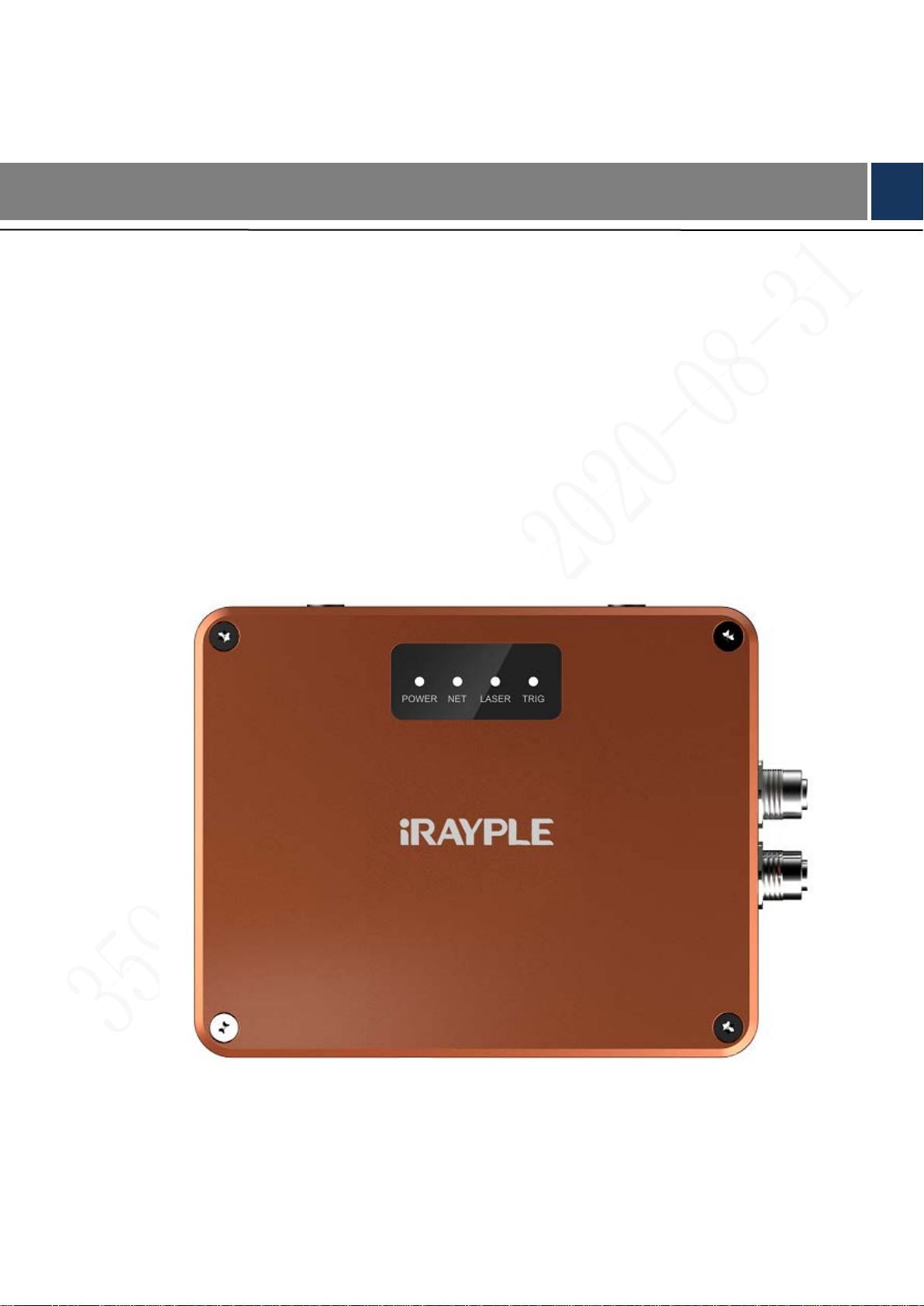
1 Product introduction ............................................................................................................................................ 1
1.1 Product introduction .................................................................................................................................... 1
1.2 Product feature............................................................................................................................................. 2
1.3 Packing list .................................................................................................................................................. 3
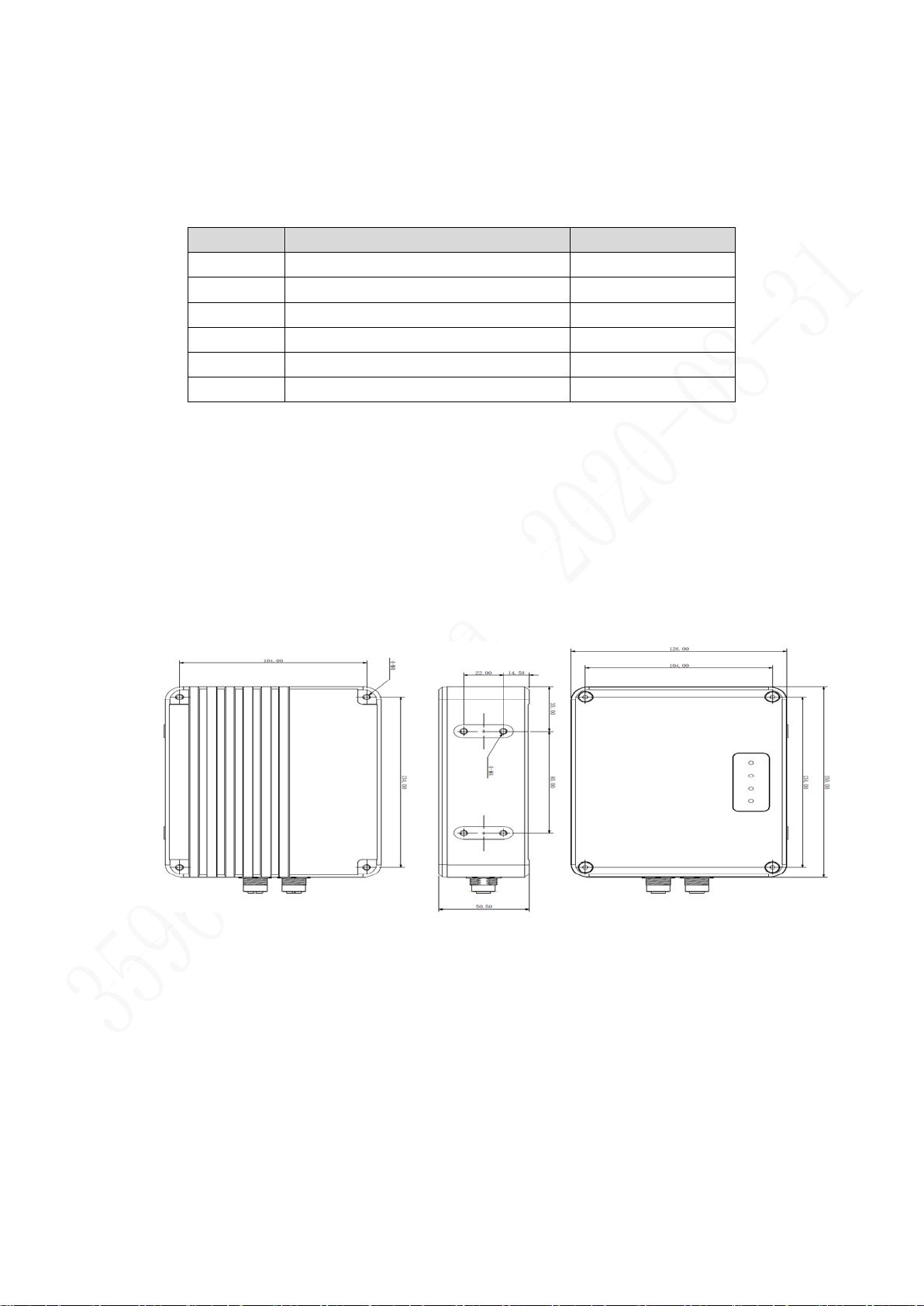
1.4 Product structure.......................................................................................................................................... 3
1.4.1 Product dimension............................................................................................................................ 3
1.4.2 Product interface............................................................................................................................... 4
1.5 Electrical specification................................................................................................................................. 7
2 Network............................................................................................................................................................... 17
3 Product installation ............................................................................................................................................ 18
4 Camera operation............................................................................................................................................... 19
4.1 Install the client.......................................................................................................................................... 19
4.2 Configuration guidance ............................................................................................................................. 20
4.3 Connect and disconnect the camera........................................................................................................... 21
4.4 The camera functions................................................................................................................................. 22
4.5 Image display............................................................................................................................................. 23
5 Camera functions................................................................................................................................................ 26
5.1 DeviceControl............................................................................................................................................ 26
5.2 TransportLayerControl .............................................................................................................................. 27
5.3 NTPcontrol ................................................................................................................................................ 28
5.4 TriggerControl........................................................................................................................................... 29
5.5 MonoCameraControl................................................................................................................................. 29
5.5.1 MonoCameraISPControl ................................................................................................................ 30
5.5.2 MonoCameraExposureControl....................................................................................................... 30
5.5.3 MonoImageFormatControl............................................................................................................. 31
5.6 ColorCameraControl.................................................................................................................................. 31
5.6.1 ColorCameraISPControl................................................................................................................. 32
5.6.2 ColorCameraExposureControl........................................................................................................ 32
5.6.3 ColorImageFormatControl.............................................................................................................. 33
5.7 VisionControl............................................................................................................................................. 33
5.8 BinocluarControl ....................................................................................................................................... 34
5.9 3DLocationControl.................................................................................................................................... 35
5.10 Digital IO Control.................................................................................................................................... 36
5.11 InputIOControl......................................................................................................................................... 37
5.12 LaserControl............................................................................................................................................ 37
5.13 UserSetControl ........................................................................................................................................ 38