LOW FLUE DRAUGHT SYMPTOMS: DIFFICULT TO LIGHT AND SMOKE COMING INTO THE ROOM.
CAUSE REMEDY
Cold chimney Line the chimney
Chimney too short Extend the chimney
Down draught Relocate/extend chimney terminal. Fit an anti down draught cowl.
Chimney diameter too large Line the chimney
Chimney obstruction Clear/sweep the chimney
Restricted air supply Check for competing draughts (other chimneys, extractor hood/fans).
Fit an air vent if the room is sealed.
HIGH FLUE DRAUGHT SYMPTOMS: FIRE DIFFICULT TO CONTROL, FUEL WILL NOT LAST, COOKING TOO HOT, APPLIANCE DAMAGE, CHIMNEY FIRE.
External wind conditions combined
with chimney terminal. Fit stabiliser cowl. Fit flue draught stabiliser.
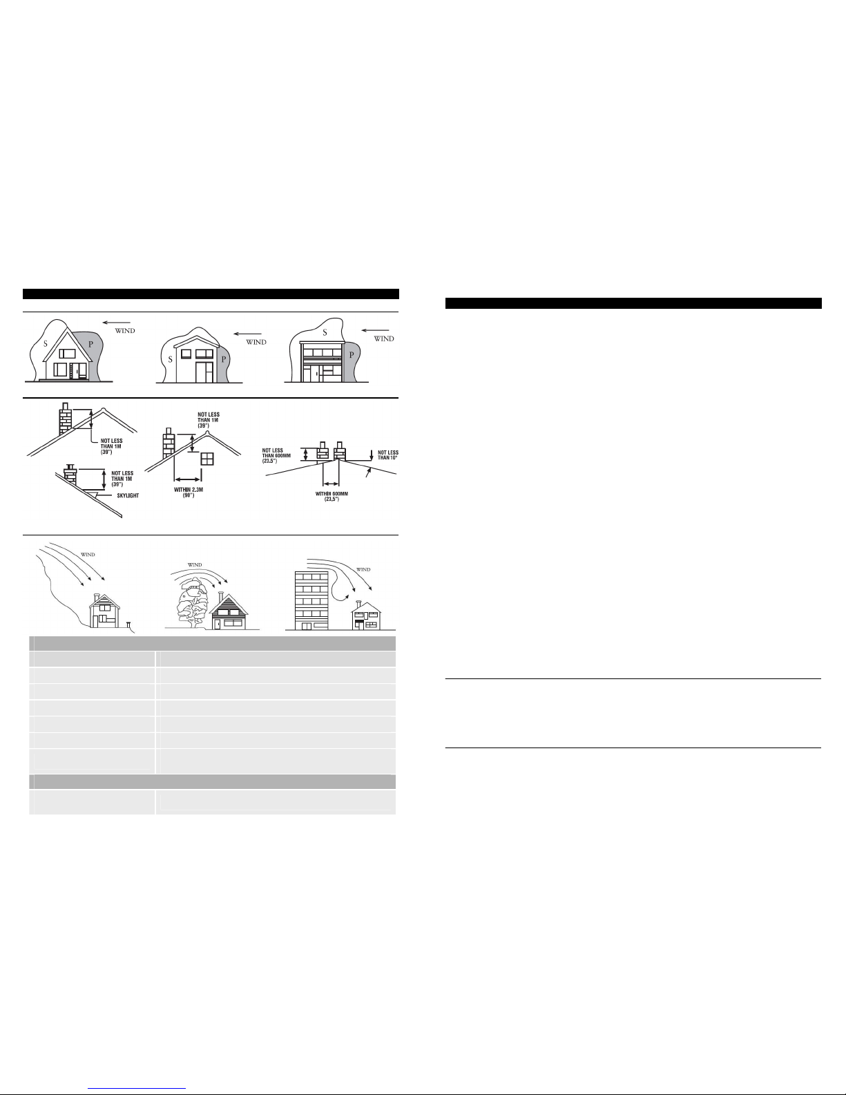
CHIMNEY AND FLUE
Pressure and suction zones created by wind
The position of chimney outlets
Potential causes of down draught
6
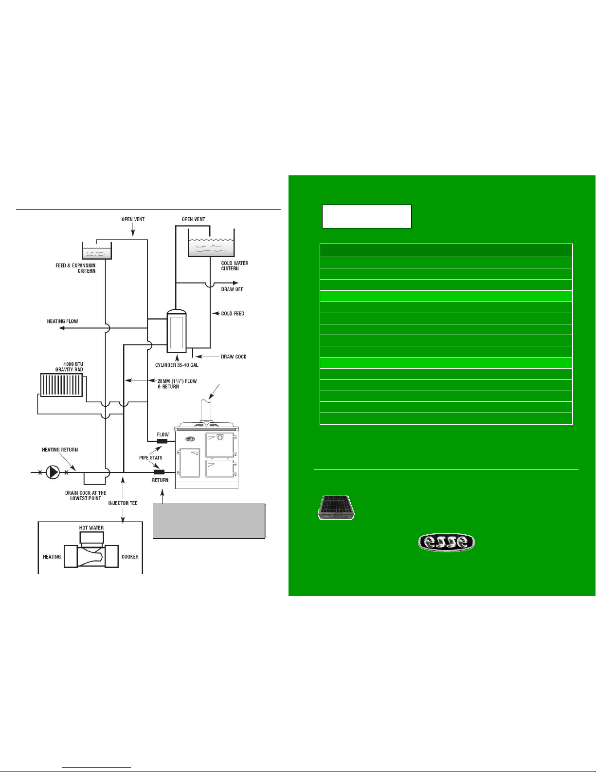
HOT WATER SYSTEMS
The connections will be supplied by your installer.
Water connections: There are two water flow connections and 2 water return connections. One of each on the left
hand side of the cooker and one of each at the rear of the cooker. All 4 connections are Rp1 (1’’ BSP female). 2 –
1’’ BSP plugs are supplied to blank off any unused connections. The storage cylinder should be 30-gallon nominal
capacity insulated to prevent heat loss and as close to the cooker as possible. Follow general notes below, item (B)
(6), (7) & (8).
These appliances are not suitable for use with sealed (pressurised) systems.
GENERAL NOTES ON WATER SYSTEM
1. The cooker will produce hot water at different rates depending on how it is operated. See ‘Heat output to
water’ below. A thermostat is fitted.
2. The system must be designed to cope with loads between the maximum and minimum output.
3. An indirect storage cylinder is essential for domestic hot water supply, irrespective of whether the water
supply is hard or soft. Minimum capacity is 30 gallons. Cylinder should be as close to cooker as possible.
4. The central heating circuit may be gravity circulation, but a pump system is preferred. To allow heat from
the boiler to be absorbed should there be a pump stoppage on an accelerated circuit, the primary domestic
supply must be gravity operated.
5. Installation as a central heating system alone, i.e. without a domestic supply, is not recommended as the
boiler will produce heat when the cooker is in use, irrespective of central heating demand, and primary
absorption must be provided.
6. Whichever system is chosen the layout must follow established heating engineering practice. To avoid
trapping air in the boiler a 1’’ BSP connection must be used on the flow trapping, and any reduction in pipe
size thereafter being made on a vertical rising pipe. The cooker must be level when fitted and the flow pipe
must rise from the boiler. A drain cock must be fitted on the lowest point of the return pipe and a vent to
atmosphere at the highest point of each circuit.
7. The cylinder and pipe work should be lagged to avoid heat loss.
8. The static head must not exceed 60 feet of water.
9. The static head must not exceed 2 bar.
The maximum output is 9.7kW (33.100Btu/l) in winter configuration and 3.7kW (12.600Btu/l) in summer
configuration. Installation procedure should follow the above, the cylinder being as near the cooker as it is possible
to avoid long pipe runs and subsequent heat loss.
If the appliance is to be fitted onto an existing water system then it must be power flushed prior to the
commissioning of the unit inhibitor re-added. Failure to carry out this operation will seriously affect boiler
performance and negate any warranty claim.
HEAT OUTPUT TO WATER
POWER FLUSH. WATER SYSTEMS