Essilor AKR 750 User manual

Auto kerato refractometer
Maintenance Manual
V1 –09/2016

1
Contents
1External View................................................................................................................. 2
2Internal Structural Diagram......................................................................................... 3
3Measurement Principle.................................................................................................. 4
4Block Diagram................................................................................................................ 5
5Connection Diagram ...................................................................................................... 6
6Wiring Diagram.............................................................................................................. 9
7Troubleshooting............................................................................................................ 11
8Cleaning of the Parts that Eyes Touch to, the Accessory Model Eye ASSY ............ 32
9Functional Check ......................................................................................................... 33
10 About Maintenance Mode ........................................................................................... 34
11 Evaluation of Freeze Image......................................................................................... 45
12 Replacement Procedure of Each Unit......................................................................... 47
13 Software update procedure………………………………………………………………...61
14 Parking mode………………………………………………………………………………...64

2
1 External View
Code
Name
16
LCD cover
17
Measurement start switch
18
Joystick handle
19
Power supply switch
20
USB terminal
21
RS232C terminal
22
Fuse holder
23
Power plug connector
24
Rating plate
25
Chin holder
26
Eye mark
27
Chin rest ASSY
28
Face cover
29
Head rest rubber
Code
Name
1
LCD monitor
2
Main unit cover L
3
Main unit cover R
4
Clear switch
5
3D AUTO / MANUAL switch
6
CUSTOM switch
7
Measurement mode select switch
8
Menu switch
9
Print switch
10
Printer cover
11
Chin holder vertical movement switch
12
Rubber leg
13
Base cover 2
14
Base cover 1
15
Front cover

3
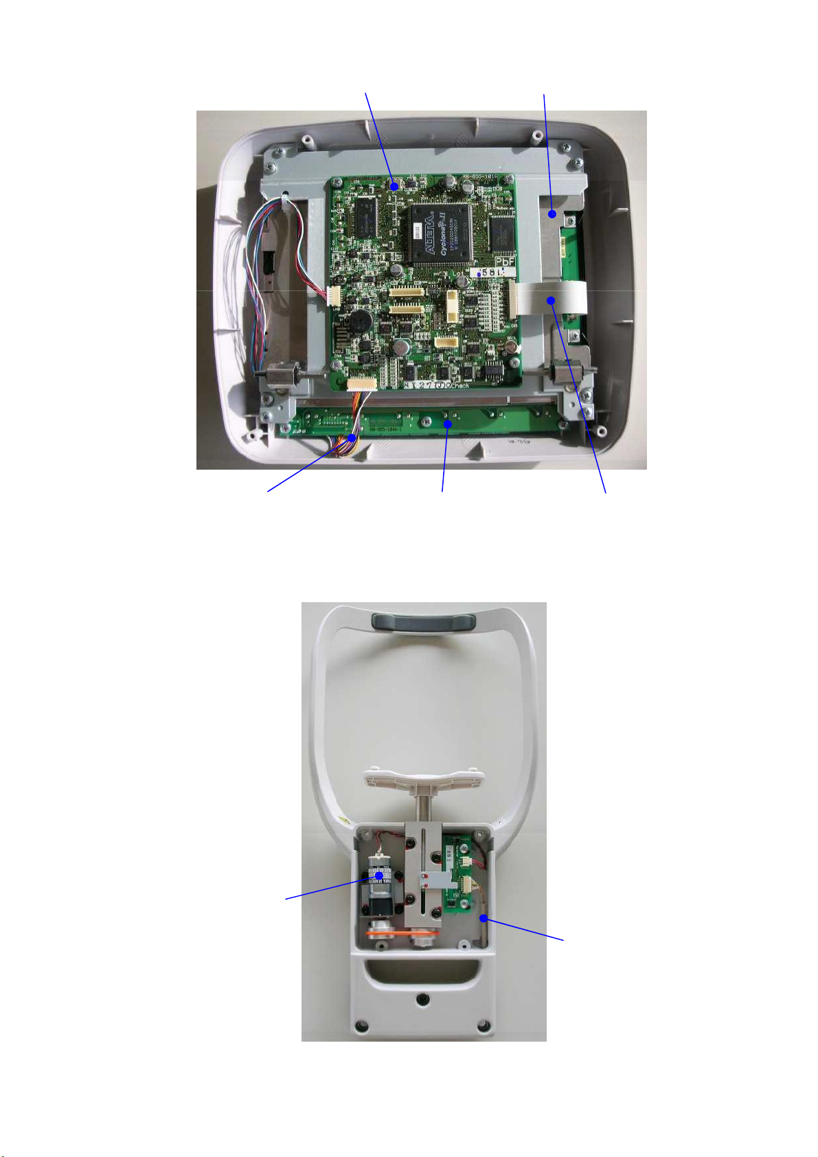
2 Internal Structural Diagram
Code
Name
16
Switching power supply
17
Vertical positioning mechanism
18
Power supply board ASSY
19
Vertical detection sensor board
20
Backside protection cover
21
Vertical movement motor
22
Back and forth positioning mechanism
23
Back and forth detection sensor board
24
Horizontal positioning mechanism
25
Horizontal detection sensor board
26
Measuring window ring
27
Head rest rubber
28
Chin rest ASSY
29
Chin rest vertical positioning mechanism
Code
Name
1
Measurement unit
2
Optical control board ASSY
3
Optical ASSY cover
4
PD sensor board
5
Horizontal movement motor
6
LCD cover
7
LCD
8
Main control board ASSY
9
Operation switch board ASSY
10
Printer control board
11
Printer
12
Back and forth movement monitor
13
Foreside protection cover
14
Measurement start switch
15
Joystick handle
4
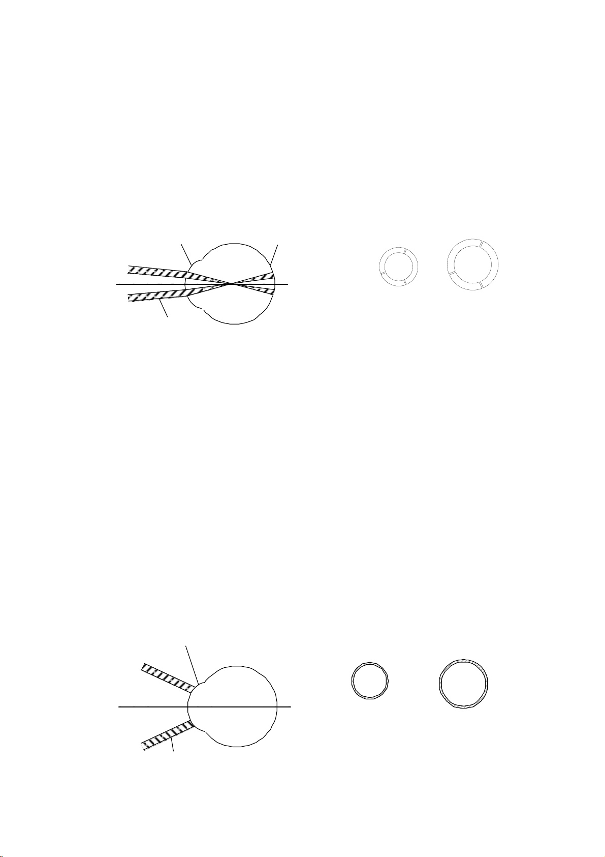
3 Measurement Principle
1) Measurement of eye refraction
A measurement pattern for measurement of eye refraction is projected to an eyeground
to be measured.
The projected pattern changes its size depending on the eye’s refractive power. The
reflected light of this eyeground image is led to the sensor through the measurement
system. The detected data is stored in the frame memory and conducted pattern
analysis by image processing to calculate values of S,C, and A.
Cornea Eyeground
Projected light Hyperopia Myopia
Eye to be measured Projected patterns on the sensor
Rough refractive power (temporary measurement) is calculated by the first
measurement and auto fogging operation and focusing operation of eyeground images
are started based on the data. Then, the actual measurement is started and the
refractive power of the eye to be measured is calculated and displayed.
2) Measurement of corneal curvature radius
A ring-shaped measurement pattern in projected onto a cornea of an eye to be
measured.
The pattern projected on the cornea varies its size depending on the corneal curvature
radius. The projected light is led to the sensor through the cornea measurement
system. The detected data is stored in the frame memory and conducted pattern
analysis by image processing to calculate values of R1, R2, and A.
Cornea
Corneal curvature
radius : small
Corneal curvature
radius : large
Projected light
Eye to be measured
Projected patterns on the sensor

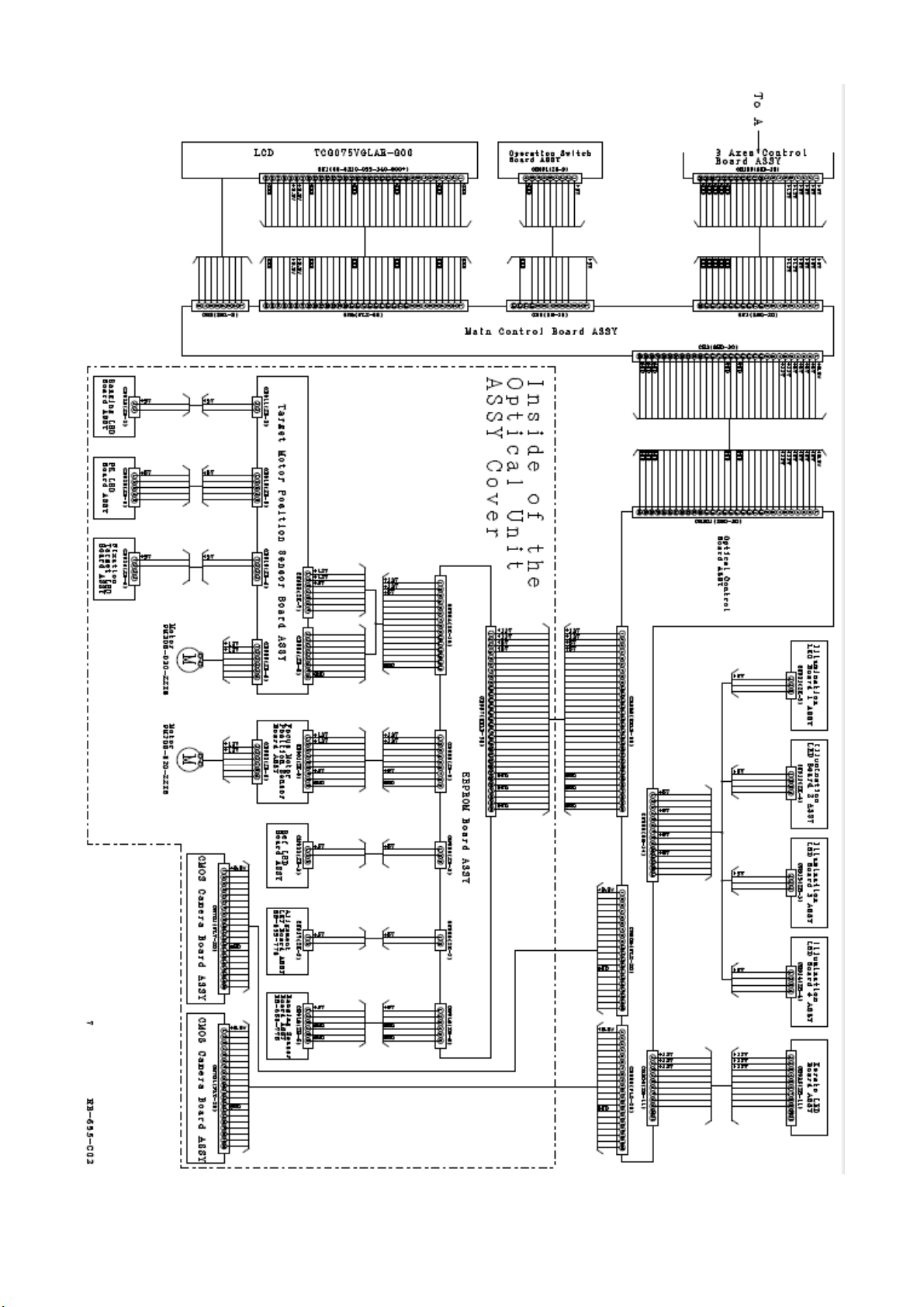
4 Block Diagram

8

9
6
Wiring Diagram
6-1 Overall view
Optical unit ASSY
Optical control board
CMOS harness LCD
Chin rest ASSY
3 axes control board Chin holder vertical movement
switch board ASSY
Joystick ASSY
1
0
6-2 LCD ASSY diagram
Main control board LCD
Operation switch harness Operation switch
board ASSY
LCD harness
6-3 Chin rest ASSY diagram
Chin rest motor ASSY
Chin rest sensor harness

10
6-4 Base unit wiring diagram
Switching power supply PC I/F board ASSY Power supply board ASSY
Power supply switch Fuse holder

11
7
Troubleshooting
7-1 General description of boards
7-2 Error message ‘RETRY’appears
7-3 Error message ‘EEPROM fault’appears
7-4 Error message ‘Motor fault’appears
7-5 Error message ‘Printer head heat over’appears
7-6 Error message ‘Paper empty’appears
7-7 Error message ‘Printer cutter fault’appears
7-8 Nothing is displayed on the screen when turning the power on
7-9 No responses even though pressing switches
7-10
Result is not printed out/printout is not normal
7-11
Ref measurement LED does not light up
7-12 Cannot see the fixation target
7-13 Illumination LED does not light up
7-14
Kerato LED does not light up
7-15
The fixation target LED for P.K. measurement does not light up
7-16
3 axes motor does not work even though operating a joystick
7-17 Chin rest does not move
7-18 Cannot communicate with PC
7-19
No power outlet
7-20
Abnormal measurement value of model eye ASSY

12
7-1 General description of boards
This product is composed with peripheral devices, such as 4 control boards, LED, and sensor etc.
The micro controller is mounted on 4 control boards below and they work with the instruction
from the main control board (UART communication). When the green LED is blinking on the
optical control board or 3 axes control board, it is in communication with the main control board.
The main functions of the boards are shown below.
1
Main control board:
CMOS camera control, LCD control, operation switch control,
measurement switch control, image processing, alignment control
2
Optical control board:
Control of each LED board in the optical unit ASSY, control of the
motor in the optical unit ASSY, ranging sensor control
(Green LED on the optical control board blinks when the main control
board and the optical control board are in communication.)
3
3 axes control board:
X,Y, and Z axes motor control, chin rest control, joystick control
(Green LED on the 3 axes control board blinks when the main control
board and 3 axes control board are in communication.)
4
Printer control board:
Printing of the printer, feeding paper control, cutter control
5
Power supply board:
Generate 5V and 12V from 24V output from the switching power supply
6
PC I/F board:
Control of USB and RS-232C

13
‘RETRY’ is displayed.
7-2 Error message ‘RETRY’appears.
The main causes when the error message ‘RETRY’appears:
・When the image is not caught accurately because of the condition of the examinee (he/she
blinked or is not looking at the target etc.)
・Alignment is not adjusted correctly
・Failure of the main control board
・Failure of the optical control board or CMOS camera
・Failure of the measurement LED
YES
Check the condition of the eye to be measured.
Abnormal ①
Measurement cannot be taken in case
of disorder such as cataracts etc.
Abnormal ②
If the pupil is smaller than the reticle
mark, the measurement might not be
be taken.
Darken the surround and try to take a
measurement again.
【Refer to 11-3】
Normal
Realign correctly and take
a measurement again.
【Refer to ‘6.2 Alignment’of
the Operation Manual】
Can a model eye be measured?
NO
Evaluate the Freeze Image.
【Refer to 11】

14
7-3 Error message ‘EEPROM fault’appears.
The main causes when the error message ‘EEPROM fault’appears:
・Failure of the optical control board
・Failure of the EEPROM board
Replace the optical control board.
Does the message still appear?
Replace the optical unit ASSY.
Does the message still appear?
NO
YES
NO
YES
Replace the main control board
OK
‘EEPROM fault’ is displayed.

15
7-4 Error message ‘Motor fault’appears.
The main causes when the error message ‘EEPROM fault’appears:
・Failure of the motor assy, the optical control board, or EEPROM board
・Failure of the forcus motor positioning sensor boardor, the target motor positioning sensor
board
Does the message still appear?
Does the message still appear?
‘Motor fault’ is displayed.
Replace the optical control board.
NO
YES
Replace the optical unit ASSY.
NO
YES
Replace the main control board.
OK

16
7-5 Error message ‘Printer head heat over’appears.
The main causes when the error message ‘Printer head heat over’appears:
・Failure of the printer
・Failure of the printer control board
Replace the printer control board.
Does the message still appear?
‘Printer head heat over’ is displayed.
Replace the printer.
NO
YES
OK

17
Are there any papers in the printer?
‘Paper empty’ is displayed.
7-6 Error message ’Paper empty’appears.
The main causes when the error message ‘Paper empty’appears:
・No printer papers in the printer
・Failure of the printer
・Failure of the printer control board
NO
YES
YES
Replace the printer
Replace the printer control board.
Does the message still appear?
NO
YES
OK
Are printer papers set properly?
Reset the papers.
NO
Set the papers.

18
‘Printer cutter fault’ is displayed.
7-7 Error message ‘Printer cutter fault’appears.
The main causes when the error message ‘Printer cutter fault’appears:
・The printer paper is stuck in the cutter portion
・Failure of the printer
・Failure of the printer control board
NO
Replace the printer.
Replace the printer control board.
Does the message still appear?
NO
YES
OK
Are the printer papers stuck
in the printer portion?
Remove the paper.
YES

20
Nothing is displayed on the screen.
7-8 Nothing is displayed on the screen when turning power on.
The main causes when nothing is displayed on the screen when you turn the power on:
・Blowout of the fuse
・Failure of the switching power supply
・Failure of the power supply board
・Failure of the main control board
・Failure of LCD or LCD harness
YES
Is LCD harness normal?
Replace the LCD harness.
Replace the LCD.
Is screen display normal?
Replace the main control board.
Is screen display normal?
NO
YES
YES
NO
NO
YES
OK
Does LED next to the operation switch blink
and 3 axes motor start initializing when the
power is on?
NO
No power outlet
【Refer to 7-19】
Table of contents
Other Essilor Medical Equipment manuals

Essilor
Essilor CORNEA 550 User manual

Essilor
Essilor WAM700 User manual

Essilor
Essilor MYOPIA EXPERT 700 User manual

Essilor
Essilor SL 350 User manual

Essilor
Essilor CS pola 600 User manual

Essilor
Essilor PRO-E 600 User manual

Essilor
Essilor ALM 700 User manual

Essilor
Essilor AKR 550 User manual

Essilor
Essilor PSL classic User manual

Essilor
Essilor CS550 User manual
Popular Medical Equipment manuals by other brands


Freedom Innovations
Freedom Innovations SLALOM SKI Instructions for use

Beurer medical
Beurer medical IPO 61 Instructions for use

Ultra Ankle
Ultra Ankle Ultra CTS Fitting instructions

telli health
telli health BM1000 user manual

AbbVie
AbbVie Cross Body Pack Instructions for use

Fazzini
Fazzini F-18 Battery Instructions for use