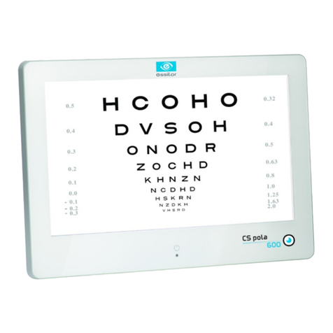
Essilor CS550 User manual

www.essilor-instruments.com
User Manual

CONTENTS
I. INTRODUCTION 5
1. Outline of pro uct 6
2. Classifications 6
II. SAFETY INFORMATION 7
1. Intro uction 8
2. In ications for use 8
3. Safety symbols 9
4. Environmental factors 10
5. Safety precautions 12
III. FEATURES 13
IV. NOTES FOR USING THE INSTRUMENT 15
V. CONFIGURATION 17
VI. INSTALLATION 21
1. Instruction for wall mounting 22
2. Viewing istance (LCD isplay position) 22
3. Feature set 23
a. Feature set mo e menu 23
b. Feature set mo e setting metho 23
c. Feature set mo e isable 24
. Function set overview 24
VII. TEST METHOD 31
VIII. REMOTE CONTROL FUNCTION 37
1. General function 38
2. Sli e function 39
IX. HOW TO RECHARGE A REMOTE CONTROL 41
X. CLEANING THE PRODUCT 43
XI. TROUBLESHOOTING GUIDE 45
XII. ENVIRONMENTAL CONDITIONS 47
XIII. SPECIFICATIONS 49
XIV. COMPONENTS LIST 51
1. Stan ar accessories 52
2. Optional accessories 52
XV. SERVICE INFORMATION 53
1. Repair 54
USER MANUAL> CONTENTS

I. INTRODUCTION

1. OUTLINE OF PRODUCT
CS550 is an automatic visual acuity system, stan -alone type, which isplays broa range of charts, base
on LCD panel, inclu ing re /green for the eye optometry.
The chart rotation for CS550 can be performe by either wire or wireless remote control or by external
evices by control box of Digital Phoropter.
Unlike existing chart projector, CS550 is able to provi e wi er range of charts (more than 100 kin s of
general an special charts) on LCD panel an the pro uct can be a juste at the level of the patients for
precise examination.
2. CLASSIFICATIONS
•Classification of equipment: Class I
•Applie part of equipment: no applie part
•Protection against electric shock: Class I
•Protection against harmful ingress of water: or inary (IPX0)
•Metho of sterilization: not applicable
•Stability of use in an oxygen rich environment: not suitable
•Mo e of operation: continuous operation
CS550 - Chart system > V1 - 10-2015
6
USER MANUAL> I. INTRODUCTION

II. SAFETY INFORMATION

1. INTRODUCTION
Safety is everyone's responsibility. The safe use of this equipment is largely epen ent upon the installer,
user, operator, an maintainer. It is imperative that personnel stu y an become familiar with this entire
manual before attempting to install, use, clean, service or a just this equipment an any associate
accessories. It is paramount that the instructions containe in this manual are fully un erstoo an followe
to enhance safety to the patient an the user/operator. It is for this reason that the following safety notices
have been place appropriately within the text of this manual to highlight safety relate information or
information requiring special emphasis. All users, operators, an maintainers must be familiar with an pay
particular attention to all Warnings an Cautions incorporate herein.
Accessory equipment connecte to the analog an igital interfaces must be certificate accor ing to the
respective IEC stan ar s (e.g. IEC 60950-1 for ata processing equipment an IEC 60601-1 for me ical
equipment). Furthermore all configurations shall comply with the system stan ar EN 60601-1:2006, Clause
16. Everybo y who connects a itional equipment to the signal input part or signal output part configures a
me ical system, an is therefore responsible that the system complies with the requirements of the system
stan ar IEC 60601-1:2005, Clause 16. If in oubt, consult the technical service epartment or your local
representative.
“Warning” in icates the presence of a hazar that coul result in severe personal injury, eath or
substantial property amage if ignore .
“Note” escribes information for the installation, operation, or maintenance of which is important but
hazar relate if ignore .
“Caution” in icates the presence of a hazar that coul result in minor injury, or property amage if
ignore .
This evice is compliant with marking.
Date of first marking: October 2015.
2. INDICATIONS FOR USE
The in ications for use inclu e the visual acuity for etermining patient objective refraction.
CS550 - Chart system > V1 - 10-2015
8
USER MANUAL> II. SAFETY INFORMATION

3. SAFETY SYMBOLS
The International Electro-technical Commission (IEC) has establishe a set of symbols for me ical electronic
equipment which classify a connection or warn of any potential hazar s.
The classifications an symbol are shown below.
I O I an O on power switch represent ON an OFF respectively
Attention, consult ACCOMPANYING DOCUMENTS
Alternating current
Direct current
I entifies the point where the system safety groun is fastene to the chassis. Protective
earth connecte to con uctive parts of Class I equipment for safety purposes.
Manufacturer
This evice is compliant with CE marking (Directive 93/42/CE). It is a class I accor ing to
rule 12 from Appen ix I.
Date of first marking Oct 2015.
or Follow operating instructions
Disposal of your ol appliance
•When this crosse -out wheele bin symbol is attache to a pro uct it means the
pro uct is covere by the European Directive 2012/19/EU.
•All electrical an electronic pro ucts shoul be ispose of separately from the
municipal waste stream via esignate collection facilities appointe by the
government or the local authorities.
•The correct isposal of your ol appliance will help prevent potential negative
consequences for the environment an human health.
•For more etaile information about isposal of your ol appliance, please contact
your city office, waste isposal service or the shop where you purchase the
pro uct
USER MANUAL> II. SAFETY INFORMATION
9
CS550 - Chart system > V1 - 10-2015

4. ENVIRONMENTAL FACTORS
Avoi the following environments for operation or storage.
Where the equipment is expose to water vapor.
Don't operate an equipment with a wet han .
Where the equipment is expose to irect sunlight.
Where the temperature changes extremely.
Normal operating temperature range is from 10°C to 40°C, humi ity is from 30% to 75%.
Where it is near the heat equipment.
Where the humi ity is extremely high or there is a ventilation problem.
Where the equipment is subject to excessive shocks or vibrations.
Where equipment is expose to chemical material or explosive gas.
Be careful not to be inserte ust, especially, metal.
Don't isassemble the pro uct or open. The warranty is voi .
Be careful not to close the fan locate on the lateral or back si e of the equipment.
Don't plug the AC power cor into the outlet before the connection between evices of the
equipment is complete .
This can generate the efect.
Pull out the power cor with hol ing the plug, not the cor .
To avoi the risk of electric shock, this equipment must only be connecte to supply mains with
protective earth.
CS550 shall be connecte to the separate power supply as supplie by ESSILOR with A apter
Technology Co., Lt , type ATM065-P120 I entifie .
Do not position the equipment to make it ifficult to operate the isconnection evice. (Appliance
coupler or separable plug).
Ahea of going into the iscar , ask way to o it or consult with selling agency.
This evice incorporates a lithium battery (BAT1) on the main boar , incorrect replacement of which
woul result in an unacceptable RISK. Therefore, replacement by ina equately traine personnel coul
result in a HAZARD (such as excessive temperatures, fire or explosion).
CS550 - Chart system > V1 - 10-2015
10
USER MANUAL> II. SAFETY INFORMATION

Do not place the multiple socket-outlet for CS550 system on the floor in or er to prevent liqui
penetration an amage to the pro uct.
CS550 system shall not be connecte with a itional multiple socket-outlets or extension cor s in
a ition to a esignate single multiple socket-outlet.
Maximum permissible loa of each socket-outlet use for the CS550 system, shall not be less than
60VA.
Do not connect the evice which is not a supplement of CS550 with the multiple socket-outlet of
CS550.
Multiple socket-outlet shoul be a groun ing-type an complie with IEC 60884-1.
View from A-A (male plug connected)
Connection of the plug shall be possible only by
using the tool.
1 : Male plug ME equipment
2 : Cover
3 : Spacer
4 : Plate fixe on MSO
5 : MSO
Avoi places where the ambient temperature falls below 10°C or excee s 40°C for normal operation, or
below -10°C or excee s 55°C (14°C-131°C) for transportation an storage. Humi ity shoul be maintaine
between 30 an 85% (Atmospheric pressure: 70 to 106 kPa) for normal operation, or between 10 an 95%
(Atmospheric pressure: 50 to 106kPa) for transportation an storage. Avoi environments where the
equipment is expose to excessive shocks or vibrations.
USER MANUAL> II. SAFETY INFORMATION
11
CS550 - Chart system > V1 - 10-2015

5. SAFETY PRECAUTIONS
This equipment has been evelope an teste accor ing to safety stan ar s as well as national an
international stan ar s. This guarantees a very high egree of safety for this evice. The legislator expects
us to inform the user expressively about the safety aspects in ealing with the evice. The correct han ling
of this equipment is imperative for its safe operation. Therefore, please rea carefully all instructions before
switching on this evice. For more etaile information, please contact our Customer Service Department or
one of our authorize representatives.
1. This equipment must not be use (a) in an area that is in anger of explosions an (b) in the
presence of flammable, explosive, or volatile solvent such as alcohol, benzene or similar chemicals.
2. Do not put or use this evice in humi rooms. Humi ity shoul be maintaine between 30 an 75%
for normal operation. Do not expose the evice to water splashes, ripping water, or spraye water.
Do not place containers containing flui s, liqui s, or gases on top of any electrical equipment or
evices.
3. The equipment must be operate only by, or un er irect supervision of a properly traine an
qualifie person.
4. Mo ifications of this equipment may only be carrie out by traine service technicians or other
authorize persons.
5. Customer maintenance of this equipment may only be performe as state in the user's manual an
service manual. Any a itional maintenance may only be performe by traine service technicians or
other authorize persons.
6. The manufacturer is only responsible for effects on safety, reliability, an performance of this
equipment when the following requirements are fulfille : (1) The electrical installation in the
respective room correspon s to the specifications state in this manual an (2) This equipment is
use , operate , an maintaine accor ing to this manual an service manual.
7. The manufacturer is not liable for amage cause by unauthorize tampering with the evice(s). Such
tampering will forfeit any rights to claim un er warranty.
8. Interconnecte equipment to this equipment shall be complie with the applicable international
stan ar s, e.g. IEC/EN 60950-1 for I.T equipment.
9. Only persons who have un ergone proper training an instructions are authorize to install, use,
operate, an maintain this equipment.
10.Keep the user's manual an service manual in a place easily accessible at all times for persons
operating an maintaining the equipment.
11.Do not force cable connections. If a cable oes not connect easily, be sure that the connector (plug) is
appropriate for the receptacle (socket). If you cause any amage to a cable connector(s) or
receptacle(s), let the amage(s) be repaire by an authorize service technician.
12.Please o not pull on any cable. Always hol on to the plug when isconnecting cables.
13.This equipment may be use for the international application relate to (*Usages of Device) accor ing
to this manual.
14.Before each operation, visually check the equipment for exterior mechanical amage(s) an for
proper function.
15.Do not cover any ventilation gri s or slits.
16.Imme iately turn off an unplug any equipment that gives off smoke, sparks, strange noises or
o ors.
CS550 - Chart system > V1 - 10-2015
12
USER MANUAL> II. SAFETY INFORMATION

III. FEATURES

Re & Green reverse CS550 system enables a user to reverse all kin s of Re /Green chart
by using Black & White reverse button on the remote control.
Animation function CS550 system has a Animation function for making a chil
concentrate on the chart uring the test an it easy to examine.
Contrast a justment
CS550 can ecrease the contrast level in or er to examine eye-sight
un er low contrast con ition. CS550 system enables a user to select
contrast sensitivity (75%, 50%, 40%, 30%, 20%, 10%, 7.5%, 5%,
3%, an 1.5%) on a screen an also each strength of the contrast
sensitivity can be shown on the screen of remote control that is use
uring a vision test with a cataract surgery patient by a justing opto-
type contrast sensitivity.
Black & White reverse
CS550 system enables a user to test conveniently by using Black &
White function which lasik & cataract patients can recognize in bright &
ark places.
Ran om function
Ran om function of CS550 system is esigne to stop a visual test
error, when an examinee memorizes specific test types an irections.
A user can test conveniently by freely changing “Numbers, English,
Korean, Lan olt, Snellen, Chil ren”. Some charts such as Lan olt,
Number can be rotate by remote control.
Re /Green filter for color
epth a justment
CS550 system enables a user to a just to Re /Green filter
concentration from the 0 to the 31 steps. It applies to all kin s of
Re /Green chart.
Mirror function
The Mirror function is a e in CS550 system to let it installe at less
than 1.5m of narrow space an a user can easily select the function at
his convenience.
Clock ial rotating
7 kin s of clock ials are rotating step by step by using Up/Down
button on the remote control. It also reverses the Black & White by
using the Black & White reverse button on the remote control.
CS550 - Chart system > V1 - 10-2015
14
USER MANUAL> III. FEATURES

IV. NOTES FOR USING THE INSTRUMENT

1. Do not hit or rop the instrument. The instrument may be amage if it receives a strong impact. The
impact can amage the function of this pro uct. Han le it with care.
2. Keep this pro uct from vibration.
3. Exposure of irect sunlight or very bright in oor lights can affect the result of measurements.
4. Don't use organic solution such as alcohol, thinner, benzene, etc. to clean the surface of this
instrument. It may amage the pro uct.
5. Disconnect the power supply an consult the ealer when there is smoke, strange o ors, or noise
while working.
CS550 - Chart system > V1 - 10-2015
16
USER MANUAL> IV. NOTES FOR USING THE INSTRUMENT

V. CONFIGURATION

CS550 is mainly consists of the components as below.
Name Function
1: LCD isplay monitor Displaye the chart for test by using the graphic-processing function on
computer
2: IR receive win ow Display chart to receive the infrare win ows from remote controller
3: AC power inlet A part of the power supply cables an connections
4: RS-232 port (USB Type) Serial port for communicating with external evices
5: APH500 port Connector for ata communication with APH500
6: Power On/Off switch Power On/Off switch
7: Function button Set parameter on the screen
8: SD car cover Slot cover of chart ata or image storage SD car
If you want to connect the input / output signal ports an other evices that must meet IEC stan ar s
(IEC60950 IT equipment, IEC60601 me ical equipment).
If any oubt please contact your local technical support or your authorize istributor.
CS550 - Chart system > V1 - 10-2015
18
USER MANUAL> V. CONFIGURATION

1 IR communication win ow (sen ing signal to CS550)
2 LCD screen: isplay charts (optotype)
3 Power button: power On/Off
4 Chart changing button: change the chart on LCD
5 Masking button (Horizontal): isplay charts horizontally
6 Masking button (Vertical): isplay charts vertically
7 Move button (left an right): isplay the chart showing on LCD with moving towar left or right
8 Single masking button: isplay a chart symbol one by one
9 Up/Down button: change the chart on LCD by pressing Up/Down button
10 Optotype select button: select one among Number, Snellen, English, Korean
11 Contrast button: a justing the contrast level
12 Sli e button: select one among color blin ness test, contrast test an other images
13 Black/White reverse button: chart on LCD can be reverse with Black an White
14 Ran om button: change the array of optotype
15 Program A/B button: program can be change with following sequence (A > B > General >
Reverse)
16 Program sen ing button: isplay the programme chart in sequence uring operation
17 Program reverse sen ing button: isplay the programme chart right ahea
18 Re /Green filter button: isplay the special chart a apte with Re /Green filter
USER MANUAL> V. CONFIGURATION
19
CS550 - Chart system > V1 - 10-2015

19 Mini USB socket: for operating CS550 an for charging the remote control battery
20 LED: in icating the status of electric charge
21 Loop part: connect the string with this part
22 Battery housing
22-1 J6 connector removes
22-2 Cable assy unplug
CS550 - Chart system > V1 - 10-2015
20
USER MANUAL> V. CONFIGURATION

VI. INSTALLATION

1. INSTRUCTION FOR WALL MOUNTING
Unsecure pro uct coul be islo geg an fall which causes injury to either patient or examiner.
All cables relate to the pro uct shall be han le with care for preventing the examiner or the patient
from any kin s of angers.
Be sure that the position you choose to mount the pro uct shall be within the reach of a power outlet.
•Fin an appropriate point on the wall which will support the pro uct, which will hang from the wall-
mount bracket attache to the wall.
•Make sure that the refraction istance meets the requirements for either irect-view or mirror
arrangement.
•Level the supplie wall mount bracket with the metal tabs facing up an out on your wall an mark
the holes on the installation.
•Place the wall mount bracket on the wall, an screw or tap the screws (nail) into the holes. Hang the
pro uct by lining up the holes on the back of unit with the metal tabs of the wall mount bracket an
hang the unit on these tabs.
Do not over rive the inserts into the wall.
2. VIEWING DISTANCE (LCD DISPLAY POSITION)
•As operation by remote control is available, an operator can examine the patient checking the proper
change of the charts.
•Please put the pro uct so that the center of the LCD screen is at the level of patient's eyes as this
pro uct is not affecte by illumination.
CS550 - Chart system > V1 - 10-2015
22
USER MANUAL> VI. INSTALLATION
Table of contents
Other Essilor Medical Equipment manuals

Essilor
Essilor ALM 700 User manual

Essilor
Essilor CS pola 600 User manual

Essilor
Essilor CORNEA 550 User manual

Essilor
Essilor WAM700 User manual

Essilor
Essilor SL 350 User manual

Essilor
Essilor PRO-E 600 User manual

Essilor
Essilor AKR 550 User manual

Essilor
Essilor MYOPIA EXPERT 700 User manual

Essilor
Essilor PSL classic User manual

Essilor
Essilor AKR 750 User manual
Popular Medical Equipment manuals by other brands

Plinth 2000
Plinth 2000 93C Service manual

Blatchford
Blatchford 239130 Instructions for use

Medline
Medline EntraFlo Operating instruction guide

Brainlab
Brainlab Robotics Hardware user's guide

Fresenius Kabi
Fresenius Kabi Volumat MC Agilia Quick reference guide

3M
3M Curing Light 2500 M 5560 Instructions for use