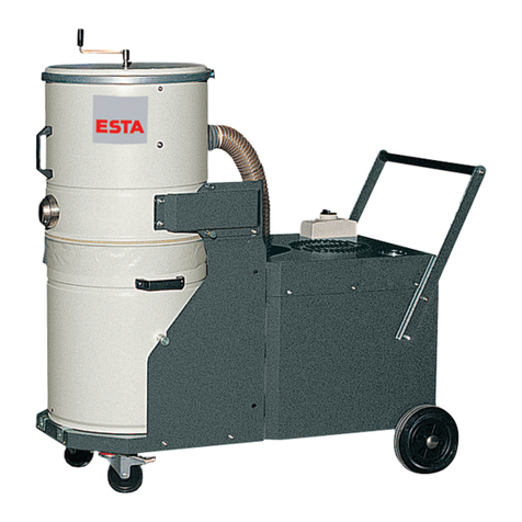
Esta DUSTOVAC 5.5 FM User manual

.
Operating manual
DUSTOVAC
Item No. 83.109 (DUSTOVAC 5.5 FM)
Item No. 83.110 (DUSTOVAC 5.5FA)
Item No. 83.112 (DUSTOVAC 5.5 Jet)
Item No. 83.103 (DUSTOVAC 7.5 FM)
Item No. 83.105 (DUSTOVAC 7.5 FA)
Item No. 83.107 (DUSTOVAC 7.5 Jet)
Item No. 83.104 (DUSTOVAC 13.0 FM)
Item No. 83.106 (DUSTOVAC 13.0 FA)
Item No. 83.108 (DUSTOVAC 13.0 Jet)
Do not use this device unless you have
read the user manual and understand it.
Original version of the German operating manual
83107-08-01

Symbols
2 DUSTOVAC 83107-52-01
Warnings and safety instructions
Electrical current hazard
Note
Reference to ESTA customer service
Reference to legal regulations

Contents
83107-52-01 DUSTOVAC 3
Contents
Contents ..................................................................................................................................... 3
1. General safety notes ........................................................................................................... 4
2. Preventing mechanical hazards ......................................................................................... 7
3. Preventing electrical hazards ............................................................................................. 7
4. Preventing dust hazards ..................................................................................................... 7
5. Intended use ........................................................................................................................ 8
6. Technical data and description .......................................................................................... 9
6.1 Technical data .................................................................................................................... 9
6.2 Functional description ....................................................................................................... 10
7. Delivery and commissioning ............................................................................................ 11
7.1 Delivery and transport ...................................................................................................... 11
7.2 Commissioning ................................................................................................................. 11
8. Maintenance & troubleshooting ....................................................................................... 13
8.1 Maintenance instructions .................................................................................................. 1 3
8.2 Inspection and maintenance intervals .............................................................................. 14
8.3 Troubleshooting ................................................................................................................ 15
9. Monitoring the minimum airflow volume ......................................................................... 16
10. Cleaning ............................................................................................................................. 16
10.1 Manual cleaning ............................................................................................................. 16
10.2 Pneumatic compressed air cleaning ............................................................................... 17
10.3 Jet cleaning .................................................................................................................... 17
10.4 Cleaning the bypass valve .............................................................................................. 18
10.5 Filter replacement ........................................................................................................... 18
10.5.1 For devices with manual cleaning ................................................................................ 18
10.5.2 For devices with pneumatic filter cleaning ................................................................... 19
10.5.3 For devices with jet cleaning........................................................................................ 19
11. Disposal .............................................................................................................................. 20
11.1 Disposing of collected dust materials ............................................................................. 20
11.2 Disposing of the exhaust device ..................................................................................... 21
12. Optional equipment ........................................................................................................... 22
13. Declaration of conformity ................................................................................................. 23
Notes ......................................................................................................................................... 24

Safety instructions
4 DUSTOVAC 83107-52-01
1. General safety notes
Before operation, all persons who are to use the dust extractor or perform
maintenance on it must be provided with information, instructions and training in
using the device and on the substances for which it is to be used, including the
procedure for safe disposal of the collected material. Responsibilities must be
clearly established for the following:
Installation
Start-up
Operation
Maintenance and repair
The device must be used only by persons who have been instructed in its
handling and are explicitly authorized to use it.
Always keep the operating manual at the place where the dust extractor is being
used, so that it can be seen by personnel at all times.
The dust extractor is intended only for dry cleaning and must not be used or
stored outdoors or under wet conditions.
Only original ESTA replacement parts must be used; use of other products will
void the warranty.
During exhaust, the volume flow returned from the dust extractor into the room
must be no more than 50% of incoming air. With free room ventilation, the
incoming airflow must equal the room volume every hour. This means that the rate
of air replacement must be once per hour.
Incoming air flow [m³/h] = room volume [m³] air replacement rate [1/h]
Example:
When the ESTA dust extractor is operating at the nominal airflow volume of 850
m³/h, the same volume of fresh air must therefore be fed in. This occurs with
natural ventilation if the volume of the work room is 850 m³ (e.g., 212 m² surface
with a 4 m ceiling height).
Because the dust extractor / industrial vacuum generates a lot of heat, when
selecting a place to operate it, make absolutely sure that the heat exchange is
sufficient. The temperature of the location and exhausted air must not exceed
25°C!
No liquids, aggressive gases, easily flammable materials or glowing particles
(such as hot embers) may be aspirated.

Safety instructions
83107-52-01 DUSTOVAC 5
Make sure that the power cable does not become damaged by being run over,
compressed, pulled, etc.
The power cable must be examined regularly for signs of damage or ageing.
The device must not be used if damage to the power cable is determined.
The power cable and plug must be replaced only by an appropriately trained
electrical specialist.
For the power supply and the device’s power cords, only original ESTA
replacement parts must be used. This guarantees that they are spray-proof
according to applicable standards and have the necessary mechanical strength.
The power cord must be plugged in only after the dust extractor has been
successfully set up at its place of use. For this, a 16-amp CEE wall socket
(DUSTOVAC – 5.5) with a 16-amp fuse, or a 20-amp CEE wall socket
(DUSTOVAC – 7.5) with a 20-amp fuse, or a 32-amp CEE wall socket
(DUSTOVAC – 13.0) with a 32-amp fuse must be in place.
Only plugs and connectors complying with VDE 0165 must be used for connecting
electrically driven industrial exhausts and dust extractors. Coupling plugs and
connectors or adapters are not permitted.
When replacing the power cable, only a rubber-sheathed cable of the type shown
below can be used.
Device Power supply cord, type designation
DUSTOVAC - 5.5 H07RN 5 x 2.5mm²
DUSTOVAC - 7.5 H07RN 5 x 4mm²
DUSTOVAC - 13.0 H07RN 5 x 6mm²
For replacing the electrical plug, a type SH/32 A CEE plug (DUSTOVAC 5.5 kW)
with a built-in phase inverter must be used.
When replacement of the power or device connection cables becomes necessary,
no deviation from the manufacturer’s design is permitted.

Safety instructions
6 DUSTOVAC 83107-52-01
The power cord must be plugged in only after the dust extractor / industrial
vacuum has been successfully set up at its place of use. The connection is made
at a CEE socket (e.g., wall socket) with a time-lag fuse.
Device
Time-delay fuse
DUSTOVAC - 5.5 16 A
DUSTOVAC - 7.5 20 A
DUSTOVAC - 13.0 32 A
After use, before moving the devices to another site and before cleaning,
maintenance, or replacement or removal of movable parts, the device must
be unplugged and the compressed air disconnected.

Preventing hazards
83107-52-01 DUSTOVAC 7
2. Preventing mechanical hazards
All movable machine parts driven by electric motors must be covered by fixed,
securely fastened protective covers that can be removed only with tools.
Residual risk:
If a covering that can only be unfastened with a tool is removed, there is risk
of injury if the machine is running.
3. Preventing electrical hazards
All electrical parts must be covered by fixed, securely fastened protective covers
that can be removed only with tools. The device complies with Protection Class I
according to EN 60 335.
Residual risk:
If a covering that can only be unfastened with a tool is removed, a hazard is
posed by electric current.
4. Preventing dust hazards
Using a one-way dust collection bag with a closable opening guarantees low-dust
removal of the collected material.
Residual risk:
When emptying the dust collection bag, it is possible to inhale dust.
Following the instructions in section 9 “Disposing of collected materials”
will minimize this hazard.

Intended use
8 DUSTOVAC 83107-52-01
5. Intended use
ESTA dust extractors have been manufactured according to the state of the art
and in compliance with safety regulations.
The dust extractors are intended to be used for removing dry, non-flammable,
non-toxic dusts or welding fumes.
Aspiration of welding fumes is not permissible with welding of oil-moistened parts.
The dust extractor must not be used or stored outdoors or under wet conditions.
The dust extractors are suitable for commercial use, such as in industrial
enterprises and workshops.
DUSTOVAC dust extractors are equipped with a filter for dust class “M” (moderate
hazard) for separation of dust/smoke with an exposure limit of more than 0.1
mg/m³.
Other applications are considered unintended use. ESTA is not liable for damages
due to unintended use!
ESTA sets up the dust extractor according to the operator’s information.
When connecting a suction hose, make sure to use only electrically conductive
hoses and that the electrical connection between the hose and the port is perfect.
If a so-called “spiral hose” is used, the metal spirals must be stripped and pressed
to the bare wall of the exhaust port with a pipe clamp after the hose is attached.
Only plugs and connectors complying with VDE 0165 must be used for
connecting electrically driven industrial exhausts and dust extractors.
Extension cords, coupling devices and adapters are not permitted.

Technical data
83107-52-01 DUSTOVAC 9
6. Technical data and description
6.1 Technical data
DUSTOVAC 5.5 7.5 13.0
Max. airflow volume [m³/h] 480 850 1,100
Max. vacuum
Inlet
[Pa] 24,500 25,000 22,000
Connection voltage [V] 400
Drive output [kW] 5.5 7.5 13
Power frequency [Hz] 50
Filter area [m²] 9.6
Intake port diameter [mm] 70 100 125
Dust container [litres] 200
Dimensions
(L x W x H)
[mm] 1,830 x 782 x 2,040
Weight [kg] 230 250 305
Production year See model plate
technical changes reserved

Technical data
10 DUSTOVAC 83107-52-01
6.2 Functional description
Depending on the model, the DUSTOVAC is equipped with a side channel
compressor with 5.5 kW, 7.5 kW or 13.0 kW output. The main switch cuts off
power to the device, and the device is turned on and off with the red-green double
push button.
The vacuum created by the side channel compressor draws air through the
suction hose connected to the intake port. A permanent filter set up within the filter
housing separates the dust that is in the exhausted air. The purified air is guided
back into the room through the exhaust vents.
The DUSTOVAC is equipped with a vacuum monitor as a control device for
overseeing minimum airflow volume. This monitoring device measures the
vacuum in the filter. With increased dust soiling of the filter, the flow resistance
increases along with the vacuum behind the filter. If the value set on the vacuum
monitor is reached, a siren sounds. This means that the minimum airflow volume
has fallen to the limit and that the filter must be cleaned.
Depending on the model, filter cleaning is handled in various manners. The
cleaning clears the filter of dust and refurbishes it. The dust collection container
underneath the filter catches the dust that is cleared.
For easier removal of the collected material, the upper part can be tipped
backwards and the dust collection container removed from the device complete
with its contents.

Delivery and commissioning
83107-52-01 DUSTOVAC 11
7. Delivery and commissioning
7.1 Delivery and transport
At delivery, the DUSTOVAC is fastened to a pallet. After the protective cover and
the bottom fasteners have been removed, the device can be lifted from the pallet
with a forklift. Please use a crane.
Upon delivery, please inspect the device for transportation damage. Damage
determined must be reported and documented immediately.
ESTA maintenance service: +49 (0) 7307 804 – 0
7.2 Commissioning
Only persons authorized under Section 1 are allowed to turn the dust
extractor on or off.
Before setting up the cable connection between the device and the power
grid, check to make sure the operating voltage shown on the manufacturer’s
plate is the same as that of the grid.
The dust extractor must be placed on a level surface as near as possible to the
processing machine. Lock the device’s two wheels. During operation, the device’s
location should not be changed.
Jet cleaning
The cleaning equipment for the filter elements requires oil- and water-free
compressed air (4-6 bar at the compressed air nozzle) at the attached coupling.
The quarter-inch plug nipple can be connected with a DN 7.2 ¼-inch coupling to
the compressed air network. For safety, the connection to the compressed air
network should not be made until the device is at its set-up area.
Make sure that when the suction equipment is connected the dust extractor is
turned on first, and then the dust-producer. When switching off, follow the same
procedure in reverse.
Before the dust extractor is used, its operation must be tested.

Delivery and commissioning
12 DUSTOVAC 83107-52-01
To start up the dust extractor, the red-yellow main switch is turned to the “I”
position. This switch also serves as an emergency shut-off and can be secured
with a lock against unintentional activation. Then the device can be started up by
pressing the green button on the double push button. The red button is for shut-
off.
Optionally, the device can be equipped with an additional rotary switch (see
section 12).
During manual operation, this switch must be set to the “HAND” position.
To keep the device’s starting current as low as possible, make sure that the
extraction points or the end of the suction hose are not closed.
Pay attention to the direction of rotation.
After turning on the device, make sure that the fan rotor’s direction of rotation is
correct. Meanwhile, also look at the red light on the double push button. If this
lights up after the device is turned on, the direction of rotation is wrong, and the
power supply’s polarity must be reversed. Therefore the CEE plug is equipped
with a phase inverter. Using a screwdriver to turn the pole pin built into the
insulated part of the plug changes the fan rotor’s direction of rotation.
When the direction of rotation is wrong, the device gets impermissibly hot,
the airflow volume gets weaker, and the device’s performance suffers. This
can also damage the device.
After connecting the suction hose to the processing machine, first set the dust
extractor in motion, and then the processing machine. When switching off, follow
the same procedure in reverse.
During operation, the dust extractor’s location should not be changed.

Maintenance
83107-52-01 DUSTOVAC 13
8. Maintenance & troubleshooting
8.1 Maintenance instructions
If the DUSTOVAC is not needed in its location of use for a long time, it must be
stored in a dry room. The temperature should not be below 5°C or above 25°C.
Before storage, the DUSTOVAC must be emptied and cleaned.
If necessary, the device can be cleaned with a damp cloth.
It must never be cleaned with flowing water.
For maintenance by qualified personnel, the device must be opened, cleaned and
inspected at the given locations, as well as possible, without any hazard being
posed to maintenance personnel or other persons. Proper precautions must be
taken before cleaning and removal of wearing parts. This includes locally filtered
forced-air ventilation in the area in which the device is being maintained, and
proper personal protective gear.
During maintenance or repair work, all soiled objects that can no longer be
adequately cleaned must be disposed of. Such objects must be discarded in an
impermeable bag in compliance with applicable regulations for disposal of such
refuse.
The filter on the bypass valve must be cleaned regularly. The cleaning frequency
depends on the device’s application and environmental conditions.
For cleaning, remove the filter and blow it out with compressed air. The filter is
built into the machine housing. For removal, the lid of the machine housing must
be removed. The mounting clip of the exhaust silencer must be removed. The filter
can be pulled up and screwed off only together with the silencer.
To ensure the device’s safe operation and long life, it is both recommended and
necessary to inspect it regularly.

Maintenance
14 DUSTOVAC 83107-52-01
8.2 Inspection and maintenance intervals
Regular maintenance consists of 2 intervals:
Daily inspection includes:
By the device’s user
Visual inspection for
damage to the device or its parts,
mechanical damage to the power cable,
whether the dust collection container need to be emptied.
Monthly inspection includes:
By expert maintenance personnel
Functional and visual inspection for
filter leaks (dust trails or deposits on the air outlets)
whether function of the minimum airflow volume monitor (buzzer) is
guaranteed (optional equipment). During inspection, the device’s air intake
must be closed. If the buzzer sounds, the equipment is in order.
Annual maintenance interval
The operator is obligated to have maintenance performed once per year. During
maintenance, the entire system is to be tested by a trained expert for correct
operation. A log is to be kept of the main annual inspection in the included
maintenance book. It must document the date of inspection, deficiencies
determined and the name of the inspector. The date of the next inspection can be
read from the test plate installed on the device.
Annual maintenance includes
Flow volume measurement
Vacuum measurement
Current consumption measurement
Visual check of filters
Seal inspection
After maintenance, the device receives a new test plate as documentation.
According to work equipment user directives 89/655/EWG and TRGS 560,
safety devices for prevention or removal of hazards must be regularly
maintained and regularly inspected by an expert for safe, flawless operation.

Maintenance
83107-52-01 DUSTOVAC 15
Maintenance must be performed according to accident prevention
regulations. The device must be disconnected from the electrical power and
from the compressed air network. Even when the compressed air supply is
turned off, the compressed air tank is still under pressure!
Get the most from ESTA’s maintenance service!
A maintenance contract ensures long life and top-notch operation for your
dust extractor.
We’ll make you a great offer — just call us up:
ESTA maintenance service: +49 (0) 7307 804 – 0
ESTA replacement part service: +49 (0) 7307 804 – 0
8.3 Troubleshooting
Problem Possible cause Possible solution
Motor stalls / motor won’t
restart
Suction through filter
stopped (suction through
bypass)
Low grid voltage / device
overload
Clean the filter, and
empty the suction line
and dust collection
container.
Let the device rest for
about half an hour; then
normal work with the
device can resume.
Warning signal for low
suction volume persists
despite filter cleaning.
Dust collection container
too full
Filter clogged
Empty
Replace filter
Suction performance
diminishes /
Suction hose clogged
Clean the exhaust hose
in an environmentally
sound manner
When emptying the dust collection container, the person performing the
work must wear a particle filter class P3 respirator mask, protective clothing
and gloves.

Cleaning
16 DUSTOVAC 83107-52-01
9. Monitoring the minimum airflow volume
The device is equipped with a vacuum monitor as a safety device for overseeing
minimum airflow volume. This monitoring device measures the vacuum in the filter.
With increased dust soiling of the filter, the flow resistance increases along with
the vacuum behind the filter. If the value set on the vacuum monitor is reached, a
siren sounds. This means that the minimum airflow volume has fallen to the limit
and that the filter must be cleaned. For this, the device must be turned off.
10. Cleaning
The people assigned to cleaning work must be instructed on the aspirated
toxic materials and wear a breathing protection mask with a class P3
particle filter, as well as protective gloves. All distractions by uninvolved
persons must be prevented.
During cleaning work, all soiled objects that can no longer be adequately cleaned
must be disposed of. Such objects must be discarded in an impermeable bag in
compliance with applicable regulations for disposal of such refuse.
If fine dust is being exhausted, the filter needs to be cleaned more often.
A safety device is built into the device in the form of a pressure controller for
monitoring the minimum airflow volume to be exhausted. A signal sounds if the
filter must be cleaned (with jet cleaning: when an additional cleaning is needed).
10.1 Manual cleaning
If the filter is to be cleaned, wait about a half minute after turning off the device, to
allow the suction assembly to come to a standstill. For cleaning the filter, turn the
hand crank on the filter part 60 times rightward and then 60 times leftward.

Cleaning
83107-52-01 DUSTOVAC 17
10.2 Pneumatic compressed air cleaning
Pneumatically operated filter cleaning is built into the device. During filter cleaning,
streams of compressed air from the clean air side of the filter remove filter cakes
from the dust-laden side. The blow nozzles are driven by an electromagnetic
mechanism that leads compressed air streams over the entire surface of the filter.
After the suction unit is shut off from the double push button (red button), filter
cleaning begins after a delay set at the factory (about 30 seconds). A white light
built into the push button blinks to show that it is time for cleaning. The cleaning
process is set for about two to three minutes and is signalled by a continuous glow
from the white light in the push button. Additionally, filter cleaning can be turned
on with the “Start cleaning” push button, e.g., when the filter is heavily soiled. Filter
cleaning can be interrupted at any time by turning on the suction unit at the double
push button (green button).
10.3 Jet cleaning
Pneumatically operated filter cleaning, so-called jet cleaning, is built into the
device. During operation, the four built-in filters are automatically cleaned in
sequence, as long as the vacuum set on the differential pressure switch has been
reached.
Additionally, the filters can be cleaned manually with the side channel compressor
turned off (the main switch must remain on) by pressing the push button marked
“Clean”.
Each filter will be cleaned by at least one compressed air blast. The manual
cleaning process can be repeated as often as needed. However, cleaning must be
done anytime the horn signal sounds.
During inspection to see if the dust collection bag is already full, you must wait
about one minute after cleaning so that the removed dust can settle, before the
upper part of the filter is tilted back.
If the warning signal still immediately sounds again after the device has been
cleaned and started, check the amount of material in the dust collection
equipment. If necessary, empty the container (12). If the signal still sounds,
replace the main filter (Section 11).

Cleaning
18 DUSTOVAC 83107-52-01
10.4 Cleaning the bypass valve
The filter on the bypass valve must be cleaned regularly. The cleaning frequency
depends on the device’s application and environmental conditions.
For cleaning, remove the filter from the machine housing and blow it out with
compressed air. For removal, the lid of the machine housing must be removed
first, and then the mounting clip of the exhaust silencer. The filter can be pulled up
and screwed off only together with the silencer.
10.5 Filter replacement
Filter replacement must be performed in a well-ventilated room or outdoors.
The people assigned to this work must be instructed on the aspirated toxic
materials and wear a breathing protection mask with a class P3 particle
filter, as well as protective gloves. All distractions by uninvolved persons
must be prevented.
After an extended operation period, the filter pores can be clogged by extremely
fine dust. Even the cleaning equipment cannot remove this dust. The filter must be
replaced with a new one.
If possible, filter replacement must be done when there is no work going on. Used
filters must be discarded in compliance with local regulations.
Before the filter is replaced, it must first be cleared of loose dust using the
available cleaning system. The filter is removed as follows:
10.5.1 For devices with manual cleaning
Remove the crank from the cleaning device in order to loosen the threaded
fastening pin. Now the crank can be pulled out. After that, loosen the clamping
ring that holds the cover plate and remove the cover plate. Loosening the
clamping ring can be easier if the device has been turned on and the exhaust port
closed. The four fastening bolts of the now-visible bearing block must be removed.
The bearing block can be removed along with the shaft. Pull the dust collection
bag over the upper part of the vacuum. The upper part will now tilt backwards. On
the underside of the filter part, six nuts are visible (M8, SW 13); remove them.
Now the used filter can be pulled out of the upper part while being pulled upward
against the cleaning shaft. In this way, the dust collection bag turns over the entire
filter, so that no dangerous dust enters the environment. Close the dust collection
bag with the supplied band so that no dust can escape. Install the new filter by
performing the same process in reverse.

Cleaning
83107-52-01 DUSTOVAC 19
10.5.2 For devices with pneumatic filter cleaning
Next loosen the clamping ring that holds the cover plate and remove the cover
plate. Loosening the clamping ring can be easier if the device has been turned on
and the exhaust port closed.
Tilt the upper part backward, and remove the lock nut in the middle of the filter
cartridge. Now remove the six nuts on the filter cartridge, and pull a dust collection
bag from under over the upper part. A second person must hold the filter from
underneath, so that it won’t fall into the dust collection container.
Install the new filter by performing the same process in reverse.
When installing and removing, make sure that the blower device does not become
damaged and it doesn’t drag against the filter bottom during operation.
10.5.3 For devices with jet cleaning
First loosen the clamping ring that holds the cover plate and remove the cover
plate. Loosening the clamping ring can be easier if the device has been turned on
and the exhaust port closed.
Remove the compressed air hose, the connecting plug from the compressed air
vessel to the power cable, and both bolts below the compressed air vessel, so that
the compressed air vessel can be removed.
Now the filter cartridge’s three bolts can be removed. Cover the upper part with a
dust collection bag (order No. 06000358) and pull the cartridge out. Do the same
with each of the cartridges.
Install the new filter by performing the same process in reverse. During
installation, make sure to place a new rubber gasket at the bottom of each
cartridge.
ESTA maintenance service: +49 (0) 7307 804 - 0
ESTA replacement part service: +49 (0) 7307 804 - 0

Disposal
20 DUSTOVAC 83107-52-01
11. Disposal
When emptying the dust collection container, the person performing the
work must wear a particle filter class P3 respirator mask, protective clothing
and gloves.
11.1 Disposing of collected dust materials
After using the device, always replace the dust collection bag when it has reached
the container’s maximum fill height, which is identical with the upper edge of the
viewing window. If dusts with high apparent density are being exhausted, it must
be determined how much content still allows disposal of the dust collection bag
dust-free.
Before replacing the dust collection bag, lock both castors and clean the filter by
starting the cleaning equipment. Then lift the locating pin and the intake port and
remove the suction hose. Tilt the filter portion (upper part) of the device backward
after opening the latch. Turn the device’s suction unit back on. To remove the dust
collection bag, pull it carefully upward, press it together, close it with the included
strip, and take it out of the container. To ease removal of the dust collection bag,
the dust collection container can be separated from the device’s movable stand by
releasing both lateral attachment latches. Dispose of the collected material in
keeping with local regulations.
After removal of the dust collection bag, attach the dust collection container back
to the movable stand, and insert the new dust collection bag while the device is
running. Make sure that the bag lies smooth against the container walls and that
the upper edge has as few wrinkles as possible. Now turn the device off. Put the
upper part back into horizontal position, close the latch, and insert and lock the
suction hose. The device is now ready to operate again.
This manual suits for next models
17
Table of contents
Other Esta Vacuum Cleaner manuals
Esta
Esta DUSTOMAT-10 User manual
Esta
Esta DUSTOMAT 4 ATEX User manual

Esta
Esta DDE 1500 User manual

Esta
Esta DUSTOMAT-160 S User manual
Esta
Esta EUROSOG - ATEX User manual
Esta
Esta MOBEX P-24 User manual
Esta
Esta EUROSOG-W/N User manual
Esta
Esta NA-K B/VA User manual
Esta
Esta DUSTOMAT-21 User manual
Esta
Esta WHISPERSOG User manual

