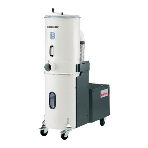
Esta NA-K User manual

OPERATING INSTRUCTIONS
The World of Extraction
NA-K
Stationary Dust Extractors

Your purchase of an ESTA machine has
been a good decision. The design of
our quality products complies with the
latest state of the art. ESTA products
have been devised to provide for clean
air at the workplaces at which they are
applied. This results in an even more
enhanced level of quality and longer
machine times and, particularly, healthier
working conditions. Should you have
any questions pertaining to suction tech-
nology issues, please feel free to contact
us at any time. Our experts will be gladly
at your disposal.
Your ESTA Absaugtechnik Team
The World of Extraction
www.esta.com
Welcome to the sphere of suction
technology

Operating manual
Wet separator
NA-K
Item No. 45.183 (NA-K 1800)
Item No. 45.363 (NA-K 3600)
Item No. 45.603 (NA-K 6000)
Do not use this device unless you have
read the user manual and understand it.
Translation of the original instructions
45603-08-01

2 NA-K 45603-52-01
Edition notice
Original operating manual
Document No.: 45603-08-01
Publishing date: 12.03.2013
Type of device: Wet separator NA-K
Article-No.: 45.183 // 45.363 // 45.603
Publisher
ESTA Apparatebau GmbH & Co. KG Tel.: +49 (0) 73 07 80 4 -0
Gotenstraße 2-6 Fax: +49 (0) 73 07 80 4 -500
Germany Web: www.esta.com
Copyright notice (per DIN ISO 16016:2007-12)
Transfer or reproduction of this document, or the use or communication of its content, is
forbidden without explicit consent. Violators will be liable for damages. All rights to patent, utility
or design registration are reserved.
Warnings and safety instructions
Reference to legal regulations
Note

45603-52-01 NA-K 3
Table of contents
Table of contents 3
1. General safety notes 4
2. Preventing mechanical hazards 4
3. Preventing electrical hazards 4
4. Intended use 5
5. Technical data and description 6
5.1 Technical data (all models) 6
5.2 Functional description 7
6. Delivery and assembly 8
6.1 Connecting processing machines 9
7. Start-up 10
8. Repair and maintenance 12
8.1 Routine tasks 12
8.2 Environmental conditions 13
8.3 Troubleshooting 13
9. Cleaning 14
9.1 Cleaning the wet separator 14
9.2 Cleaning the droplet separator 14
10. Disposal 15
10.1 Disposing of and replacing the contaminated water 15
10.2 Dismantling or disposing of the device 15
11. Device diagram from declaration of conformity 16
12. Declaration of conformity 17
Notes 18
Notes 19
Notes 20

4 NA-K 45603-52-01
1. General safety notes
The device must be used only by persons who have been instructed in its
handling and are explicitly authorized to use it. No aggressive gases may be
exhausted. Make sure that the power cable does not become damaged by being
run over, compressed, pulled, etc. The power cable must be examined regularly
for signs of damage or ageing. When replacing electrical parts and cables, only
original ESTA replacement parts must be used. Work on electrical parts,
including replacement of electrical cables, must be performed only by electrical
experts or people trained for the purpose. When operating a device, use only
original ESTA accessories. Connecting extension cords, coupling devices, etc.,
is not permitted.
Exhausting or dust removal from machines and/or workplaces that
produce aluminium or magnesium dust is not permitted.
According to work equipment user directive 2009/104/EEC, safety devices
for prevention or removal of hazards must be regularly maintained and
inspected by an expert for safe, flawless operation.
2. Preventing mechanical hazards
All movable machine parts driven by electric motors must be covered by securely
fastened protective covers that can be removed only with tools.
If a covering that can only be unfastened with tools is removed, there is risk
of injury if the machine is running.
3. Preventing electrical hazards
All electrical parts must be covered by fixed, securely fastened protective covers
that can be removed only with tools. The device complies with Protection Class I
according to EN 60 204.
Residual risk:
If a covering that can only be unfastened with a tool is removed, a hazard is
posed by electric current.
The power cable (H07RN – F5G2.5... metres long with CEE 32 A plug) must be
replaced only by an authorized electrical specialist.
The power separator (plug) must be activated only when it is shut off.

45603-52-01 NA-K 5
4. Intended use
NA-K series devices are suitable for exhausting dust-producing machines that
give off moist dust or flying sparks. Avoid vacuuming up ignition sources.
In this regard, follow the general safety notes in point 1.
Exhausting or dust removal from machines and/or workplaces that produce
aluminium or magnesium dust and/or combustible or explosive dusts or
combustible gases is not permitted.
Connecting extension cords, coupling devices, etc., is not permitted.

6 NA-K 45603-52-01
5. Technical data and description
5.1 Technical data (all models)
NA-K 1800 NA-K 3600 NA-K 6000
Mode of operation:S1 (continuous
operation)
S1 (continuous
operation)
S1 (continuous
operation)
Type of current: 3N ~ 3N ~ 3N ~
Drive power: kW 3.0 5.5 7.5
Supply voltage: V 400 400 400
Power frequency: Hz 50 50 50
Current consumption: A 6.3 11 14.7
Dimensions: mm
800 x
800 x
2.94
950 x
950 x
3.460
950 x
950 x
3.460
Empty weight approx.: kg 420 500 500
Water capacity approx.: l 290 390 390
Max. volume flow: m³/h 2,100 3,200 5,150
Max. vacuum: Pa 4,200 3,500 3,500
Environmental conditions: °C 5 ≤≤45 °C
Measuring surfaces - sound
pressure level: db (A) 75 79 81
Production year: See model plate

45603-52-01 NA-K 7
5.2 Functional description
This device produces the volume flow and vacuum necessary for suction using a
radial fan that is on top of the housing or next to it.
The dusty air exhausted from the processing machine is guided through a pipeline
or a suitable hose connection to the device’s intake port. The wet separator’s
intake port goes directly into a specially shaped swirl chamber.
The lower portion of the swirl chamber is in water. The exhausted air flows at a
high speed through this chamber and swirls intensely with the water. In this way,
the dust carried in the air is moistened with water and thickens in the water to
become sludge.
A capacitative sensor automatically controls the state of the water and makes sure
that there is always enough water in the device.
There is a droplet separator between the fan and the swirl chamber. The droplet
separator separates the agitated droplets that are still in the air. The water-bound
dust sinks as sludge into the flange-mounted pail.
For easier disposal and maintenance, there are two drain spigots on the sludge
pail.

8 NA-K 45603-52-01
6. Delivery and assembly
The NA-K wet separator is delivered lying on a pallet. After the protective covering
is removed, it can be set up using a crane. The upper part of the NA-K has two
loops for this purpose.
Never use the fan to lift the NA-K!
The wet separator must be set up in such a way that in the front and on the right
side (control module) the device has at least 2 m of free space. The distance from
the ceiling must be at least 50 cm. Further details are in point 8.2 (environmental
conditions) of this operating manual.
After connecting the energy supply, secure the water supply.
Before setting up the cable connection between the device and the power
grid, you must check to make sure the operating voltage shown on the
manufacturer’s plate is the same as that of the grid.
The dust extractor must be set up in such a way that the system’s intake
and discharge openings are secure against foreign objects falling in or
being sucked in. The device must be placed on a level surface with a load
capacity of at least 1,000 kg. To improve stability, bolt the device to the
floor.
Dust extractors and collection containers must never be set in direct
sunlight.
There should be an open distance of 2 metres around the device to provide
enough room for maintenance.
The maintenance doors must be freely accessible. The dust extractor must
be set up to allow easy inspection and cleaning (such as removing dust
build-up on the fan wheel).
When operating the device, the legal requirements of the clean air act and
the immission control act.
Disposal of packaging: The wet separator is delivered on a EURO wooden pallet
and is protected from dirt by a PE film.
Both materials must be disposed of or recycled according to local regulations.

45603-52-01 NA-K 9
6.1 Connecting processing machines
To correctly exhaust a dust-producing machine, the pipe or hose connection and
the electrical connection must be created between the processing machine to be
exhausted and the NA-K.
The diameters of the hoses and pipes must be chosen so as to ensure a
minimum interior air speed of 20 m/s.
If several processing machines are connected to the NA-K, the total volume flow
is divided among the individual devices. Find out the volume flow necessary for
exhaust from the machine’s manufacturer.
The data shown in the chart can be taken as reference values:
Pipe or hose diameter Airflow volume at
20 m/s
50 mm 141 m³/h
70 mm 277 m³/h
80 mm 362 m³/h
100 mm 566 m³/h
125 mm 884 m³/h
140 mm 1,108 m³/h
160 mm 1,448 m³/h
180 mm 1,832 m³/h
200 mm 2,262 m³/h
225 mm 2,863 m³/h
250 mm 3,534 m³/h
280 mm 4,434 m³/h
300 mm 5,090 m³/h

10 NA-K 45603-52-01
7. Start-up
Check the fan’s direction of rotation as it operates.
Before starting a device with three-phase drive, please make sure that the drive
motor’s direction of rotation is correct.
Proceed as described below:
1. The device must be ready to operate (enough water, main switch at the “I”
position).
2. Turn on the fan.
3. Wait 5 seconds.
4. Turn off the fan.
5. Check to see that the motor fan wheel is moving in the direction of the
arrow.
When the direction of rotation is wrong, the device gets impermissibly hot,
and performance suffers.
For devices that are delivered ready to connect with CEE plugs, the rotating field
can be changed using the rotating pole pins in the phase inverter. Use an
appropriate screwdriver to press lightly while turning the pole pins and change
their sequence.
For devices that are connected to the electrical grid without plug
connections, the phase swap must be performed by a trained electrical
specialist.
Before start-up, all of the dust extractor’s maintenance openings must be
closed. Sudden closing of the suction port during operation must always be
avoided.
To start up the NA-K, the red-yellow main switch on must first be turned to position
“I”. For devices with a control cabinet: The red and green button for turning the fan
wheel on and off is on the front of the switch box. The green signal light goes on
when the fan motor is running.
If the level control’s signal light goes on, the device’s water level is too low
and no suction can occur.

45603-52-01 NA-K 11
The water level control is active as soon as the main switch is activated. Because
the water pressure at the NA-K’s inlet valve can vary from place to place, the time
necessary for water filling also varies. Therefore the device’s controls must be
adapted to the water supply network at the place where it is set up. For this
purpose, the time between the response of the capacitative sensor and the
attainment of target water level is stopped. The target water level is about 2 cm
above the minimum mark. The sensor’s response can be seen on the level control
(the red light goes out). The stop time is set at the K2T time relay.
The operator of the NA-K must see to it that, if the device is defective, the
escaping water causes no damage to persons, machines, fixtures, buildings
or the environment!
One possible way of preventing damage from escaping water is setting the
device up in a water-tight catch basin with an automatic simultaneous alarm
sent to an appropriate person (maintenance person, gatekeeper, etc.).

12 NA-K 45603-52-01
8. Repair and maintenance
8.1 Routine tasks
Check daily:
Is there damage to the device or its parts?
Is there mechanical damage to the power cable?
Is the fill level sensor’s measurement impaired by dirt on the
inspection window?
Check monthly:
Is the seal between the sludge pail and the device housing
perfect?
Does the water fill level control work properly? Drain the
water while the fan is running. If the water goes below the
minimum mark on the inspection glass, open the water
intake valve.
Is the swirl chamber or gas deflector damaged (by
corrosion) or is its diameter changed by build-up?
Is the droplet separator contaminated?
Is there corrosion anywhere inside the device?
If heavily soiled, the device interior must be cleaned.
A log is to be kept of the monthly inspection. It must document the date of
inspection, deficiencies determined and the name of the inspector.
When necessary, of course, the device must be repaired.

45603-52-01 NA-K 13
8.2 Environmental conditions
Ambient temperature:
5 ≤≤45 °C
Air humidity:
Max. 80%
Before a long downtime, make sure that the wet separator is cleaned.
8.3 Troubleshooting
In an emergency (fire, etc.), the device must be turned off at the emergency shut-
off switch.
During repairs to the device, make absolutely sure that the red-yellow main
switch is turned to the “0” position and is secured with a padlock against
unintentional reactivation.
The following chart describes possible malfunctions that may arise during
operation of NA-K models, their cause and possible solutions.
Problem Cause Solution
The level control’s main
signal light stays on.
The water is too low.
See if the water intake is
correct, and if necessary
turn the spigot further.

14 NA-K 45603-52-01
9. Cleaning
9.1 Cleaning the wet separator
The device must be cleaned at regular intervals — at least once a month.
Water is the recommended cleaning agent.
For correct operation of the device, clean surroundings are necessary. Therefore
make sure that dust build-up is removed from the surface of the dust extractor.
9.2 Cleaning the droplet separator
The NA-K is equipped with a droplet separator. Its purpose is to separate the
droplets still remaining in the cleaned air, before they leave the device. After
extended use, dirt settles in the droplet separator’s channels. This causes higher
internal air resistance in the device, reducing suction performance.
If this occurs, the droplet separator must be thoroughly cleaned.
The droplet separator must be cleaned or maintained as follows:
1. Open the upper doors on the wet separator by turning the star grip clockwise.
2. Pull the droplet separator out using the front grips.
3. Now the droplet separator can be properly cleaned (with a steam jet).
4. Slide the cleaned droplet separator back into the device.
5. Close the doors and lock them by turning the star grip. The NA-K is ready to
work.

45603-52-01 NA-K 15
10.Disposal
10.1 Disposing of and replacing the contaminated water
With time, the water in the NA-K gets used up and must be completely changed.
For this, two drain spigots are mounted on the device. Drain the lightly
contaminated water in the upper part of the NA-K through the upper spigot, and
the rest of the water with the lower spigot mounted on the sludge pail. For better
cleaning, use the four quick-tension locks to disconnect the sludge pail from the
device. It is best to clean the device thoroughly before filling it with fresh water.
This increases the useful life of the water. Before refilling with water, the sludge
pail must be reconnected to the device, and the drain spigots must be closed.
Dispose of the contaminated water and the sludge build-up in an
environmentally sound manner, according to local regulations.
With some dusts, the water tends to foam.
In that case, an anti-foaming agent (such as soda) should be added to the
water.
10.2 Dismantling or disposing of the device
Instructions on dismantling, packaging and loading
Before any necessary dismantling, the electricity and water must be disconnected
and the water and sludge should be drained. Do this as in the cleaning procedures
described in 8.4 and 8.5.
To transport the device, use the loops at the top of the NA-K to set it on a pallet,
and cover it with film against dirt.
Never use the fan to lift the NA-K!
Disposing of or returning the device
After removal of the water and sludge, and after all connections have been
removed, the device can undergo the standard disposal process. Explicitly comply
with regulations.
The device cannot be returned to ESTA.

16 NA-K 45603-52-01
11.Device diagram from declaration of conformity
1. Motor
2. Exhaust release
3. Fan
4. Gas deflector
5. Droplet separator
6. Raw gas intake port
7. Swirl chamber
8. Water
9. Device cone
10.Sludge pail
11.Drain spigots

45603-52-01 NA-K 17
12.Declaration of conformity
EC Conformity declaration for machines
Name of manufacturer: ESTA APPARATEBAU GmbH & Co. KG
Address of manufacturer: Gotenstraße 2 – 6,
89250 Senden
Person in charge of Ramona Pflum
documentation: Gotenstr. 2 - 6
89250 Senden
We hereby declare that the design of the machine
Machine: Dust extractor for exhausting dust
Series: NA-K
Model: NA-K 1800, NA-K 3600, NA-K 6000
conforms to the applicable directives:
2006/42/EG - EG Machine directive,
2004/108/EC Directive on Electromagnetic Compatibility
Reconciled norms used:
EN 12100 Safety of machinery - basic concepts,
general propositions (part 1 and part 2)
EN 13857 Safety of machinery, devices and systems;
safety distances for avoiding
hazard zones
EN 349 Safety of machinery; minimum distances for preventing
body parts from being crushed
EN 60 204-1 Machine safety - Electrical
machinery equipment,
EN 61 000-6-3 Electromagnetic compatibility
Emitted interference in domestic applications.
Senden, 03.05.2012 Dr. Peter Kulitz
CEO

18 NA-K 45603-52-01
Notes
ESTA Apparatebau GmbH & Co. KG
Gotenstraße 2 - 6
89250 Senden / Ay
Tel.: +49 (0) 7307 804 - 0
Fax: +49 (0) 7307 804 - 500
www.esta.com
Table of contents
Other Esta Vacuum Cleaner manuals
Esta
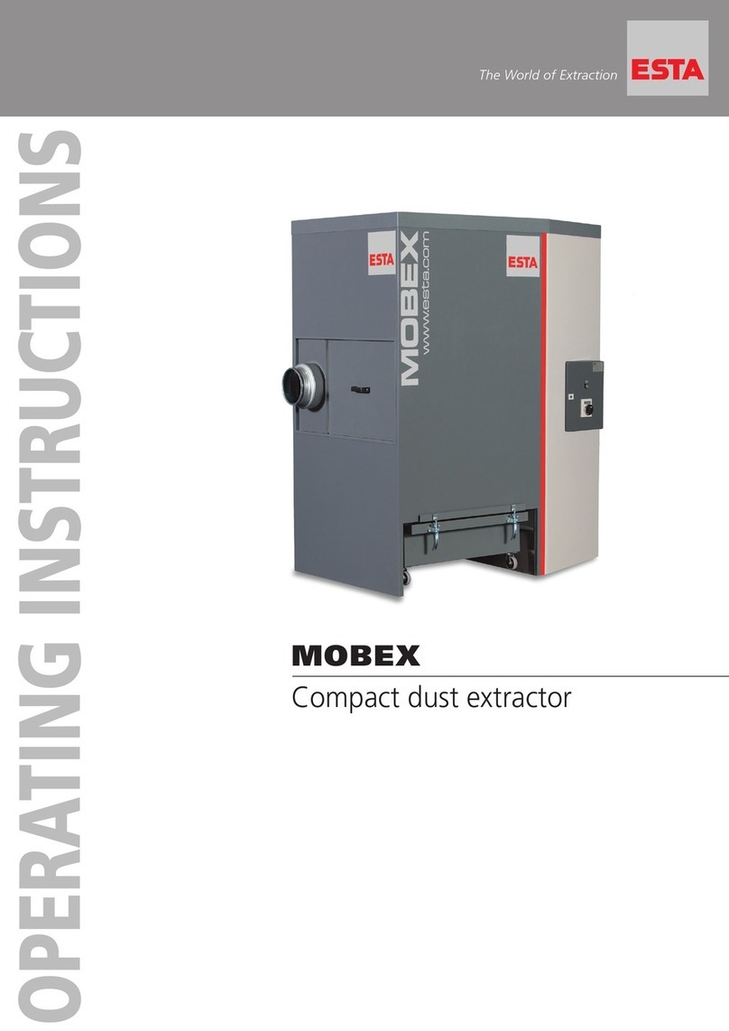
Esta MOBEX P-24 User manual
Esta
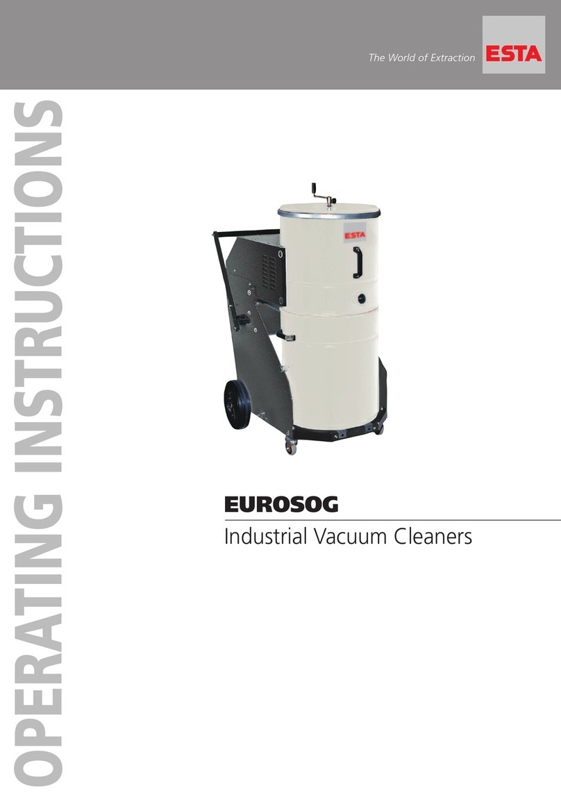
Esta EUROSOG-W/N User manual

Esta
Esta DDE 1500 User manual
Esta
Esta NA-K B/VA User manual
Esta
Esta EUROSOG - ATEX User manual

Esta
Esta DUSTOMAT-160 S User manual
Esta
Esta DUSTOMAT 4 ATEX User manual
Esta
Esta DUSTOMAT-21 User manual

Esta
Esta DUSTOVAC 5.5 FM User manual
Esta
Esta WHISPERSOG User manual
