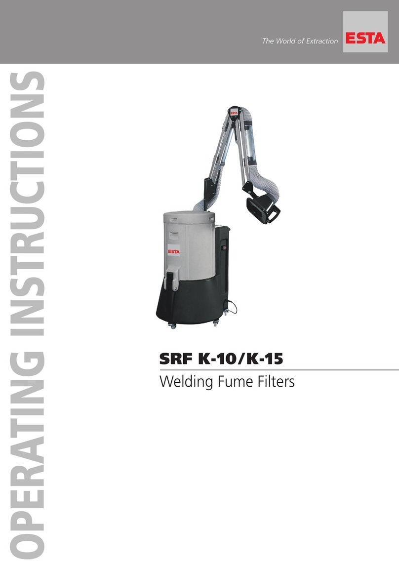
Esta SRF T-2 User manual

The World of Extraction
OPERATING INSTRUCTIONS
SRF T-2/T-4
Welding Fume Filter
C
E
R
T
I
F
I
E
D
I
S
O
9
0
0
0
:
2
0
0
8
QUALITY

Your purchase of an ESTA machine has
been a good decision. The design of
our quality products complies with the
latest state of the art. ESTA products
have been devised to provide for clean
air at the workplaces at which they are
applied. This results in an even more
enhanced level of quality and longer
machine times and, particularly, healthier
working conditions. Should you have
any questions pertaining to suction tech-
nology issues, please feel free to contact
us at any time. Our experts will be gladly
at your disposal.
Your ESTA Absaugtechnik Team
The World of Extraction
www.esta.com
Welcome to the sphere of suction
technology

Operating Instructions
SRF T-2
SRF T-4
Item no. 55.101 (SRF T-2)
Item no. 55.102 (SRF T-4)
Do not use this device unless you have
read the operating instructions and understood them.
Original operating instructions
55101-08-01

2
SRF T-2; T-4
55101-52-01
Edition notice
Original operating instructions
Document no.: 55101-08-01
Publishing date: 16/06/2016
Type of device: SRF T welding fume filter
Article no.: 55.101 // 55.102 and variants
Publisher
ESTA Apparatebau GmbH & Co. KG Tel.: +49 (0) 73 07 80 4 -0
Gotenstr. 2-6 Fax: +49 (0) 73 07 80 4 -500
Germany www.esta.com
Copyright notice (per DIN ISO 16016:2007-12)
Transfer or reproduction of this document, or the use or communication of its content, is forbidden
without explicit consent. Violators will be liable for damages. All rights to patent, utility or design
registration are reserved.
Warning and safety information
Danger from electrical current
Note
Reference to ESTA customer service
Reference to legal regulations

55101-52-01
SRF T-2; T-4
3
Contents
Contents .....................................................................................................................................3
1. General notes on safety ......................................................................................................4
2. Preventing mechanical hazards .........................................................................................6
3. Preventing electrical hazards .............................................................................................6
4. Preventing dust hazards .....................................................................................................6
5. Intended use ........................................................................................................................7
6. Technical data and description ..........................................................................................8
6.1 Welding fume filter..............................................................................................................8
Technical changes reserved.....................................................................................................8
6.2 Function description ...........................................................................................................8
7. Delivery, assembly and commissioning............................................................................9
7.1 Delivery and transport ........................................................................................................9
7.2 Assembly............................................................................................................................9
7.3 Commissioning...................................................................................................................9
8. Maintenance and troubleshooting ...................................................................................10
8.1 Maintenance instructions.................................................................................................. 10
8.2 Inspection and maintenance intervals...........................................................................11
8.3 Troubleshooting................................................................................................................12
9. Monitoring the minimum air volume flow........................................................................ 13
10. Cleaning ............................................................................................................................. 13
10.1 Rotary cleaning system ..................................................................................................14
10.2 Changing the filter ..........................................................................................................14
...............................................................................................................................15
11. Disposal..............................................................................................................................15
11.1 Disposal of the collected dust.........................................................................................15
11.2 Disposal of the device ...................................................................................................15
12. Device image...................................................................................................................... 16
13. Declaration of Conformity.................................................................................................17
Notes.........................................................................................................................................18
Notes.........................................................................................................................................19
Notes.........................................................................................................................................20

4
SRF T-2; T-4
55101-52-01
1. General notes on safety
Before operation, all persons who are to use the device or perform maintenance
on it must be provided with information, instructions and training in using the device
and on the substances for which it is to be used, including the procedure for safe
disposal of the collected material. Responsibilities must be clearly established for
the following:
Installation
Commissioning
Operation
Maintenance and repairs
The device must be used only by persons who have been instructed in its handling
and are explicitly authorised to use it.
Always keep the operating instructions in the place where the device is being used,
so that they can be viewed by personnel at all times.
The device must be used exclusively for the extraction of welding fumes. The
device may not be used to extract liquids, aggressive gases easily-flammable
media or glowing particles (hotspots or similar) under any circumstances.
The use of the device while welding oiled metal parts is not permitted. Fire hazard!
The device may not be used or stored outside in wet conditions.
Only original ESTA spare parts may be used; otherwise your warranty is voided.
During extraction, the volume flow returned from the device to the room must be
no more than 50% of the supply air. With open room ventilation, supply air flow
should be assumed as equal to the room volume every hour. This means that the
rate of air replacement must be once per hour.
Supply air flow [m³/h] = room volume [m³] air replacement rate [1/h]
Example:
When the device is operating at the nominal airflow volume of 200 m³/h, the same
volume of fresh air must be fed in. This occurs with natural ventilation if the volume
of the work room is 2000 m³ (e.g., 58 m² surface with a 3.5 m ceiling height).
When using the extraction element of the extraction arm, take into account the
suction distance of approx. 200 mm and position the arm based on the thermally
induced motion of the welding smoke.

55101-52-01
SRF T-2; T-4
5
You must ensure that the power cable does not become damaged from being run
over, crushed, strained or suchlike.
The power cable should be checked regularly for signs of damage or ageing.
The device must not be used if damage is detected to the power cable.
Replacing the power cable and the power plug may only be performed by an
electrical specialist or a person trained for this purpose.
The spare parts of the mains or device connection cables required for this must
only be used with original parts specified by ESTA. This will ensure that these
components are splash-proof and possess the necessary mechanical strength
required by the applicable standards.
The power plug may only be plugged in once the welding fume filter has been set
up in its installation location. This requires a 16-A Schuko wall socket with a slow-
blow fuse (VDE-approved).
All plugs and connectors used for the connection of electrically driven industrial
dust extractors and standard dust extractors must comply with EN 61241-14.
Coupling connector devices and adapters are not permitted.
After use, before moving the device to another site and before cleaning,
maintenance, or replacement, or removal of movable parts, the device must be
unplugged and, if present, the compressed air supply disconnected.
Use only original ESTA accessories to operate the dust extractor.
The device contains toxic dust after the first time it is used. Emptying and
maintenance procedures must be performed by expert personnel who are
wearing appropriate personal protective equipment. The device may not be
operated without the complete filtration system!
The directives 89/655/EEC and TRGS 560 require that safety devices for the
prevention or remedy of hazards be subject to regular maintenance and
inspection by a trained person for their fault-free function.

6
SRF T-2; T-4
55101-52-01
In all emergencies, the device must be disconnected from the power supply
immediately, turned off at the emergency stop switch and the plug pulled
immediately. If there is a fire, the fire department is to be alerted immediately,
and the fire must be contained by appropriate means.
2. Preventing mechanical hazards
All movable machine parts driven by electric motors must be covered by fixed,
securely fastened protective covers that can be removed only with tools.
Residual risk:
If a covering that can only be unfastened with tools is removed, a risk of
injury cannot be ruled out when the machine is running.
3. Preventing electrical hazards
All electrical parts must be covered by fixed, securely fastened protective covers
that can be removed only with tools. The device complies with Protection Class I
according to EN 60 335.
Residual risk:
If a covering that can only be unfastened with tools is removed, the risk of
electric shock cannot be ruled out.
4. Preventing dust hazards
When emptying the dust collection container, it is possible to inhale dust. This risk
can be minimised by complying with the specifications outlined in section "Disposal
of the collected dust".
When transporting the device, all suction openings must be closed to prevent dust
from escaping.

55101-52-01
SRF T-2; T-4
7
5. Intended use
The ESTA welding fume filter has been manufactured according to the latest
technology and all recognized safety regulations.
The SRF T-2 or T-4 welding fume filter is suitable for the extraction of welding
fumes when welding unalloyed or low-alloyed steels at individual portable welding
stations. Cleaned air can be returned in the work room. The devices is equipped
with dust class “M” (moderate hazard) filters for the separation of dust and fumes
with an exposure limit of more than 0.1 mg/m³.
A special version of the device allows the use of a soldering fume filter.
Not suitable for the extraction of welding fumes during the welding of oil-
covered parts.
The device may not be used or stored in wet conditions.
The devise is designed for commercial use, such as in industrial enterprises and
workshops.
Other applications are considered unintended use. ESTA is not liable for damages
due to unintended use.
The dust extractor has been constructed by ESTA in accordance with the
operator’s specifications.
When connecting a suction hose, make sure that only electrically conductive hoses
are used and that the electrical connection between the hose and the port is fault-
free. If a so-called “spiral hose” is used, the metal spirals must be stripped and
pressed to the bare wall of the extraction port with a pipe clamp after the hose is
attached.
All plugs and connectors used for the connection of electrically driven
industrial dust extractors and standard dust extractors must comply with EN
61241-14. Extension cables, coupling connector devices and adapters are
not permitted.

8
SRF T-2; T-4
55101-52-01
6. Technical data and description
6.1 Welding fume filter
Technical changes reserved
Model:
(see model plate)
T-2
T-4
Max. airflow volume
[m³/h]
200
400
Connection diameter
[mm]
50
2 x 50
Max. vacuum
[Pa]
19,000
19,000
Connection voltage
[V]
230
230
Drive power
[kW]
1.1
2.2
Nominal frequency
[Hz]
50
50
Filter area
[m²]
0.8
1.6
Dimensions (L x W x H)
[mm]
390 x 210 x 500
490 x 400 x 560
Max. sound pressure
level
[dB(A)]
66
66
Weight
[kg]
15
27
Production year
See model plate
6.2 Function description
The welding fume filter is equipped with either a 1.1 kW (T-2) or 2 x 1.1 kW (T-4)
turbine suction unit, depending on the model. The device is switched on and off
via a green rocker switch.
The vacuum created by the turbine sucks in air via the suction hose that is
connected to the intake port.
A specially designed permanent filter located in the filter housing separates the
dust from the extracted air.
The purified air is returned to the room through an exhaust slot.
The minimum volume flow is indicated by the red dot on the integrated manometer.
If the minimum volume flow is not reached, the filter must be cleaned using
compressed air.
By cleaning the filter elements, fume residue is removed and the filter elements
are regenerated. The tray at the bottom collects the extracted dust. The tray must
be checked after each use.

55101-52-01
SRF T-2; T-4
9
7. Delivery, assembly and commissioning
7.1 Delivery and transport
The welding fume extractor is delivered in a cardboard packaging. The device is
ready to plug in and use immediately on delivery.
Please inspect the device for transportation damage when it arrives.
Any identifiable damage must be reported and documented immediately.
ESTA Customer Service: +49 (0) 7307 804 - 0
When setting up the device, ensure that the floor has sufficient load-bearing
capacity.
7.2 Assembly
No additional assembly work is required, other than connecting the device to the
power supply, the suction hose and the compressed air supply when cleaning the
device after use.
7.3 Commissioning
Only persons authorised in accordance with section “General notes on
safety” may commission the device.
Before establishing cable connections between the device and the mains,
check that the operating voltage specified on the factory plate matches that
of the mains supply.
Set up the device on an even surface as close as possible to the workstation.
The wheels on T-4 type devices must be locked.
Before the device is first used, a function check must be performed.
The on/off switch is used to switch the device on and off.

10
SRF T-2; T-4
55101-52-01
8. Maintenance and troubleshooting
8.1 Maintenance instructions
For maintenance by qualified personnel, the device must be opened, cleaned, and
inspected at the given locations, as far as this is feasible, without any hazard being
posed to maintenance personnel or to other persons. Appropriate precautionary
measures are to be taken prior to the cleaning and removal of wear parts. This
includes locally filtered forced-air ventilation in the area in which the device is being
maintained and proper personal protective gear.
During maintenance or repair work, all soiled objects that can no longer be
adequately cleaned must be disposed of. Such objects must be discarded in
impermeable bags in compliance with applicable regulations for disposal of such
refuse.
If the device is not needed in its location of use for a long time, it must be stored in
a dry room. The temperature should not be below 5°C or above 25 °C.
Before storing the device, we recommend that you wipe it clean with a damp cloth;
clean the filter; and empty the dust container.
Under no circumstances may the device be cleaned by being sprayed down with
jets of water.
The operator is obligated to have maintenance performed once per year.
During this process, the correct function of the device must be checked by
a trained specialist. Records must be kept of the main annual inspection in
the maintenance book provided. The date of the inspection, detected
deficiencies and the name of the auditor must be visible from this. The date
of the next maintenance session can be read on the inspection plate
installed on the device.

55101-52-01
SRF T-2; T-4
11
8.2 Inspection and maintenance intervals
Regular maintenance consists of 3 intervals:
1. Daily inspection includes:
By the device user
Visual inspection
For damage to the device or its parts,
For mechanical damage to the power cable
For a full dust collection container (regulations require that the container be
emptied if it is more than 2/3 full),
2. Monthly inspection includes:
By expert maintenance personnel
Visual and function check
for filter leaks (dust trails or deposits on the air outlets)
to ensure the minimum airflow volume control is working To carry out the
check, the air inlet of the device must be closed, and the manometer needle
should move past the red dot.
3. The main annual inspection includes:
The last test by ESTA is documented on the device.
In collaboration with the ESTA maintenance service
Flow volume measurement
Low-pressure measurement
Power consumption measurement
Visual check of filters
Seal inspection
After maintenance, the device receives a new test plate to document that
maintenance has been performed.
This inspection must be performed once annually!
Written records of servicing work are to be kept in the maintenance book
provided. This must make clear the equipment inspected and, if necessary,
the deficiencies found, along with the name of the inspector and the date of
the inspection.
Switch off the dust extractor immediately following a malfunction and notify
the responsible maintenance service.
Maintenance work must be performed according to accident prevention
regulations. The device must be disconnected from the mains and
compressed air supply.

12
SRF T-2; T-4
55101-52-01
According to work equipment user directives 89/655/EEC and TRGS 560,
safety devices for the prevention or removal of hazards must be regularly
maintained and inspected by an expert for safe, flawless operation.
Get the most from ESTA’s maintenance service!
A maintenance contract ensures a long life span and smooth operation for
your dust extractor.
We’ll make you a great offer — just call us up:
ESTA Maintenance Service: +49 (0) 7307 804 - 0
ESTA Spare Parts Service: +49 (0) 7307 804 - 0
8.3 Troubleshooting
If a fault is detected, always use the following check list. Immediately call the ESTA
maintenance service if a fault emerges which is not covered in this list. Do not
perform any repair work on the device yourself which is explicitly permitted.
Fault
Possible cause
Possible solution
Suction too weak,
manometer needle on red
dot.
Main filter is dirty.
Clean filter.
Suction hose is blocked.
In a vacuumed room,
hold the hose vertically
and knock out with a
rubber mallet.
Manometer needle stays
on or past the red dot
despite cleaning the filter.
Filter pores are blocked.
Perform filter change.
Should dust escape or cloud up from the air outlet openings; given the
development of smoke; or should the ventilator run loudly; disconnect the
device from the power supply immediately.

55101-52-01
SRF T-2; T-4
13
9. Monitoring the minimum air volume flow
A safety device is built into the device for monitoring the
minimum air flow volume to be extracted. The air flow volume is
monitored using a manometer. A red dot is positioned on the
scale to indicate the minimum volume flow limit. If the
manometer shows excessive negative pressure, the filter must
be cleaned.
10.Cleaning
The people assigned to cleaning work must be instructed on the aspirated
toxic materials and wear a breathing protection mask with a class P3 particle
filter, as well as protective gloves. Harm to bystanders must be prevented
by all means.
During cleaning work, all soiled objects that can no longer be adequately
cleaned must be disposed of. Such objects must be discarded in
impermeable dust bags in compliance with the applicable regulations for
disposal of such refuse.

14
SRF T-2; T-4
55101-52-01
10.1 Rotary cleaning system
Minimum air pressure: 4.5 bar
Maximum air pressure: 6 bar
If the manometer needle of the device has moved past the
red dot during operation (meaning the minimum volume
low is not reached), the filter must be cleaned.
This procedure should be carried out during downtimes.
The following steps must be carried out in the described
order:
After the device has shut down, wait approx. one minute
for the dust in the device to settle.
Then connect a compressed air hose with a DN-type 7.2
¼-inch coupling to the ¼-inch nipple on the rotary cleaning unit. After opening the
valve lever, the compressed air causes the cleaning nozzle to rotate inside the fine
filter cartridge. By moving the tube up and down, fume residue is removed and the
filter is regenerated from top to bottom.
The tray at the bottom collects the extracted dust. The tray must be emptied after
each cleaning. To empty the tray, unscrew the knurled nuts and remove the tray.
If the suction power does not improve after cleaning, the filter must be replaced.
10.2 Changing the filter
The replacement of the filters must be performed in a well-ventilated room
or outdoors. The people assigned to this work must be instructed on the
extracted toxic materials and wear a breathing protection mask with a class
P3 particle filter, as well as protective gloves. Harm to bystanders must be
prevented by all means.
After an extended period of operation, the filters clog up slowly due to the ingress
of extremely fine dust in the pores. Even a cleaning device can no longer remove
this infiltrated dust. The filter must be replaced with a new one.
If possible, the filter must be replaced when there is no other work going on. The
old filter must be disposed of according to local regulations.

55101-52-01
SRF T-2; T-4
15
Before replacing the filter, any loose dust must first be removed using the
accompanying cleaning system, and the device disconnected from the
mains.
Unscrew the four cross-head screws from the cover of the device, and lift up the
entire part by the handle.
Now unscrew the two safety nuts from the threaded rod of the filter in question and
remove the U-profile.
The filter can now be removed.
The new filter is installed using the same procedure in reverse order.
Do not clean the removed filter mat by beating or blowing on it.
11.Disposal
Persons assigned to disposal work must be instructed on the extracted toxic
materials and wear a breathing protection mask with a class P3 particle filter,
as well as protective clothing. Harm to bystanders must be prevented by all
means.
11.1 Disposal of the collected dust
To dispose of the collected dust, the dust collection tray must be removed by
unscrewing the two knurled nuts. The dust collection tray can now be removed.
The dust in the tray must be disposed of according to the local regulations.
11.2 Disposal of the device
To dispose of the device, first empty the dust collection tray and remove the filter
cartridges, then dispose of these according to local regulations.
The device must be packaged in an appropriate manner and disposed of according
to local regulations.
Due to contamination of the device with dust hazardous to health, it cannot be
returned to ESTA.

16
SRF T-2; T-4
55101-52-01
12.Device image
With reference to the model information, please request the replacement
parts you need from the ESTA Spare Part Service: +49 (0) 7307 804 - 0
SRF T-2 / SRF T-4 welding fume filter
Dust collection drawer
Knurled nut
Suction openings
Connection for
suction hose
On/off switch and
manometer for the
monitoring of minimum
volume flow
Cover, unscrews to replace
filter
Compressed air
connection for the rotary
cleaning system
SRF T-2
SRF T-4

55101-52-01
SRF T-2; T-4
17
13.Declaration of Conformity
Name of manufacturer: ESTA Apparatebau GmbH & Co. KG
Address of manufacturer: Gotenstraße 2 - 6
89250 Senden
Name of the authorised
document representative: ESTA Apparatebau GmbH & Co. KG
Gotenstraße 2 - 6
89250 Senden
We hereby declare that the design of the machine
Machine: Dust extractor for the collection, transport and separation of dry
dust and welding fumes
Series: SRF T welding fume filter
Model: SRF T-2, …T-4
was developed, designed and produced in accordance with the requirements of directive
2006/42/EG. The protective aims of the 2014/35/EU Low Voltage Directive have been
accomplished in accordance with Appendix I, No. 1.5.1 of the 2006/42/EC Machinery
Directive.
The device also fulfils the protection requirements of the following EU directives:
2014/30/EU EU Electromagnetic Compatibility Directive
Reconciled norms used:
DIN EN 12100 Safety of machinery –Basic concepts, general principles for design
DIN EN 13857 Safety of machinery, devices and systems; safety distances to prevent
hazard zones from being reached
DIN EN 349 Safety of machinery; minimum distances for preventing body parts from
being crushed
DIN EN 60335 Safety of electrical devices for household use and similar
(Part 1 and part 2-69)
EN 61000-6-3 Electromagnetic compatibility –Interference for residential, commercial
and light-industrial environments
EN 61000-6-4 Electromagnetic compatibility –Interference for industrial environments
EN 61000-3-11 Electromagnetic compatibility –Limits –Limitation of voltage changes
National norms and technical specifications used:
VDI 3677 Filtering separators
Senden, 16/06/2016 Dr. Peter Kulitz
Managing Director
This manual suits for next models
1
Table of contents
Other Esta Water Filtration System manuals