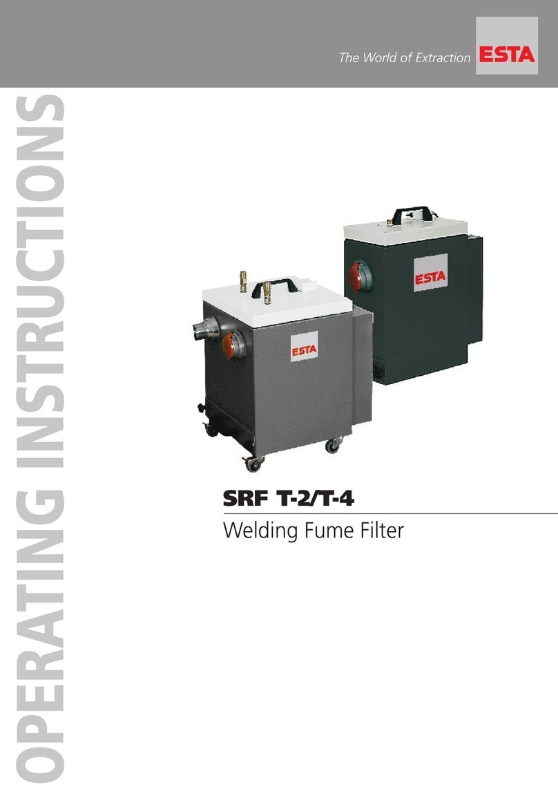
Esta SRF K-10 User manual

OPERATING INSTRUCTIONS
The World of Extraction
SRF K-10 / K-15
Welding Fume Filters

Your purchase of an ESTA machine has
been a good decision. The design of
our quality products complies with the
latest state of the art. ESTA products
have been devised to provide for clean
air at the workplaces at which they are
applied. This results in an even more
enhanced level of quality and longer
machine times and, particularly, healthier
working conditions. Should you have
any questions pertaining to suction tech-
nology issues, please feel free to contact
us at any time. Our experts will be gladly
at your disposal.
Your ESTA Absaugtechnik Team
The World of Extraction
www.esta.com
Welcome to the sphere of suction
technology

Operating manual
SRF K-10 FM
SRF K-15 FM
Item No. 55.203 (SRF K-10 FM)
Item No. 55.235 (SRF K-10 FM IFA W3)
Item No. 55.235.005 (SRF K-10 FM IFA W3)
Item No. 55.212 (SRF K-15 FM)
Item No. 55.229 (SRF K-15 FM IFA W3)
Item No. 55.229.003 (SRF K-15 FM IFA W3)
Do not use this device unless you have
read the user manual and understand it.
Translation of the original instructions
55203-08-02

2 SRF K-10 & K-15 55203-52-02
Edition notice
Original operating manual
Document No.: 55203-08-02
Publishing date: 30.04.2015
Type of device: SRF K welding fume filter
Item No.: 55.203 // 55.234 // 55.234.005 // 55.235 // 55.235.005 // 55.212 // 55.228 //
55.228.007 // 55.229 // 55.229.003 and variations
Publisher
ESTA Apparatebau GmbH & Co. KG Tel.: +49 (0) 73 07 80 4 -0
Gotenstraße 2-6 Fax: +49 (0) 73 07 80 4 -500
Germany www.esta.com
Copyright notice (per DIN ISO 16016:2007-12)
Transfer or reproduction of this document, or the use or communication of its content, is
forbidden without explicit consent. Violators will be liable for damages. All rights to patent, utility
or design registration are reserved.
Warnings and safety instructions
Electrical current hazard
Note
Reference to ESTA customer service
Reference to legal regulations

55203-52-02 SRF K-10 & K-15 3
Contents
Contents .....................................................................................................................................3
1.General safety notes ...........................................................................................................4
2.Preventing mechanical hazards.........................................................................................6
3.Preventing electrical hazards.............................................................................................6
4.Preventing dust hazards.....................................................................................................6
5.Intended use ........................................................................................................................7
6.Technical data and description..........................................................................................8
6.1 Welding fume filter..............................................................................................................8
6.2 Functional description.........................................................................................................9
7.Delivery, installation and start-up....................................................................................10
7.1 Delivery and transport ......................................................................................................10
7.2 Installation ........................................................................................................................10
7.3 Start-up.............................................................................................................................12
8.Maintenance and troubleshooting ...................................................................................13
8.1 Maintenance instructions..................................................................................................13
8.2 Inspection and maintenance intervals ..............................................................................14
8.3 Troubleshooting................................................................................................................16
9.Monitoring the minimum airflow volume.........................................................................17
10.Cleaning .............................................................................................................................18
10.1 Cleaning the filter manually (standard version) ..............................................................18
10.2 Rotation cleaning (supplementary equipment) ...............................................................19
10.3 Automatic cleaning (supplementary equipment)............................................................. 19
10.4 Filter replacement...........................................................................................................20
11.Disposal..............................................................................................................................21
11.1 Disposing of collected dust materials .............................................................................21
11.2 Disposing of the device ..................................................................................................22
12.Optional equipment...........................................................................................................23
12.1 Start-up with potential-free contact ................................................................................. 23
12.2 Additional lighting ...........................................................................................................23
12.3 Wall console ...................................................................................................................24
12.4 Using an activated carbon filter ......................................................................................24
12.5 Discharge air port ...........................................................................................................24
13.Device diagram..................................................................................................................25
14.Declaration of conformity .................................................................................................26
Notes.........................................................................................................................................27
Notes.........................................................................................................................................28

4 SRF K-10 & K-15 55203-52-02
1. General safety notes
Before operation, all persons who are to use the device or perform maintenance
on it must be provided with information, instructions and training in using the
device and on the substances for which it is to be used, including the procedure
for safe disposal of the collected material. Responsibilities must be clearly
established for the following:
Installation
Start-up
Operation
Maintenance and repair
The device must be used only by persons who have been instructed in its
handling and are explicitly authorized to use it.
Always keep the operating manual at the place where the device is being used, so
that it can be seen by personnel at all times.
The device must be used only to exhaust welding fumes. No liquids, aggressive
gases, easily flammable materials or glowing particles (such as hot embers) may
be aspirated.
Use of the device when welding oil-covered metals is prohibited. Fire hazard!
The device must not be used or stored outdoors or under wet conditions.
Only original ESTA replacement parts must be used; use of other products will
void the warranty.
During exhaust, the volume flow returned from the device into the room must be
no more than 50% of incoming air. With free room ventilation, the incoming airflow
must equal the room volume every hour. This means that the rate of air
replacement must be once per hour.
Incoming airflow [m³/h] = room volume [m³] air replacement rate [1/h]
Example:
When the device is operating at the nominal airflow volume of 2,000 m³/h the
same volume of fresh air must be fed. This occurs with natural ventilation if the
volume of the workroom is 2,000 m³ (e.g., 835 m² surface with a 2.4 m ceiling
height).
The exhaust arm’s detection device must be tracked in consideration of the
suction range of about 200 mm and of exploitation of the welding site’s welding
fume movement.

55203-52-02 SRF K-10 & K-15 5
Make sure that the power cable does not become damaged by being run over,
compressed, pulled, etc.
The power cable must be examined regularly for signs of damage or ageing.
The device must not be used if damage to the power cable is determined.
The power cable and plug must be replaced only by an appropriately trained
electrical specialist.
For the power supply and the device’s power cords, only original ESTA
replacement parts must be used. This guarantees that they are spray-proof
according to applicable standards and have the necessary mechanical strength.
The power cord must be plugged in only after the welding fume filter has been
successfully set up at its place of use. On devices with alternating current drive
(SRF K-10) a 16 amp protected wall socket, and for devices with three-phase
drive (SRF K-15 or custom equipped SRF K-10), a 16 amp protected CEE wall
socket is needed (see model plate).
Plugs and connectors complying with EN 61241-14 must be used for connecting
electrically driven industrial exhausts and dust extractors. Coupling plugs and
connectors or adapters are not permitted.
After use, before moving the devices to another site and before cleaning,
maintenance, or replacement or removal of movable parts, the device must be
unplugged and any compressed air must be disconnected.
From its first use, the device contains toxic dust. Emptying and maintenance
processes must be performed by expert personnel who are wearing
appropriate protective gear. The device must not be operated without the
complete filtration system!
According to directive 89/655/EWG and TRGS 560, safety devices for
prevention or removal of hazards must be regularly maintained and regularly
inspected by an expert for safe, flawless operation.

6 SRF K-10 & K-15 55203-52-02
In all emergencies, the device must be disconnected from the power supply
immediately. Turn the device off with the emergency switch and pull the
plug. If there is a fire, the fire department is to be alerted immediately, and
the fire must be contained by appropriate means.
2. Preventing mechanical hazards
All movable machine parts driven by electric motors, as well as all other
dangerous machine parts, must be covered by fixed, securely fastened protective
covers that can be removed only with tools.
Residual risk:
If a covering that can only be unfastened with a tool is removed, there is
risk of injury if the machine is running.
3. Preventing electrical hazards
All electrical parts must be covered by fixed, securely fastened protective covers
that can be removed only with tools. The device complies with Protection Class I
according to EN 60 335.
Residual risk:
If a covering that can only be unfastened with a tool is removed, a hazard is
posed by electric current.
4. Preventing dust hazards
When emptying the dust collection container, it is possible to inhale dust.
Following the instructions in section “Disposing of collected dust materials” will
minimize this hazard.
When transporting the device, close the exhaust openings to prevent dust from
escaping.

55203-52-02 SRF K-10 & K-15 7
5. Intended use
The ESTA welding fume filter has been manufactured according to the state of the
art and in compliance with safety regulations.
The welding fume filters SRF K-10 and K-15 are suitable for exhausting welding
fumes where non-alloyed steels are welded at portable work locations. The
purified air can be directed back into the work area. The devices are equipped
with a filter for dust class “M” (moderate hazard) for separation of dust and smoke
with an exposure limit > 0.1 mg/m³.
Depending on the type of application desired (see rating plate with the addition
IFA W3), the filter is also suitable for welding fume suction from alloyed steels with
a ≥30% proportion of chromium-nickel (with test certificate IFA W3) with the
suction arms used from ESTA.
Optionally, the device can be used with an additional activated carbon filter as a
soldering fume filter.
Aspiration of welding fumes is not permissible with welding of oil-moistened
parts.
The device must not be used or stored outdoors or under wet conditions.
Other applications are considered unintended use. ESTA is not liable for damages
due to unintended use!
ESTA sets up the welding fume filter according to the operator’s information.
Only plugs and connectors complying with EN 61241-14 must be used for
connecting electrically driven industrial exhausts and dust extractors.
Extension cords, coupling plugs and connectors or adapters are not
permitted.

8 SRF K-10 & K-15 55203-52-02
6. Technical data and description
6.1 Welding fume filter Technical changes reserved
Model
(see model plate)
K-10 FM K-10 FM
IFA W3 K-15 FM K15 FM
IFA W3
Filter type Filter cartridge
Number of filter
elements
1
Filter area [m²] 10 18 15 18
Connection voltage [V] 230 (400*) 400
Drive output [kW] 1.3 (1.1*) 2.2
max. Vacuum [Pa] 2,400
max. Volume flow [m³/h] 1,000 2,000
min. Volume flow [m³/h] -- 750 -- 750
Intake port [mm] max. 1x dia. 140 max. 2x dia. 140
Dimensions (L x W x H) [mm] 946 x 761 x 1,361
Environmental
conditions
[°C] 5 ≤≤40
Rated current [A] 8.3 (2.4*) 4.6
Circuit breaker [A] 16
Nominal frequency [Hz] 50
Max. air humidity (%) 60
Weight [kg] 69 74
Max. sound pressure
level
[dB(A)] 72
Production year see model plate
* = Special version with 400 V three-phase current
** = The measurement surface sound pressure level was measured according to DIN EN ISO
3744 in an open area, at maximum volume flow, at a 1 m distance from the surface of the
device, at a height of 1.6 m above ground. From the measurement surface sound pressure
level and the device dimensions, the sound power level according to DIN EN ISO 3744 was
calculated.

55203-52-02 SRF K-10 & K-15 9
6.2 Functional description
The welding fume exhaust device is equipped with a 1.1 kW, 1.3 kW or 2.2 kW
motor, depending on the model, which drives a radial fan. The device is turned on
and off using the red-green double push button or the red/yellow main switch.
The vacuum created by the fan draws air through the suction hose connected to
the intake port.
A permanent filter set up within the filter housing for each application separates
the dust that is in the exhausted air.
The purified air is guided back into the room through the exhaust vents or
optionally led outdoors.
Depending on how the device is equipped, the filter is cleaned manually or
automatically with compressed air. Devices with a IFA test certificate signal to
indicate that the filter must be cleaned.
The cleaning frees the filter elements of smoke deposits and reconditions them. A
tilting mechanism deposits the dust on the bottom of the filter housing into a dust
bag.

10 SRF K-10 & K-15 55203-52-02
7. Delivery, installation and start-up
7.1 Delivery and transport
At delivery, the device is fastened to a pallet. After the protective cover and the
bottom fasteners have been removed, it can be picked up with a forklift. Please
use a crane.
The device must be transported only with its exhaust arm fully attached.
Upon delivery, please inspect the device for transportation damage. Damage
determined must be reported and documented immediately.
ESTA customer service: +49 (0) 7307 804 - 0
When moving the device, make sure the ground can support it and be driven
over.
7.2 Installation
SRF K-10 FM, SRF K-15 FM
Other than perhaps moving a connection for the power necessary, no installation
work is needed. Additionally, devices with pneumatic cleaning (supplementary
equipment) require a compressed air connection near the device (4-6 bar, oil- and
water-free).
7.2.1 Wall installation (supplementary equipment)
The wall console (supplementary equipment) is for installation on a vertical wall.
Have the wall’s load capacity checked by an expert for the weight of the device.
Also make sure that after installation safe operation is possible (filter cleaning and
disposing of collected dust materials). Additionally, the connection for electricity
and, if necessary, compressed air must be prepared.
Note for the device models SRF K-10 FM IFA W3 & SRF K-15 FM IFA W3:
For stationary applications, TRGS 560 calls for the air to be guided outdoors. The
exhaust air transfers are available as accessory parts.

55203-52-02 SRF K-10 & K-15 11
7.2.1 Installing the exhaust arm (supplementary equipment)
The suction arm that may be supplied in the package is placed on the standpipe
which is attached to the device.
If the suction arm is attached securely, the bushing attached to the hose is
inserted into the device's intake port.
When transporting the welding fume filter, you should ensure the suction arm is in
a fully laid out position. Risk of tipping over!
For SRF K-10 max. 1 extraction arm ø140mm with 3m lenght
For SRF K-15 max. 2 extraction arms each ø140mm with 3m lenght

12 SRF K-10 & K-15 55203-52-02
ON/OFF switch
Special-equipment rotary switch for filter cleaning
Special-equipment compressed air connection
7.3 Start-up
Only persons authorized under “General safety instructions” must turn the
device on and off!
Before setting up the cable connection between the device and the power
grid, check to make sure the operating voltage shown on the model plate is
the same as that of the grid.
The device must be placed on a level surface as near as possible to the
workplace. Lock the device’s wheels.
Before using the device, its operation must be tested.
Diagram of the basic device
The switch for turning the suction assembly on and off is on the side
of the device. Pressing the switch’s green button starts the device.
On devices with automatic cleaning (supplementary equipment) the
exhaust is started by turning the additional rotary switch to the “ON”
position. Switching off (position 0) activates cleaning. Additional
cleaning can be done after the device has stopped, if the rotary
switch is turned rightward (“Cleaning” position). This requires oil- and
water-free compressed air (4-6 bar at the compressed air nozzle) at
the attached coupling. The ¼-inch plug nipple can be connected with a DN 7.2 ¼-
inch coupling to the compressed air network. For safety, the connection to the
compressed air network should not be made until the device is at its set-up area.

55203-52-02 SRF K-10 & K-15 13
On devices driven by three-phase current, check the direction of rotation!
Before a device with three-phase drive is started up (power supplied through a
CEE plug) the fan rotor’s direction of rotation must be checked. By briefly turning
the device on with the filter housing tilted, you make sure that the fan rotor’s
direction of rotation agrees with the direction of the arrow.
If the direction of rotation is wrong, the polarity of the power supply must be
reversed. For this purpose, the CEE plug is equipped with a phase inverter. Using
a screwdriver to turn the pole pin built into the insulated part of the plug changes
the fan rotor’s direction of rotation.
When the direction of rotation is wrong, the device gets impermissibly hot,
the airflow volume gets weaker, and the device’s performance suffers. This
can also damage the device.
8. Maintenance and troubleshooting
8.1 Maintenance instructions
For maintenance by qualified personnel, the device must be opened, cleaned and
inspected at the given locations, as well as possible, without any hazard being
posed to maintenance personnel or other persons. Proper precautions must be
taken before cleaning and removal of wearing parts. This includes locally filtered
forced-air ventilation in the area in which the device is being maintained, and
proper personal protective gear.
During maintenance or repair work, all soiled objects that can no longer be
adequately cleaned must be disposed of. Such objects must be disposed of in an
impermeable bag in compliance with applicable regulations for disposal of such
refuse.
If the device is not needed in its location of use for a long time, it must be stored in
a dry room. The temperature should not be below 5°C or above 25°C.
Before the device is placed into storage, it is recommended that it be cleaned with
a damp cloth, that the filter be cleaned, and that the dust container be emptied.
The device must never be cleaned with flowing water.

14 SRF K-10 & K-15 55203-52-02
It is recommended that the operator have maintenance performed once per
year. Depending on the mode of operation, the time intervals could be even
shorter. During maintenance, the device is to be tested by a trained expert
for correct operation. A log is to be kept of the main annual inspection in the
included maintenance book. It must document the date of inspection,
deficiencies determined and the name of the inspector. The date of the next
inspection can be read from the test plate installed on the device.
8.2 Inspection and maintenance intervals
Regular maintenance consists of 3 intervals:
1. Daily inspection includes:
By the dust extractor’s user
Visual inspection
for damage to the device or its parts,
for mechanical damage to the power cable.
for a full dust collection container (regulations require that the container be
emptied if it is more than 2/3 full).
2. Monthly inspection includes:
By expert maintenance personnel
Visual and functional inspection,
for filter leaks (dust trails or deposits on the air outlets)
3. The main annual inspection includes:
The last test by ESTA is documented on the device!
In collaboration with the ESTA maintenance service
Flow volume measurement
Vacuum measurement
Current consumption measurement
Visual check of filters
Seal inspection
After maintenance, the device receives a new test plate to document that
maintenance has been performed.
This inspection must be done once per year.

55203-52-02 SRF K-10 & K-15 15
The maintenance work must be recorded in writing in the maintenance book
provided. This must make clear the equipment inspected and, if necessary,
the deficiencies found, along with the name of the inspector and the date of
the inspection.
If there is a malfunction, the dust extractor must be switched off
immediately and the responsible maintenance service notified!
According to directive 89/655/EWG and TRGS 560, safety devices for
prevention or removal of hazards must be regularly maintained and
regularly inspected by an expert for safe, flawless operation.
Maintenance must be performed according to accident prevention
regulations. The device must be disconnected from the electrical power and
from the compressed air network. Even when the compressed air supply is
turned off, the compressed air tank is still under pressure (depending on
model).
Get the most from ESTA’s maintenance service!
A maintenance contract ensures a long life and top-notch operation for your
dust extractor.
We’ll make you a great offer — just call us up:
ESTA maintenance service: +49 (0) 7307 804 - 0
ESTA replacement part service: +49 (0) 7307 804 - 0

16 SRF K-10 & K-15 55203-52-02
8.3 Troubleshooting
Always use the following checklists if a malfunction is evident. Call the ESTA
maintenance service right away if there is a malfunction that is not discussed in
these lists. Do not perform any repairs on the device yourself if they are not
explicitly specified.
Problem Possible cause Possible solution
Suction too weak Main filter dirty
Suction hose clogged
Clean filter
In a vacuumed area, hold
the hose vertically and
bang it out with a rubber
mallet.
Warning signal for low
suction volume persists
despite filter cleaning.
Dust collection container
too full.
Filter pores
clogged in main filter
Empty
Replace filter
Motor protection triggers Fan frequently turned on
and off
On devices with potential-
free contact, motor
protection must be reset
manually.
If dust escapes or clouds up from the air outlets, if smoke develops or the
fan runs loud, the device must be disconnected from the power
immediately!
During maintenance, the device must generally be disconnected from the
electrical grid and compressed air network.

55203-52-02 SRF K-10 & K-15 17
9. Monitoring the minimum airflow volume
Test-certified models, including SRF K-10 FM IFA W3, as well as
SRF K-15 FM IFA W3 are equipped with a vacuum monitor (B1) as a safety
device for the minimum airflow volume to be monitored. This monitoring device
measures filter resistance. With increased dust soiling of the filter, the flow
resistance increases along with the vacuum behind the filter. If the value set on
the vacuum monitor is reached, a siren sounds. This means that the minimum
airflow volume has fallen to the limit and that the filter must be cleaned.
For this purpose, the device must be shut off at the installed rotary switch
and not at the red push button — otherwise cleaning will not occur. This
switch also allows additional cleanings.
At SRF K-10 max. 1 extraction arm ø140mm
Ø in mm 1x140
min. air flow in
m³/h 750
Standard value for
pressure controller (B1) 1.200
At SRF K-15 max. 2 extraction arms each ø140mm
Ø in mm 1 x 140 2 x 140
min. air flow in
m³/h 750 750
Standard value for
pressure controller (B1) 1.200 1.700

18 SRF K-10 & K-15 55203-52-02
10. Cleaning
The people assigned to cleaning work must be instructed on the aspirated
toxic materials and wear a breathing protection mask with a class P3
particle filter, as well as protective gloves. All distractions by uninvolved
persons must be prevented.
During cleaning work, all soiled objects that can no longer be adequately
cleaned must be disposed of. Such objects must be disposed of in
impermeable dust bags in compliance with applicable regulations for
disposal of such refuse.
Test-certified models, including SRF K-10 FM IFA W3, as well as
SRF K-15 FM IFA W3 are equipped with a safety device for monitoring the
minimum airflow volume of the exhaust. A warning signal sounds when the filter
must be cleaned.
If the warning signal still sounds after successful cleaning and restart of the
device, check the amount of material in the dust collection equipment. After
cleaning, wait about a minute to check the fill level of the dust collection container
so that the removed dust can settle. Then empty the dust collection container
(see the section on “Disposal”).
10.1 Cleaning the filter manually (standard version)
This process should be carried out during downtime when the device is shut off.
Perform the following steps in the order described:
After the device shuts down, wait about a minute for
the dust in the device to settle. Turn the cap counter-
clockwise to remove it from the filter housing.
Now you can clean the filter with the stream from the
handheld compressed air pistol to clean as much of
the filter surface as possible. Keep the compressed air
nozzle about 8 cm away from the surface of the filter.
The nozzle’s pressure should be between 4 and 6 bar.
Use only oil- and water-free compressed air.
This manual suits for next models
1
Table of contents
Other Esta Water Filtration System manuals
Popular Water Filtration System manuals by other brands

3M
3M PS114 installation manual
Finerfilters
Finerfilters RO-NP23-50G Installation and maintenance manual
Exodraft
Exodraft ESP-25 manual
PREMIER TECH
PREMIER TECH ECOFLO owner's manual

Judo
Judo SPEEDY-LongLife Installation and operating instructions
AstroBoy
AstroBoy Countertop Smart RO System Quick install guide

