Estella 348DSC67 User manual

07/2020
348DSC67
17"W x 67"L Belt
348DSF78
19¾"W x 78¾"L Belt
348DSC78
19¾"W x 78"L Belt
348DSF94
24¾"W x 95"L Belt
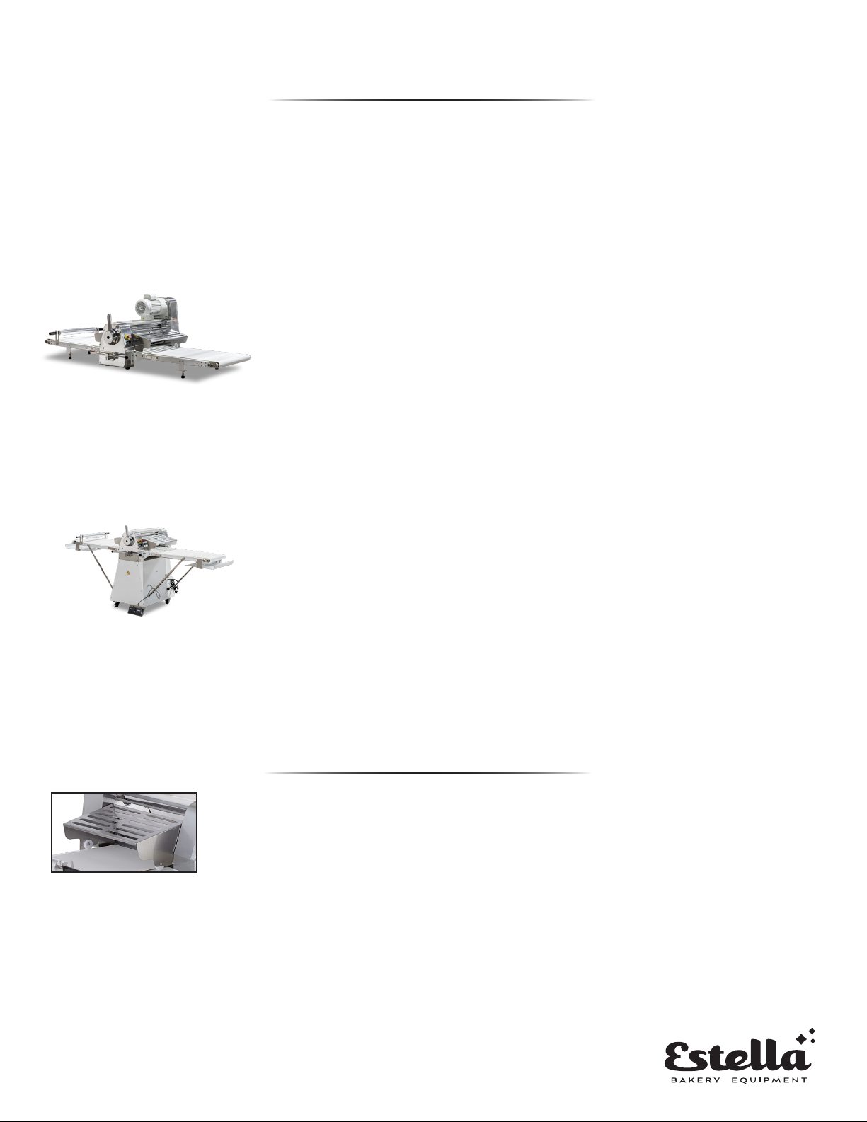
DOUGH SHEETERS
COUNTERTOP MODELS
FLOOR MODELS
USER MANUAL

Important Safety Information .....................................2
Setup...............................................................3
Safety Features ....................................................3
Operation .......................................................4-5
Circuit Diagram ....................................................6
Maintenance.......................................................6
Parts Diagrams.................................................7-16
Part Numbers ....................................................17
Troubleshooting .................................................17
Limited Warranty ................................................18
INDEX
1.

When using electrical appliances, basic safety precautions should always be followed,
including the following:
1. Keep the working around surrounding the machine clean and organized.
2. Consider environmental conditions surrounding the machine. Do not use the machine in humid,
wet or poorly lit environments. Do not use the machine close to flammable liquids or gas.
3. Keep machine away from children and non-authorized personnel. Do not permit them to go near
the machine or its working area.
4. Do not touch the switch or cable with wet hands.
5. Only utilize the machine with the correct voltage to achieve optimum results.
6. Do not wear low-hanging clothing or items that may get caught in the machine. Wear non-slip
shoes while working with the machine. For hygiene and safety, keep hair tied back and wear
protective gloves.
7. Do not tug on the cable to remove the plug from the outlet. Do not leave the cable near sharp
objects, water or solvents.
8. Remove the plug when the machine is not in use, you are cleaning the machine or need to move
the machine.
9. Check that the machine is not damaged prior to each use. Carefully check that all safety devices
are working, that the removable parts are not blocked, there are no parts damaged, that all the
parts have been set up correctly and that all conditions that could influence the regular function
of the machine are in working order.
10. If the machine is damaged or there are issues during its use, turn off the machine immediately
and contact the manufacturer for assistance or repair. Repairs should only be made by qualified
technicians, using the correct manufacturer parts. Non-compliance with these rules may void
the warranty.
NOTE: Save these instructions for future reference.
SAFETY
2.
1. The surface where the machine will be used must be solid and
horizontally level.
2. The machine is very heavy. Check weight capacity of the table or
counter it is being used on before installing.
3. These models have 4 adjustable feet. Once you have placed the
machine on the counter, use a level on each side of the belt to ensure
level operation.
4. Ensure the machine is close enough to a 120V outlet. Contact a
qualified electrician if unsure of your electrical supply.
The potentially most dangerous area of these machines is the two superimposed
cylinders with convergent rotation movements. So, there are safety bars that
obstruct the entry in this area. Those safety bars are completely built in stainless
steel and designed in a way to allow the user to watch the dough.
The machine can only begin its work if the security bars are in working position, that is, completely
down. The machine has an electric protection system that does not allow the machine to work if the
bars are not completely down.
It is forbidden to remove, modify or damage the security bars of the machine.
1. These models sit on 4 casters with brakes.
2. Ensure that the installation location is close enough to a 120V outlet.
Contact a qualified electrician if unsure of your electrical supply.
3. Keep the machine away from potential hazards like fryers, grills, or any
other piece of equipment that can splash hot oil or water onto it.
4. Unfold the belts down for use and sure enough working clearance. Use a
level on the belts to ensure that the machine is on a level surface.
COUNTERTOP MODELS
FLOOR MODELS
SETUP
NOTE: The manufacturer is not responsible for any damages caused by improper installation.
NOTE: The machine should be ran with a batch of test dough first that will not be used for consumption.
This is necessary to remove any lubricants that are on the rollers/belts from the new machine.
SAFETY FEATURES
3.
4.
1. Ensure the machine is plugged
in to a 120V outlet and the
working space is clear of any
potential hazards.
2. Locate the on off switch. Turn
on the power switch. (Before
start the switch, you need to
check whether the emergency
stop switch is turned on and safety
nets are all put down.
3. The thickness adjustment handle
can now be adjusted to your
desired dough thickness. Swing
the handle to the corresponding
scale to adjust the pressure roller
spacing.
4. Once that is set, prepare the belt
with flour as needed to prevent
sticking and add your dough to the belt. It is
recommended to start on the highest thickness
setting and work your way down. If you try to
force a large piece of dough into a small setting,
the rollers will not accept it.
5. Use the directional control to work the dough
through the rollers as many times as needed. Tabletop Model(s): Swing the left and right
levers to change the direction of the conveyor belt. Floor model(s) Use foot pedals to change
the direction of the conveyor beltKeep hands away from rollers and keep the safety guards
down. The machine will shut off immediately if safety guard is lifted.
6. Once done, return the direction control lever parallel to the floor and shut the machine off.
7. If Cleaning the machine, turn the power off and unplug it.
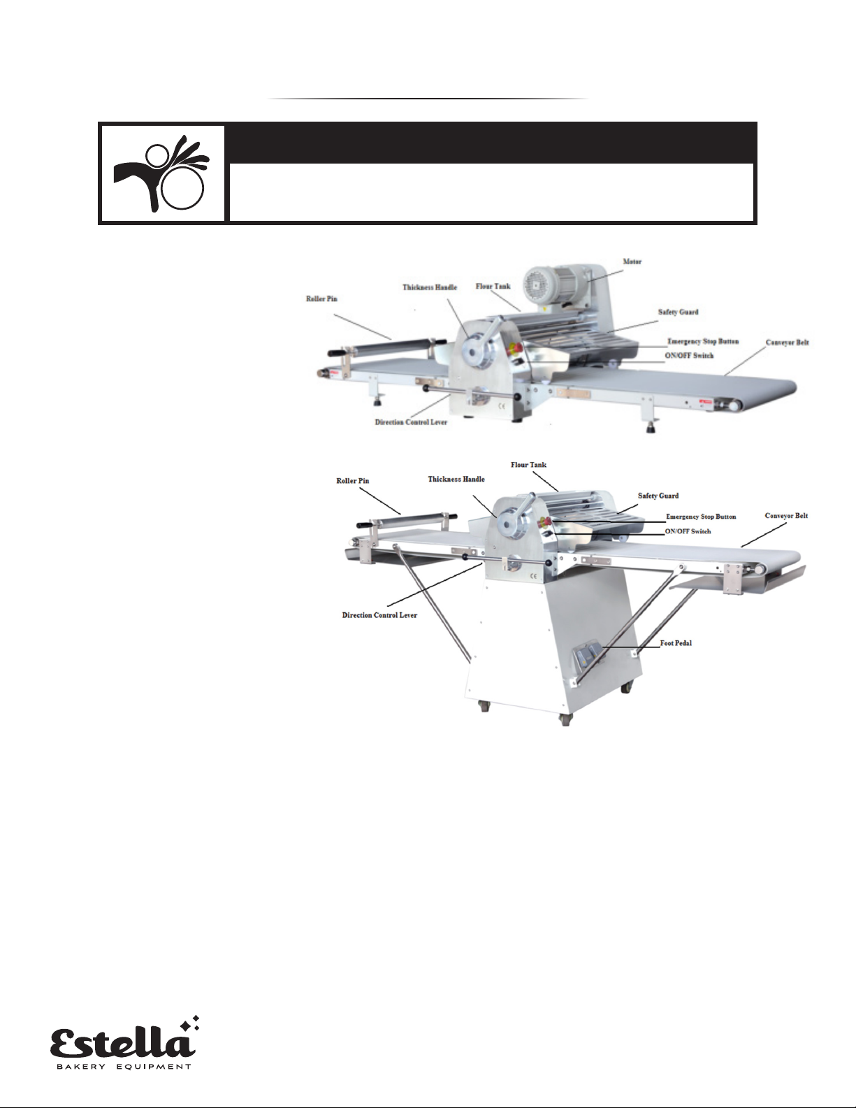
OPERATION
WARNING: MOVING PARTS CAN CRUSH & CUT
Keep hands, feet and all objects away from the rollers
prior to turning on the machine!

Swing the handle to the corresponding
scale to adjust the roller spacing of the
pressing surface.
Swing the left and right levers to change
the belt conveying direction.
Don't open this cover.
When the safety net is opened, the
machine will be stopped immediately,
and when it is put down, the machine
will continue to work.
TT-D18A
Dough Sheeter
Emergency stop
switch
Power switch
Operating Steps:
1. Turn on the power switch. (Before start the switch, you need to check whether the emergency stop switch is turned on and safety nets are
all put down)
2. Swing the handle to the corresponding scale to adjust the pressure roller spacing.
3. Swing the left and right levers to change the direction of the conveyor belt.
4. When the machine is running, if the safety protection net is opened, the machine will stop immediately. And then when the net is put down,
the machine will continue to work.
5. If meeting the emergency, please press the emergency stop immediately.
6. When the operation is completed, swinging the left and right levers to the horizontal, and then turning off the power switch.
Swing the handle to the corresponding
scale to adjust the roller spacing of the
pressing surface.
Swing the left and right levers to change
the belt conveying direction.
Stepping on the foot switch to jog the
conveyor belt (turn left and right)
Power switch
Emergency stop switch
When the safety net is opened, the machine
will be stopped immediately, and when it is
put down, the machine will continue to work.
Don't open this cover.
TT-D19A-1
Dough Sheeter
Operating Steps:
1. Turn on the power switch. (Before start the switch, you need to check whether the emergency stop switch is turned on and safety nets are all
put down)
2. Swing the handle to the corresponding scale to adjust the pressure roller spacing.
3. Swing the left and right levers to change the direction of the conveyor belt.
4. When the machine is running, if the safety protection net is opened, the machine will stop immediately. And then when the net is put down, the
machine will continue to work.
5. If meeting the emergency, please press the emergency stop immediately.
6. When the operation is completed, swinging the left and right levers to the horizontal, and then turning off the power switch.
Estella sheeters are designed to be used by qualified people in the pastry and bakery’s business. Other
uses will be considered improper. The manufacturer is not responsible for any machine damages or
personal injuries due to improper use of the machine
IMPROPER USE OF THIS MACHINE
Don't open this cover.
Power Switch
Emergency Power Switch
Swing the left and right levers to
change the belt conveying direction.
Swing the handle to the
corresponding scale to adjust the
roller spacing of the pressing surface.
When the safety net is opened, the
machine will stop immediately. When it
is put down, the machine will resume.
Swing the handle to the
corresponding scale to adjust the
roller spacing of the pressing surface.
Swing the left and right levers to
change the belt conveying direction.
Don't open this cover.
When the safety net is opened, the
machine will stop immediately. When it
is put down, the machine will resume.
Power switch
Emergency stop switch
Stepping on the foot switch to jog
the conveyor belt (turn left and right)
5.
• Before performing any sort of maintenance on the machine, first remove the
plug from the outlet.
• The machine must be cleaned every day that it is in use, especially areas that
contact dough.
• DO NOT use knives, hard brushes, or tools to clean the cylinders. use plastic tools
and/or soft sponges. Use a soft brush to clean the canvas.
• DO NOT use toxic products or abrasive agents as they could damage the machine.
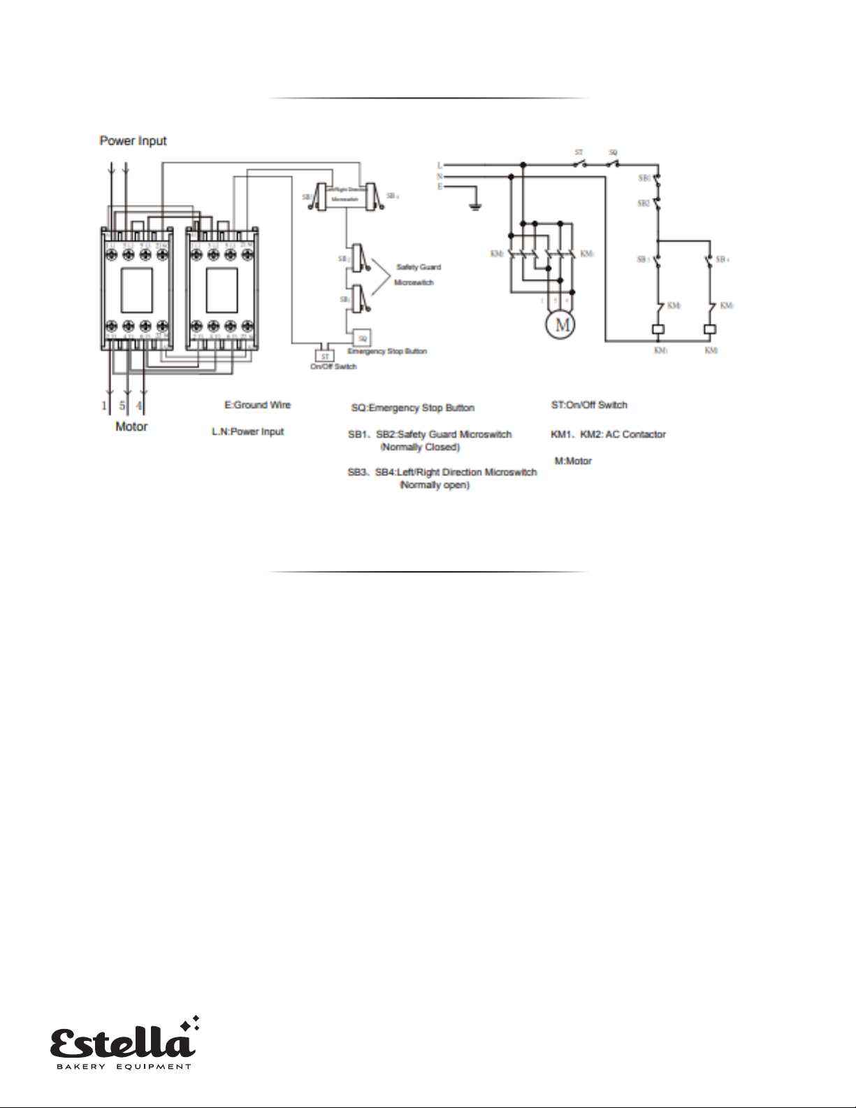
CIRCUIT DIAGRAM
MAINTENANCE
1. Using a proper brush and a wooden palate, first clean any flour residue and dough
off the machine.
2. To open the machine for cleaning, first lift the safety guards and adjust the roller
thickness to the largest setting.
3. You now have access to clean the rollers.
4. Rinse thoroughly and dry with an absorbent wipe. Wipe down all of the surfaces that
come into contact with the dough and then clean the entire machine with a smooth
cloth and a foodservice-safe disinfectant such as Nobles 147QUIKSAN.
5. Dry thoroughly before next use.
6.
7.
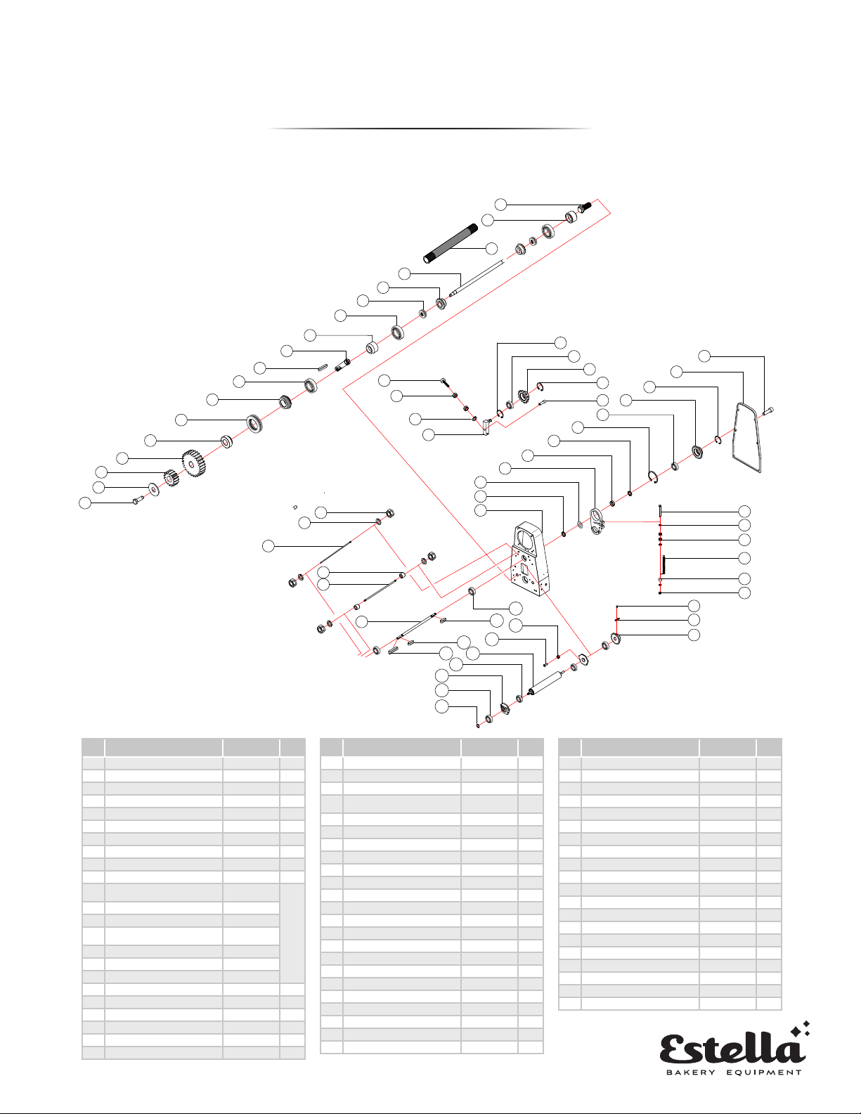
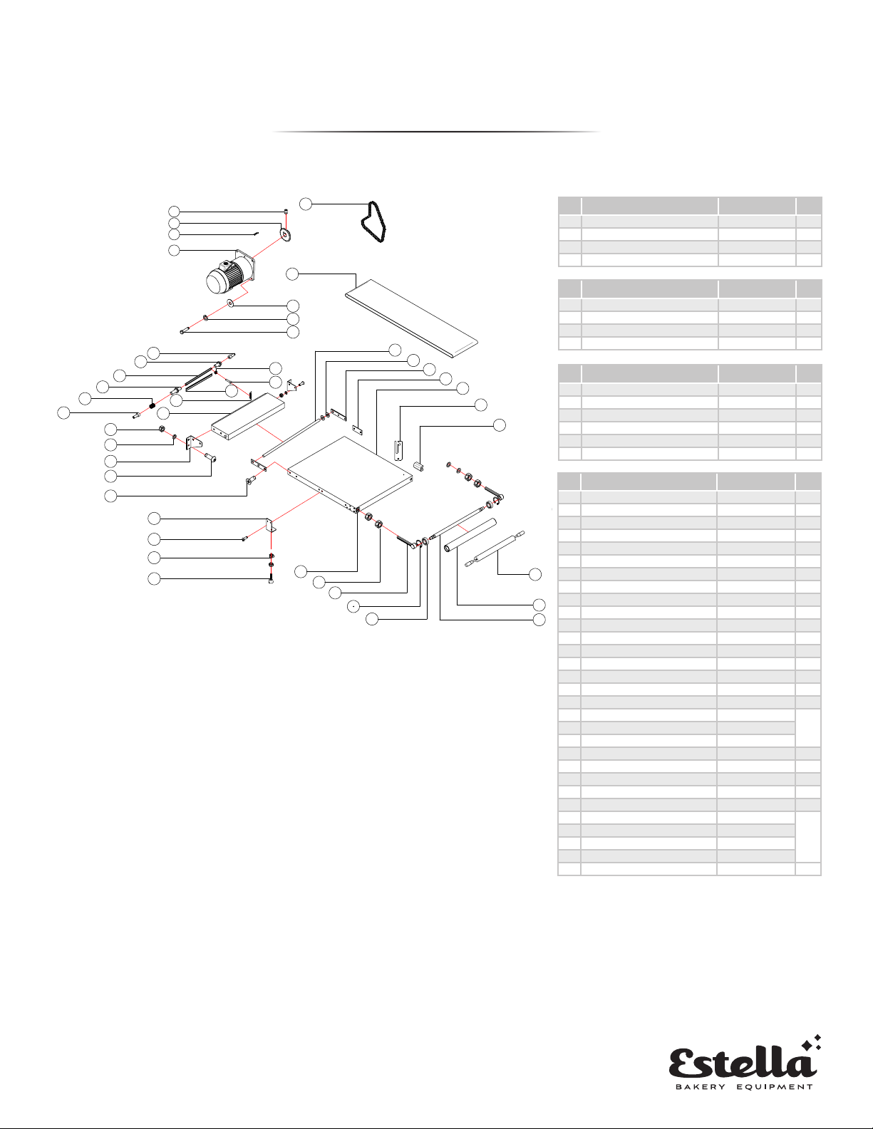
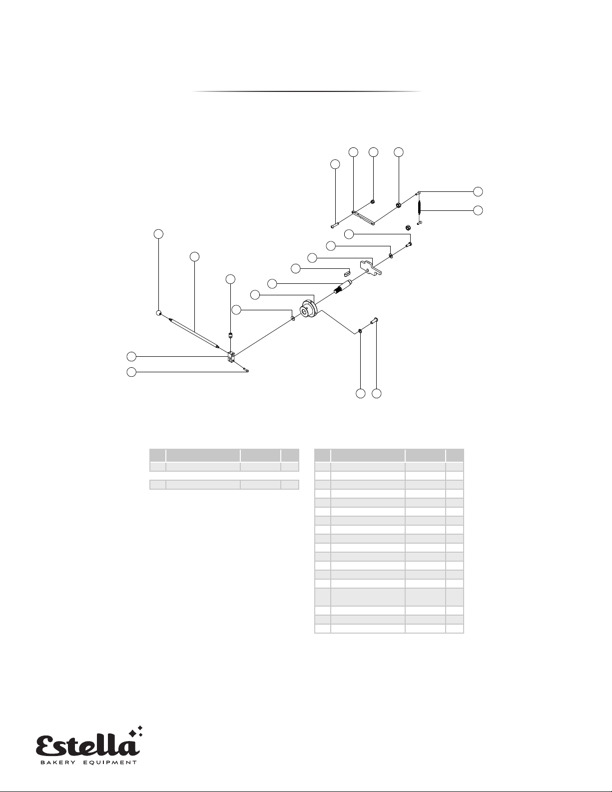
COUNTERTOP MODEL
PARTS DIAGRAMS
No Description Code
Qty
1 Hexagon screw M8x20L 1
28 at pad 1
3 Gear 15T TT520290 1
4 Gear 27T TT520280 1
5 Gasket TT520300 1
6 51108 Thrust Bearing 1
7 Bearing sleeve TT520320 1
8 6004 bearing 1
9C type 5x5x30L at key 1
10 Axis TT520310 1
11 Conveyor wheel bearing
sleeve TT520410
1 Set
12 6003 bearing
13 51103 Thrust Bearing
14 Aluminum blocks on both
sides of the roller
15 Roller shaft
16 Belt roller TT520420
17 Bearing sleeve TT520470
18 Adjusting bolt M20x50*2 1
19 Plastic head screw M10x78x30 1
20 M10 nut 1
21 10 spring pad 1
22 Fixed shaft TT450920 1
23 35 hole circlip 1
1
10
100
2
3
4
5
6
7
8
9
11
12
13
14
15
17
18
16
32
28
29
30
31
33
34
35
37
36
38
39
40
41
42
43
44
45
91
92
93
94
95
96
97
98
99
104
101
105
106
107
108
102
103
109
110
19
20
21
22
23
24
25
26
27
:
:
:
:
:
:
SECTION NAME
DRW No.
Designer
Check
Review
Scale
Date
LEFT ROLLER
ASSEMLY
AND
TOP ROLLER
ASSEMBLY
-- --
-- --
-- --
-- --
-- --
-- --
-- --
-- --
-- --
-- --
-- --
-- --
--
--
--
--
--
--
--
--
--
--
--
--
--
--
--
--
--
--
--
--
--
--
--
--
--
DESCRIPTION
VERSION DESRIPTION DATE
1st Drawing 2019/05/19A
B
C
D
E
F
DES IGNER
PRODUCT NAME
TABLE TOP
DOUGH SHEETER
TT-D18A
TT-D18B
LEFT ROLLER ASSEMBLY
AND TOP ROLLER
ASSEMBLY
LEFT ROLLER ASSEMBLY AND TOP ROLLER ASSEMBLY
No Description Code
Qty
24 6202 bearing 1
25 Sprocket TT520930 1
26 15 axis circlip 1
27 Hexagon socket head cap
screws M10x40L 1
28 Socket head bolt M6x20L 1
29 Cover TT450040 1
30 25 circlip 1
31 Sprocket 21T TT520500 1
32 6205 bearing 1
33 52 hole circlip 1
34 Washer 3mm 1
35 Eccentric block TT520210 1
36 Wheel adjustment block TT520101 1
37 Flat pad 3mm 1
38 Washer 6mm TT520770 1
39 Arm TT450020 1
40 M10 nut 1
41 10 spring pad 1
42 10x596 dental rod 1
43 Rubber sleeve TT520720 1
44 Fixed rod TT520710 1
45 Axis TT520450 1
46 Arm TT520010 1
No Description Code
Qty
91 Hex bolts M8x80L 1
92 8 spring pad 1
93 M8 nut 1
94 Tension spring 1.6x16x64 1
95 8 spring pad 1
96 M8 hat 1
97 Set screw M8x12L 1
98 C type 6x6x25 at key 1
99 Upper roller sprocket TT520510 1
100 6205 bearing 1
101 A type 6x6x18 at key 1
102 A type 6x6x18 at key 1
103 C type 6x6x30 at key 1
104 M5 nut 1
105 Hexagon pan head screws M5x20L 1
106 Roller (top) TT520440 1
107 6205 bearing 1
108 Wheel adjustment block TT520110 1
109 6205 bearing 1
110 20 axis circlip 1

8.
STARTER LEVER AND THICKNESS ASSEMBLY
46
47
48
49
50
51
52
53
54
55
56
59
60
57
58
61
62
63
64
65
66
67
68
69
70
71
72
73
74
75
76
77
78
79
80
81
82
83
84
85
86
111
112
113
114
115
116
118
119
117
:
:
:
:
:
:
SECTION NAME
DRW No.
Designer
Check
Review
Scale
Date
-- --
-- --
-- --
-- --
-- --
-- --
-- --
-- --
-- --
-- --
-- --
-- --
--
--
--
--
--
--
--
--
--
--
--
--
--
--
--
--
--
--
--
--
--
--
--
--
--
DESCRIPTION
VERSION DESRIPTION DATE
1st Drawing 2019/05/19A
B
C
D
E
F
DES IGNER
PRODUCT NAME
TABLE TOP
DOUGH SHEETER
TT-D18A
TT-D18B
START LEVER
AND THICKNESS
ASSEMBLY
START LEVER AND
THICKNESS ASSEMBLY
No Description Code
Qty
46 Arm TT520010 1
47 Washer 6mm TT520770 1
48 Flat pad 3mm 1
49 Wheel adjustment block TT520100 1
50 Eccentric block TT520210 1
51 Flat pad 3mm 1
52 Set screw M8x12L 1
53 Brake gear TT521870 1
54 Washer 3mm TT520770-1 1
55 6005 bearing 1
56 Brake bearing xing seat TT521820 1
57 Rotary shaft of brake TT521860 1
58 Brake xing seat TT521830 1
59 ¢ 10 spring pad 1
60 Hex bolts M10x30L 1
61 Brake cylinder TT521890 1
62 Socket head bolt M6x15L 1
63 M6 nut 1
64 Socket head bolt M6x20L 1
65 5x30 cotter pin 1
66 Socket head bolt M5x15L 1
67 5 spring pad 1
68 Brake gear TT521880 1
69 washer 22x¢32x3mm 1
70 6005 bearing 1
No Description Code
Qty
71 C type 6xx6x30 at key 1
72 A type 6x6x12 at key 1
73 A type 6x6x35 at key 1
74 Spring 0.9x9x14 1
75 Brake TT521840 1
76 24 axis circlip 1
77 Cover TT520030 1
78 A type 6x6x18 at key 1
79 Brake rotating disc TT521850 1
80 Fixed dial TT521910 1
81 Sealing ring TT521920 1
82 handle TT520050 1
83 Headless screw M10x35L 1
84 ¢ 10 at pad 1
85 M10 hat 1
86 HP-25 button plug 1
No Description Code
Qty
111 M12 nut 1
112 12 spring pad 1
113 12 Flat pad 1
114 Big foot pad TT450950 1
115 8 spring pad 1
116 M8 nut 1
117 Socket head bolt M6x16L 1
118 Socket head bolt M8x30L 1
119 Tension spring 1.6x16x76.8 1
COUNTERTOP MODEL
PARTS DIAGRAMS
9.
87
88
89
90
158
159
160
161
167
168
169
170
171
172
185
186
187
188
189
190
191
192
193
194
195
196
197
198
199
200
201
202
203
204
205
206
207
208
209
210
211
214
213
212
-- --
-- --
-- --
-- --
-- --
-- --
-- --
-- --
-- --
-- --
-- --
-- --
:
:
:
:
:
:
--
--
--
--
--
--
--
--
--
--
--
--
--
--
--
--
--
--
--
--
--
--
--
--
--
DESCRIPTION
VERSION DESRIPTION DATE
1st Drawing 2019/05/19A
B
C
D
E
F
DES IGNER
PRODUCT NAME
SECTI ON NAME
DRW No.
Designer
Check
Review
Scale
Date
TABLE TOP
DOUGH SHEETER
TT-D18A
TT-D18B
TRANSMISSION
AND
CONVEYOR
ASSEMBLY
TRANSMISSION
AND
CONVEYOR
ASSEMBLY
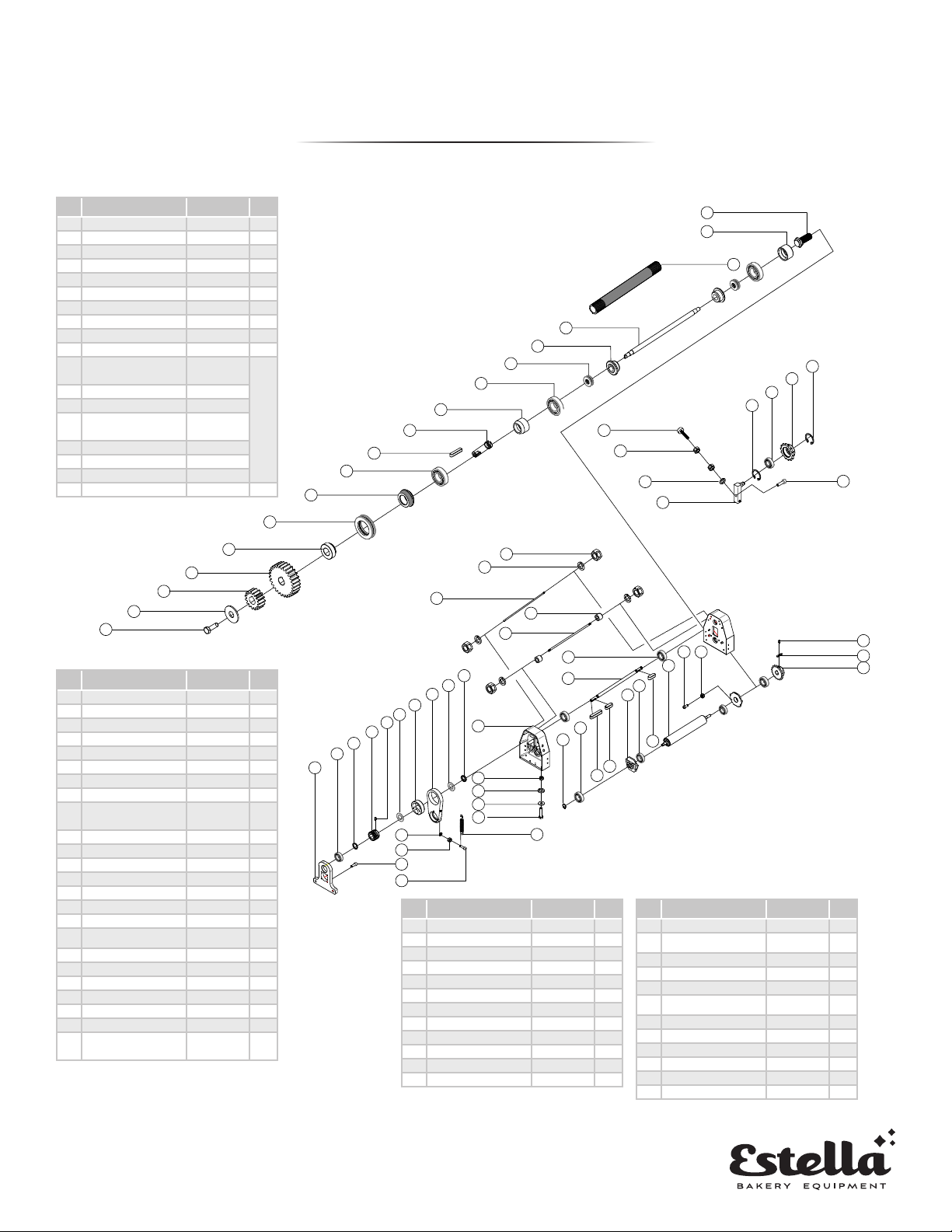
TRANSMISSION AND CONVEYOR ASSEMBLY
No Description Code
Qty
87 Set screw M8x12L 1
88 Sprocket 24T TT520520 1
89 C type 7x8x30 at key 1
90 Motor GV28-550-17S 1
No Description Code
Qty
158 10 at pad 1
159 10 spring pad 1
160 Hex bolts M10x35L 1
161 08A 50HZ / 08A 60HZ 88/86 1
No Description Code
Qty
167 Hexagon socket head cap screws M10x16L 1
168 Positioning pin TT52066-1 1
169 Lower knife cover TT520680 1
170 Positioning pin TT52066-3 1
171 Compression spring 1.0x10.4x22 1
172 Hexagon socket head cap screws M10x16L 1
No Description Code
Qty
185 Bracket foot pad TT450970 1
186 M8 nut 1
187 Hexagon pan head screws M6x10L 1
188 Tripod TT450960 1
189 Cross countersunk head screws M10x25L 1
190 Hexagon pan head screws M10x25L 1
191 Fixed plate (left and right) TT520530 1
192 10 spring pad 1
193 M10 nut 1
194 Pallet TT520540 1
195 Tension spring 1.5x10x80 1
196 Lower blade TT520690 1
197 M6 nut 1
198 Phillips pan head screws M6x10L 1
199 Fixed rod TT520550-1 1
200 Gasket 16x30x1.5 1
201 Connector TT520560 1
202 Support plate reinforced plate TT520570-4
1 Set203 Bracket plate TT520570
204 Bracket plate xing seat TT520570-2
205 Rolling pin xing seat TT520790 1
206 conveyor 2160x500 1
207 16 at pad 1
208 M16 nut 1
209 Rolling surface xing rod TT520580 1
210 20 axis circlip
1 Set
211 6004 bearing
212 Roller lever TT520610
213 Conveyor belt roller TT520600
214 Rolling pin 1
COUNTERTOP MODEL
PARTS DIAGRAMS

10.
120
121
122
123
124
125
126
127
128
129
130
131
132
133
134
135
136
137
145
146
:
:
:
:
:
:
SECTION NAME
DRW No.
Designer
Check
Review
Scale
Date
-- --
-- --
-- --
-- --
-- --
-- --
-- --
-- --
-- --
-- --
-- --
-- --
--
--
--
--
--
--
--
--
--
--
--
--
--
--
--
--
--
--
--
--
--
--
--
--
--
DESCRIPTION
VERSION DESRIPTION DATE
1st Drawing 2019/05/19A
B
C
D
E
F
DES IGNER
PRODUCT NAME
TABLE TOP
DOUGH SHEETER
TT-D18A
TT-D18B
DIRECTION
HANDLE
ASSEMBLY
DIRECTION HANDLE
ASSEMBLY
DIRECTION HANDLE ASSEMBLY
No Description Code
Qty
120 M5 nut 1
121 M8 hat 1
122 Cam strip TT520150 1
123 Hexagon pan head screws M8x35L 1
124 M6x6 set screw 1
125 Adjustment lever TT520370 1
126 plastic ball TT520320 1
127 Left and right adjustment seat TT520360 1
128 Socket head bolt M8x30L 1
129 Hexagon pan head screws M8x20L 1
130 8 spring pad 1
131 16 large at pads 1
132 Fixed seat TT520070 1
133 axis TT520140 1
134 A type 6x6x12 at key 1
135 Adjustment lm TT520080 1
136 8 at pad 1
137 Hex bolts M8x20L 1
No Description Code
Qty
145 Tension spring 1.4x11x88 1
146 Socket head bolt M5x20L 1
138
139
140
141
142
143
144
147
148
149
150
151
152
153
154
155
156
157
162
163
164
165
166
174
173
175
176
177
178
179
180
181
182
183
184
:
:
:
:
:
:
SECTI ON NAME
DRW No.
Designer
Check
Review
Scale
Date
BOTTOM
ROLLER
ASSEMBLY
-- --
-- --
-- --
-- --
-- --
-- --
-- --
-- --
-- --
-- --
-- --
-- --
--
--
--
--
--
--
--
--
--
--
--
--
--
--
--
--
--
--
--
--
--
--
--
--
--
DESCRIPTION
VERSION DESRIPTION DATE
1st Drawing 2019/05/19A
B
C
D
E
F
DES IGNER
PRODUCT NAME
TABLE TOP
DOUGH SHEETER
TT-D18A
TT-D18B
No Description Code
Qty
138 Hex bolts M10x20L 1
139 10 at pad 1
140 52 hole circlip 1
141 6005 bearing 1
142 Adjustment block TT520090 1
143 M10 nut 1
144 10 spring pad 1
No Description Code
Qty
147 Plastic gear shaft (top) TT520230 1
148 Gear M3 15T TT520250 1
149 13 Retaining ring 1
150 Upper blade TT520670 1
151 Positioning pin TT52066-2 1
152 Upper knife cover TT520660 1
153 6 spring pad 1
154 M6 nut 1
155 Cross pan head bolt M6x30L 1
156 Tension spring 1.6x12x43 1
157 Roller (below) TT520430 1
BOTTOM ROLLER ASSEMBLY
No Description Code
Qty
162 6206 bearing 1
163 Set screw M8x12L 1
164 Sprocket 1
165 C type 6x6x25 at key 1
166 A type 6x6x35 at key 1
No Description Code
Qty
173 Gear M3 24T TT520270 1
174 Washer 6mm TT520770 1
175 Gear M3 10T TT520260 1
176 Plastic gear shaft (below) TT520240 1
177 Plastic head screw M8x37L 1
178 M8 nut 1
179 8 spring pad 1
180 Micro switch sleeve TT520760 1
181 10 at pad 1
182 Protection net TT520740 1
183 Protection net rubber wheel TT520750 1
184 Hexagon socket head cap
screws M6x15L 1
COUNTERTOP MODEL
PARTS DIAGRAMS
11.
FLOOR MODEL
PARTS DIAGRAMS
LEFT ROLLER ASSEMBLY AND TOP ROLLER ASSEMBLY
No Description Code
Qty
1 Hexagon screw M8x20L 1
28 at pad 1
3 Gear 15T TT520290 1
4 Gear 27T TT520280 1
5 Gasket TT520300 1
6 51108 Thrust Bearing 1
7 Bearing sleeve TT520320 1
8 6004 bearing 1
9C type 5x5x30L at key 1
10 axis TT520310 1
11 Conveyor wheel
bearing sleeve TT520410
1 Set
12 6003 bearing
13 51103 Thrust Bearing
14 Aluminum blocks on
both sides of the roller
15 Roller shaft
16 Belt roller TT520420
17 Bearing sleeve TT520470
18 Adjusting bolt M20x50*2 1
28
29
1
2
3
4
5
6
7
8
9
10
11
12
13
14
15
16
18
30
31
32
42
41
40
39
38
37
36
35
34
33
17
74
76
75
73
77
81
80
79
78
82
83
84 112113
114
116
117
120
121
119
118
115
105
104
103
19
20
21
23
24
25
26
22
27
:
:
:
:
:
:
SECTION NAME
DRW No.
Designer
Check
Review
Scale
Date
-- --
-- --
-- --
-- --
-- --
-- --
-- --
-- --
-- --
-- --
-- --
-- --
--
--
--
--
--
--
--
--
--
--
--
--
--
--
--
--
--
--
--
--
--
--
--
--
--
DESCRIPTION
VERSION DESRIPTION DATE
1st Drawing 2019/05/19A
B
C
D
E
F
DES IGNER
PRODUCT NAME
LEFT ROLLER
ASSEMBLY
AND
TOP ROLLER
ASSEMBLY
FLOOR TYPE
DOUGH SHEETER
TT-D19A-1
TT-D19B-1
LEFT ROLLER ASSEMBLY
AND
TOP ROLLER
ASSEMBLY
No Description Code
Qty
19 Plastic head screw M10x78x30 1
20 M10 nut 1
21 10 spring pad 1
22 Fixed shaft TT450920 1
23 35 hole circlip 1
24 6202 bearing 1
25 Sprocket TT520930 1
26 15 axis circlip 1
27 Hexagon socket head
cap screws M10x40L 1
28 M10 nut 1
29 10 spring pad 1
30 10x596 dental rod 1
31 Rubber sleeve TT520720 1
32 Fixed rod TT520710 1
33 Washer 6mm TT520770 1
34 Flat pad 3mm 1
35 Wheel adjustment
block TT520100 1
36 Eccentric block TT520210 1
37 Flat pad 3mm 1
38 Set screw M8x12L 1
39 Brake gear TT520870 1
40 Washer 3mm TT520770-1 1
41 6005 bearing 1
42 Brake bearing xing
seat TT521820 1
No Description Code
Qty
73 Socket head bolt M8x30L 1
74 Socket head bolt M6x16L 1
75 M8 nut 1
76 8 spring pad 1
77 Tension spring 1.6x16x76.8 1
78 Hex bolts M12x50L 1
79 12 Flat pad 1
80 12 spring pad 1
81 M12 nut 1
82 Arm TT520010 1
83 Axis TT520450 1
84 6205 bearing 1
No Description Code
Qty
112 M5 nut
113 Hexagon pan head
screws
114 Roller (top)
115 A type 6x6x18 at key
116 6205 bearing
117 Wheel adjustment
block
118 A type 6x6x18 at key
119 C type 6x6x30 at key
120 6205 bearing
121 ¢ 20 axis circlip
109 6205 bearing 1
110 20 axis circlip 1
12.
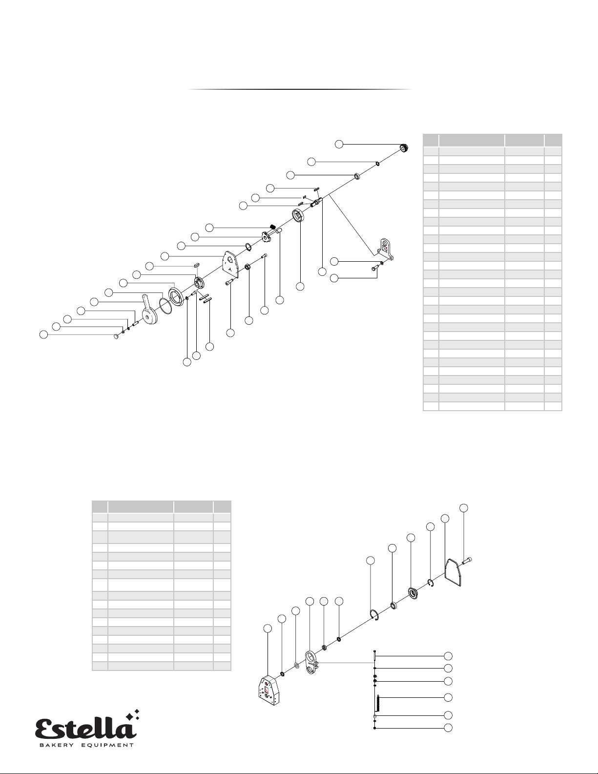
STARTER LEVER AND THICKNESS ASSEMBLY
FLOOR MODEL
PARTS DIAGRAMS
44
43
45
46
47
48
70
49
50
68
69
51
52
53
55
56
57
58
59
60
61
54
67
66
65
64
63
62
71
72
:
:
:
:
:
:
SECTION NAME
DRW No.
Designer
Check
Review
Scale
Date
-- --
-- --
-- --
-- --
-- --
-- --
-- --
-- --
-- --
-- --
-- --
-- --
--
--
--
--
--
--
--
--
--
--
--
--
--
--
--
--
--
--
--
--
--
--
--
--
--
DESCRIPTION
VERSION DESRIPTION DATE
1st Drawing 2019/05/19A
B
C
D
E
F
DES IGNER
PRODUCT NAME
START LEVER
AND THICKNESS
ASSEMBLY
FLOOR TYPE
DOUGH SHEETER
TT-D19A-1
TT-D19B-1
START LEVER
AND THICKNESS
ASSEMBLY
No Description Code
Qty
43 Brake gear TT521880 1
44 washer 22x32x3mm 1
45 6005 bearing 1
46 C type 6xx6x30 at key 1
47 A type 6x6x12 at key 1
48 A type 6x6x35 at key 1
49 spring 0.9x9x14 1
50 brake TT521840 1
51 24 axis circlip 1
52 Cover TT520030 1
53 A type 6x6x18 at key 1
54 Brake rotating disc TT521850 1
55 Fixed dial TT521910 1
56 Sealing ring TT521920 1
57 handle TT520050 1
58 Headless screw M10x35L 1
59 10 at pad 1
60 M10 hat 1
61 HP-25 button plug 1
62 5 spring pad 1
63 Socket head bolt M5x15L 1
64 5x30 cotter pin 1
65 Socket head bolt M6x20L 1
66 M6 nut 1
67 Socket head bolt M6x15L 1
68 Brake cylinder TT521890 1
69 Brake xing seat TT521830 1
70 Rotary shaft of brake TT520101 1
71 Hex bolts M10x30L 1
72 10 spring pad 1
RIGHT ROLLER ASSEMBLY
No Description Code
Qty
85 Washer 6mm TT520770 1
86 Flat pad 3mm 1
87 Wheel adjustment
block TT520101 1
88 Eccentric block TT520210 1
89 Washer 6mm 520770 1
90 52 hole circlip 1
91 6205 bearing 1
92 Adjusting shaft
sprocket M3 21T TT520500 1
93 25 axis circlip 1
94 Cover TT520040 1
95 Socket head bolt M6x20L 1
96 Hex bolts M8x80L 1
97 8 spring pad
98 M8 nut
99 Tension spring 1.6x16x64
100 8 spring pad
101 M8 hat
85
86
87 88 89
90
91
92
93
94
95
96
97
98
99
101
100
238
:
:
:
:
:
:
SECTION NAME
DRW No.
Designer
Check
Review
Scale
Date
-- --
-- --
-- --
-- --
-- --
-- --
-- --
-- --
-- --
-- --
-- --
-- --
--
--
--
--
--
--
--
--
--
--
--
--
--
--
--
--
--
--
--
--
--
--
--
--
--
DESCRIPTION
VERSION DESRIPTION DATE
1st Drawing 2019/05/19A
B
C
D
E
F
DES IGNER
PRODUCT NAME
RIGHT ROLLER
ASSEMBLY
FLOOR TYPE
DOUGH SHEETER
TT-D19A-1
TT-D19B-1
RIGHT ROLLER
ASSEMBLY
13.
FLOOR MODEL
PARTS DIAGRAMS
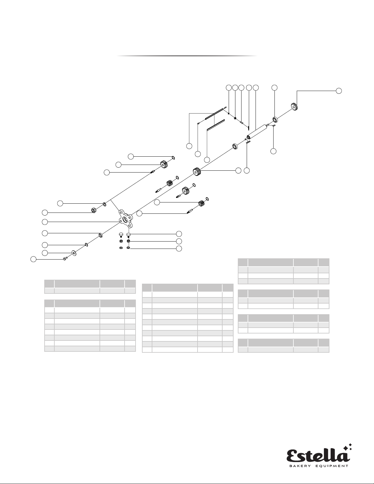
BOTTOM ROLLER ASSEMBLY
122
111 110 109 108 107 106
102
123
124
125
126
127
128
129
130
132
134
135
136
162
161
160
177
174173
167
166
:
:
:
:
:
:
SECTION NAME
DRW No.
Designer
Check
Review
Scale
Date
-- --
-- --
-- --
-- --
-- --
-- --
-- --
-- --
-- --
-- --
-- --
-- --
--
--
--
--
--
--
--
--
--
--
--
--
--
--
--
--
--
--
--
--
--
--
--
--
--
DESCRIPTION
VERSION DESRIPTION DATE
1st Drawing 2019/05/19A
B
C
D
E
F
DESIGNER
PRODUCT NAME
BOTTOM
ROLLER
ASSEMBLY
FLOOR TYPE
DOUGH SHEETER
TT-D19A-1
TT-D19B-1
BOTTOM
ROLLER
ASSEMBLY
No Description Code
Qty
102 Sprocket (double row) TT521490 1
No Description Code
Qty
106 6206 bearing 1
107 Roller (below) TT520430 1
108 Tension spring 1.6x12x43 1
109 Cross pan head bolt M6x30L 1
110 M6 nut 1
111 6 spring pad 1
122 Upper knife cover TT520680 1
123 Positioning pin TT52066-2 1
No Description Code
Qty
160 8 spring pad 1
161 M8 nut 1
162 Plastic head screw M8x37L 1
No Description Code
Qty
166 Plastic gear shaft (below) TT520240 1
167 Gear M3 10T TT520260 1
No Description Code
Qty
173 Gear M3 24T TT520270 1
174 A type 6x6x35 at key 1
No Description Code
Qty
177 C type 6x6x25 at key 1
No Description Code
Qty
124 Upper blade TT520670 1
125 13 Retaining ring 1
126 Gear M3 15T TT520250 1
127 Plastic gear shaft (top) TT520230 1
128 10 spring pad 1
129 M10 nut 1
130 Adjustment block TT520090 1
132 6005 bearing 1
134 52 hole circlip 1
135 10 at pad 1
136 Hex bolts M10x20L 1
14.
DIRECTION HANDLE ASSEMBLY
FLOOR MODEL
PARTS DIAGRAMS
131
133
137139 138
140
141
142
143
144
145
146
148
149
150
151
152
154153
147
:
:
:
:
:
:
SECTION NAME
DRW No.
Designer
Check
Review
Scale
Date
-- --
-- --
-- --
-- --
-- --
-- --
-- --
-- --
-- --
-- --
-- --
-- --
--
--
--
--
--
--
--
--
--
--
--
--
--
--
--
--
--
--
--
--
--
--
--
--
--
DESCRIPTION
VERSION DESRIPTION DATE
1st Drawing 2019/05/19A
B
C
D
E
F
DESIGNER
PRODUCT NAME
DIRECTION
HANDLE
ASSEMBLY
FLOOR TYPE
DOUGH SHEETER
TT-D19A-1
TT-D19B-1
DIRECTION HANDLE
ASSEMBLY
No Description Code
Qty
131 Socket head bolt M5x20L 1
133 Tension spring 1.4x11x88 1
No Description Code
Qty
137 M5 nut 1
138 M8 hat 1
139 Cam strip TT520150 1
140 Hexagon pan head screws M8x35L 1
141 Hex bolts M8x20L 1
142 8 at pad 1
143 Adjustment lm TT520080 1
144 A type 6x6x12 at key 1
145 axis TT520140 1
146 Fixed seat TT520070 1
147 16 large at pads 1
148 M6x6 set screw 1
149 Adjustment lever TT520370 1
150 plastic ball TT520320 1
151 Left and right adjustment
seat TT520360 1
152 Socket head bolt M8x30L 1
153 ¢ 8 spring pad 1
154 Hexagon pan head screws M8x20L 1

15.
FLOOR MODEL
PARTS DIAGRAMS
UPPER BODY MACHINE ASSEMBLY
158
157
155
156
159
163
164
165
214
215
216
217
210
211
212
213
204
205
206
207
208
209
218
:
:
:
:
:
:
SECTION NAME
DRW No.
Designer
Check
Review
Scale
Date
-- --
-- --
-- --
-- --
-- --
-- --
-- --
-- --
-- --
-- --
-- --
-- --
--
--
--
--
--
--
--
--
--
--
--
--
--
--
--
--
--
--
--
--
--
--
--
--
--
DESCRIPTION
VERSION DESRIPTION DATE
1st Drawing 2019/05/19A
B
C
D
E
F
DESIGNER
PRODUCT NAME
UPPER
MACHINE
BODY
ASSEMBLY
FLOOR TYPE
DOUGH SHEETER
TT-D19A-1
TT-D19B-1
UPPER MACHINE
BODY ASSEMBLY
No Description Code
Qty
155 Cover TT520130 1
156 Phillips pan head screws M6x10L 1
157 Base plate TT520120 1
158 Noodle stick xing seat (left and right) TT520120-7 1
159 Motor (380V) GH28-550-17S 1
No Description Code
Qty
163 C type 7x8x30 at key 1
164 Sprocket 24T TT520520 1
165 Set screw M8x12L 1
No Description Code
Qty
204 M12 nut 1
205 ¢ 12 spring pad 1
206 ¢ 12 Flat pad 1
207 Hexagon Screw M12x40L 1
208 Motor mount TT520120-4 1
209 Fixed frame (reinforcement) TT520120-5 1
210 Brake caster 1
211 ¢ 8 at pad 1
212 ¢ 8 spring pad 1
213 Hex bolts M8x35L 1
214 M8 hat 1
215 Support frame TT520120-1 1
216 Phillips pan head screws M6x15L 1
217 Hex bolts M8x60L 1
218 Bottom plate TT520120-3 1

16.
CONVEYOR ASSEMBLY
FLOOR MODEL
PARTS DIAGRAMS
183
182
181
180
176
175 187
188
179
178
172
171
170
169
168
202
201
200
199
198
203
226
224
223
222
221
220
219
230
231
232
233 234 235 236 237
197 196 195 194 193 192
189
229
228
225
227
239 240
241
186
185
191
190
184
:
:
:
:
:
:
SECTION NAME
DRW No.
Designer
Check
Review
Scale
Date
-- --
-- --
-- --
-- --
-- --
-- --
-- --
-- --
-- --
-- --
-- --
-- --
--
--
--
--
--
--
--
--
--
--
--
--
--
--
--
--
--
--
--
--
--
--
--
--
--
DESCRIPTION
VERSION DESRIPTION DATE
1st Drawing 2019/05/19A
B
C
D
E
F
DES IGNER
PRODUCT NAME
CONVEYOR
ASSEMBLY
FLOOR TYPE
DOUGH SHEETER
TT-D19A-1
TT-D19B-1
CONVEYOR
ASSEMBLY
No Description Code
Qty
168 Cross countersunk
head screws M10x25L 1
169 Hexagon pan head
screws M10x25L 1
170 Fixed plate (left and
right) TT520530 1
171 10 spring pad 1
172 M10 nut 1
No Description Code
Qty
175 Hexagon socket
head cap screws M10x16L 1
176 Compression spring 1.0x10.4x22 1
No Description Code
Qty
178 Pallet TT520540 1
179 Tension spring 1.5x10x80 1
180 Positioning pin TT52066-3 1
181 Lower knife cover TT520680 1
182 Positioning pin TT52066-1 1
183 Hexagon socket
head cap screws M10x16L 1
184 Protection net TT520740 1
185 Protection net
rubber wheel TT520750 1
186 Hexagon socket
head cap screws M6x15L 1
187 M6 nut 1
188 Phillips pan head
screws M6x10L 1
189 Lower blade TT520690 1
190 Micro switch sleeve TT520760 1
191 10 at pad 1
192 conveyor 2160x500 1
193 Bracket plate xing
seat TT520570-2
1 Set
194 Bracket plate TT520570
195 Support plate
reinforced plate TT520570-4
196 Connector TT520560 1
197 Fixed rod TT520550-1 1
198 M10 hat 1
199 10 at pad 1
200 Upper movable pole
seat 1
201 Hexagon pan head
screws M10x40L 1
202 Movable rod TT520640 1
203 Fixed rod TT520630 1
No Description Code
Qty
219 Sheng material plate aluminum pad 1
220 Sheng block xed block (left and right) TT520580-1 1
221 Hexagon pan head screws M8x10L 1
222 M8 hat 1
223 Hexagon pan head screws M8x10L 1
224 08A 50HZ / 08A 60HZ 70/68 1
225 Powder tank TT520730 1
226 08A 62 1
227 Powder shield TT520810 1
228 Panel rubber wheel 1
229 Hexagon socket head cap screws M6x30L 1
230 Sheng material board TT520620 1
No Description Code
Qty
231 16 at pad 1
232 M16 nut 1
233 Rolling surface xing rod TT520580 1
234 20 axis circlip
1 Set
235 6004 bearing
236 Roller lever TT520610
237 Conveyor belt roller TT520600
239 Gasket TT520790 1
241 Rolling pin 1
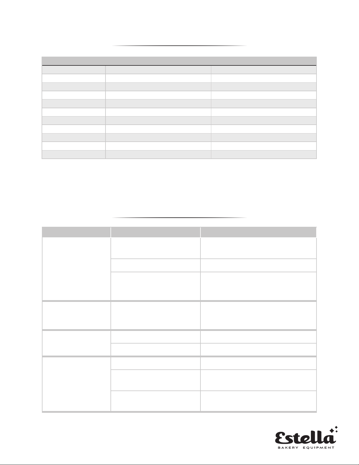
TROUBLESHOOTING
Issue Cause Solution
The machine won’t start
The machine is not plugged in or
connected to a source of power
Check the general switch, the plug, and the
feeding cable
The voltage input is incorrect Use the proper voltage
There is another issue with the
machine
Stop using the machine immediately and
contact the manufacturer for assistance
The machine causes an
electric shock
Wires are touching the structure
of the machine
Check the wires, conrming that they are
not touching the structure of the machine
Only one set of rollers
is working
The belt is broken Change the belt
The worm wheel is worn out Change the worm wheel
The machine is making a
loud noise
Lubrication needed Check all lubrication points and add
Loose chain Check that the transmission chain is
connected. Replace if damaged
Worn out bearings Check machine bearings for any wear/tear.
Replace if damaged
7.
ITEM # COMPATIBLE ITEM # PART DIAGRAM #
348PDS67UBLD 348DSC67 Countertop Model #150
348PDS78UBLD 348DSC78 & 348DSF78 Countertop Model #150 & Floor Model #124
348PDS94UBLD 348DSF94 Floor Model #124
348PDS67LBLD 348DSC67 Countertop Model #196
348PDS78LBLD 348DSC78 & 348DSF78 Countertop Model #196 & Floor Model #189
348PDS94LBLD 348DSF94 Floor Model #189
348PDS67TANK 348DSC67 Countertop Model #215
348PDS78TANK 348DSC78 & 348DSF78 Countertop Model #215 & Floor Model #225
348PDS94TANK 348DSF94 Floor Model #225
348PDSUSPRNG 348DSC67, 348DSC78, 348DSF78, 348DSF94 Countertop Model #156 & Floor Model #108
348PDSLSPRNG 348DSC67, 348DSC78, 348DSF78, 348DSF94 Countertop Model #195 & Floor Model #179
PART NUMBERS
Other manuals for 348DSC67
2
This manual suits for next models
3
Table of contents
Other Estella Commercial Food Equipment manuals


Popular Commercial Food Equipment manuals by other brands


Igloo
Igloo SANTIAGO BEMAR Series user manual

Bartscher
Bartscher 900 SERIES Installation, use and maintenance

Studio 54
Studio 54 DAIQUIRI ECO Instructions for use

Structural Concepts
Structural Concepts GHSS476HRD.5718 user manual

Angelo Po
Angelo Po 191BR1G Use and installation manual

Hendi
Hendi THERMOSYSTEM user manual